Lecture Strength of Materials I: Chapter 6 - PhD. Tran Minh Tu
Bạn đang xem bản rút gọn của tài liệu. Xem và tải ngay bản đầy đủ của tài liệu tại đây (3.6 MB, 28 trang )
STRENGTH OF MATERIALS
1/10/2013
TRAN MINH TU - University of Civil Engineering,
Giai Phong Str. 55, Hai Ba Trung Dist. Hanoi, Vietnam
1
CHAPTER
6
TORSION
1/10/2013
Contents
6.1. Introduction
6.2. Torsional Loads on Circular Shafts
6.3. Strength Condition and stiffness condition
6.4. Statically Indeterminate Problem
6.5. Strain Energy
6.6. Examples
Home’s works
1/10/2013
3
6.1. Introduction
1/10/2013
4
6.1. Introduction
1/10/2013
5
6.1. Introduction
Torsion members – the slender members subjected to torsional
loading, that is loaded by couple that produce twisting of the member
about its axis
Examples – A torsional moment (torque) is applied to the lug-wrench
shaft, the shaft transmits the torque to the generator, the drive shaft of
an automobile...
• Torsional Loads on Circular Shafts: the torsional moment or couple
A
F
B
x
C
Q1
z
y
1/10/2013
Q2
T
1
t
1
T
2
t
2
6
6.1. Introduction
Internal torsional moment diagram
• Using method of section
• Sign convention of Mz
- Positive: clockwise
- Negative: counterclockwise
M
z
0
Mz > 0
Mz =
y
y
z
z
x
1/10/2013
x
7
6.2. Torsion of Circular Shafts
6.2.1. Simplifying assumptions
1/10/2013
8
6.2. Torsion of Circular Shafts
=> In the cross-section, only shear stress exists
6.2.2. Compatibility
• Consider the portion of the shaft
shown in the figure
• CD – before deformation
• CD’ – after deformation
- From the geometry
DD ' d dz
=> The Shear strain:
d
dz
- d – the angle of twist
- Following Hooke’s law:
1/10/2013
G G
d
dz
9
6.2. Torsion of Circular Shafts
6.2.3. Equilibrium
d 2
d
M z dA G
dA G
Ip
dz A
dz
A
d M z
– the rate of twist
dz GI p
6.2.3. Torsion formulas
– Shearing stress
Mz – internal torsional moment
Mz
Ip
1/10/2013
Ip – polar moment of inertia
– radial position
10
6.2. Torsion of Circular Shafts
- Maximum shearing stress
max
Mz
Mz
R
Ip
Wp
- Wp - Section modulus of torsion
– Angle of twist
c
a
b
O
A
B
L
From 6.2.3:
1/10/2013
A
L
M z dz
M dz
z
GI p
GI p
B
0
AB
rad
11
6.2. Torsion of Circular Shafts
Mz
const
GI p
– Multiply torques
AB
M zL
GI p
GIp – stiffness of torsional shaft
If the shaft is subjected to several different torques or cross-sectional
area, or shear modulus changes abruptly from one region of the shaft to
the next.
Mz
const
GI p i
AB
1/10/2013
Mz
li
i 1 GI p
i
n
12
6.2. Torsion of Circular Shafts
1/10/2013
13
6.3. Strength Condition – Stiffness condition
Strength condition:
0
max
Mz
Wp
- Determine experimentally 0
n
- Third strength hypothesis 3
- Fourth strength hypothesis 4
2
3
Stiffness condition:
max
1/10/2013
Mz
GI
p max
rad / m
14
6.3. Strength Condition – Stiffness condition
Three main problems:
For a circular shaft:
max
Mz
Mz
max
3
4
0.2D
0.1GD
1. Investigating the strength condition, (stiffness condition)
max
Mz
???
3
0.2D
2. Determine the diameter of circular cross-section
Mz
D 3
0.2
3. Determine the maximum torque
1/10/2013
M z 0.2 D3
15
6.4. Statically Indeterminate Problem
AD = 0
AD AB BD
1/10/2013
AB
z
AB
p
BD
z
BD
p
M a M 2a
GI
GI
32
MA M
33
MD
M
B
a
d
A
(2)
MD M a
M D 2a
AD
4
4
G 0,1 2d G 0,1 d
1
MD M;
33
MA
2d
• Assume that the reactions at the fixed
ends MA, MD are shown in the figure.
• Equilibrium: MA + MD = M
(1)
• Compatibility condition:
D
2a
CD
M
M
BD
z
AB
z
MD
MD M
Mz
MD
D
z
M/33
0
Mz
32M/33
16
6.5. Strain Energy
• For a shaft subjected to a torsional
load,
2
2 2
U
xy
2G
dV
T
2GJ
2
dV
• Setting dV = dA dx,
T 2 2
U
dA dx
dA dx
2
2
2GJ
2GJ A
0A
0
L
xy
T
J
T 2 2
L
L
T2
dx
2GJ
0
• In the case of a uniform shaft,
T 2L
U
2GJ
1/10/2013
17
6.6. Example Problem 1
1/10/2013
3M
M
B
C
2a
D
A Circular shaft made from two
segments, each having diameter
of D and 2D. The Shaft is
subjected to the torques shown
in the figure.
1. Draw the internal torsional
moment diagram
2. Determine
the
maximum
shearing stress
3. Determine the angle of twist of
the end D with respect to B
With
M=5kNm;
a=1m;
D=10cm; G=8.103 kN/cm2
2D
•
D
a
18
6.6. Example Problem 1
M
CD
z
B
2a
M
D
a
3M
3M 15kNm
MzCD
Segment BC 0 z2 2a
BC
z
C
D
1. Internal
2D
torsional moment
diagram
Segment CD 0 z1 a
3M
M
z1
M
3M
2M 10kNm
MzBC
z2
a
15
10
1/10/2013
Mz
kNm
19
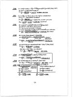
6.6. Example Problem 1
3M
M
max
CD
max
BC
M zBC
0, 2 2 D
3
B
C
2a
10 102
0,625(kN / cm2 )
3
0, 2 20
10
max 7,5(kN / cm2 )
D
M zCD
15 102
7,5(kN / cm2 )
3
3
0,2 D
0,2 10
2D
2. Maximum shearing stress
D
a
15
Mz
kNm
3. Angle of twist of end D
D BC CD
M zCD a M zBC 2a
D
CD
GI p
GI pBC
15 102 102
10 102 2 102
D
0,02(rad )
3
4
3
4
8 10 0,110 8 10 0,1 20
1/10/2013
20
6.6. Example Problem 2
1/10/2013
21
6.6. Example Problem 2
1/10/2013
22
6.6. Example Problem 2
1/10/2013
23
Homework
1/10/2013
24
Homework
1/10/2013
25