FEM analysis of high-selectivity SAW filter using SPUDT structure
Bạn đang xem bản rút gọn của tài liệu. Xem và tải ngay bản đầy đủ của tài liệu tại đây (587.18 KB, 5 trang )
Journal of Science and Technology 123 (2017) 014-018
FEM Analysis of High-Selectivity SAW Filter using SPUDT Structure
2
Tran Manh Ha1,2, Do Quang Huy1, Hoang Si Hong1, Nguyen Thi Hue1*
Hanoi University of Science and Technology, No. 1, Dai Co Viet, Hai Ba Trung, Hanoi, Viet Nam
The Vietnam Research Institute of Electronics, Informatics and Automation, 156A Q.Thanh Str, Hanoi, Vietnam
Received: August 30, 2017; Accepted: November 03, 2017
1
Abstract
Wide-band surface acoustic wave (SAW) filters using single-phase unidirectional interdigital transducer
(SPUDT) showed promise to achieve low loss and high selectivity. In this paper, the SAW filters were studied
via finite element method (FEM) using 2D models and utilized YZ-LiNbO3 for piezoelectric substrate. With
respect to the investigated center frequencies of 97 MHz and 179 MHz, the SPUDT SAW filter demonstrated
low power losses (26.85 dB and 22.63 dB respectively) and high attenuation band (12.73 dB and 23.95 dB)
in comparison to the bidirectional SAW filter. It was also identified that the changes in different electrode
factors including the material, the thickness, and the quantity had influences on the SPUDT-type filter
response.
Keywords: SAW filter, SPUDT, FEM
1. Introduction
*
properties [1, 2, 9]. The common disadvantage of these
methods is that they require the parameters that could
be only determined from experimental process or
numerical determination [10]. Among existing
simulation methodologies, finite element method
(FEA) is considered as the most accurate technique for
SAW devices analysis without fabrication [5].
Elsherbini and Ionescu used FEM to simulate SAW
one-port resonators and focused their applications on
sensing systems [5, 11].
Typical SAW filters based on bidirectional
transducer structure (Bi-IDT) are affected by internal
reflection among interdigital transducers (IDTs) [1, 2],
which depends on the thickness and materials of
electrodes [3], not only causing multiple-transit signal
leading to power loss and passband ripples, but also
deteriorating the passband shape and high-order
resonant modes [2].
Non-symmetric transducer
configuration, such as single-phase unidirectional
transducers (SPUDTs), could be used in SAW filter
design in order to prevent both load-dependent
reflection and electrode reflectivity caused by
connecting reflective transducer with finite-impedance
load [2]. Therefore, this type of SAW filter achieves
low insertion loss, high selectivity and almost no
passband ripple [3, 4, 5]. Thus, this research utilizes
this transducer geometry for designing low-loss, highselectivity SAW filter.
Accordingly, in this paper the frequency
responses of SAW filter using SPUDT structures are
analyzed in comparison to the responses of
bidirectional IDT-based filter via FEM. After that, the
influences of different transducer parameters (i.e. the
material, the thickness, and the quantity) on the
performance of the SAW filter would be examined.
The piezoelectric substrate material is YZ-LiNbO3.
The center frequencies are chosen as 97 MHz and 179
MHz to satisfy the requirements of high frequency
filters in practice.
To analyse SPUDTs, Hua Jiang et al. expressed
the electro acoustic characteristics of IDTs via Pmatrix model [6]. Also, Pyman et al. developed
withdrawal weighting and apodization algorithms
based on delta function model to analyze W-CDMA
base station filters using SPUDT structures [7]. In
addition, the stopband width and directionality
dependence of SPUDTs could be evaluated using
spectral theory [8]. Other studies used coupling-ofmodes (COM) modeling to analyze transducer
2. Principles of SAW filter with SPUDT structure
The core purpose of the SPUDT structure is to
obtain acceptable suppression of the multiple-transit
signal by eliminating the reflection of the forward
acoustic port under the circumstances of wellmatching impedance of the electrical port.
Consequently, it could be designed to reach low
insertion loss and low reflectivity [2, 12].
Corresponding author: Tel.: (+84) 986320168
Email: ;
*
14
Journal of Science and Technology 123 (2017) 014-018
thickness and width are 1 mm and 30 mm to reduce the
computational cost. The piezoelectric material for
substrate is YZ-LiNbO3 because of its high
electromechanical coupling factor (4.82%) compared
with those factors of ST-Quartz (0.16%),
ZnO/sapphire (1.1%), or XY-LiNbO3 (3.58%),
resulting in wideband response that is more applicable
for filter realization [14, 16, 17]. The properties of YZLiNbO3 used in simulation was demonstrated in Ref.
27 [18]. The chosen material for fingers is aluminum
and the finger thickness is 2.5%.
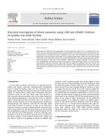
Fig. 1. Distributed acoustic reflection transducer.
The most common method to arrange IDTs for
achiving the unidirectionality is using distributed
acoustic reflection transducer (DART) [2]. Fig. 1
shows the particular arrangement of IDTs in the
DART. Each wavelength (λ0) period, with respect to
one electrode group, contains three fingers: two with
the width of λ0/8 and one with the width of λ0/4. To
define the distance between the fingers, the transducers
are considered as reflection center (RC) and
transduction center (TC). The reflection center is the
point at which waves incident both forward and
backward have equal reflection coefficient, and the
transduction center refers to the point where the
forward and backward waves are in-phase and have
same amplitude. The backward is reflected and then
emerged with the forward. The condition for the
reinforcement at the center frequency is [2]:
𝑑𝑑 = (2𝑛𝑛 ± 1)𝜆𝜆0 /8
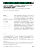
(a)
(b)
(1)
Fig. 2. 2D models of SAW filters using: (a) SPUDT
and (b) Bi-IDT.
Thus, the effective distance between the transduction
and reflection centers is 3λ0/8 [2, 5, 9, 13].
3.2 Influences of transducer parameters on the
response of SPUDT-based SAW filter
3. Simulation methodology
This section describes two main simulation work
in this research: 1) the comparison of SAW filter
responses between the cases of SPUDT and Bi-IDT,
and 2) the influences of different transducer
parameters on the response of SPUDT-based SAW
filter.
The second approach was to investigate the
frequency responses of SAW filter using SPUDT with
respect to the changes of the material, the thickness,
and the number of electrodes.
Since different materials could obtain different
levels of mechanical surface wave reflection [3], the
first parameter that need to be considered is electrode
material properties. Although most of SAW devices
commonly use aluminum for electrodes, the drawback
of this material is its small density leading to overthick film pattern for fabrication [3]. To handle this
obstacle, large-mass density materials with good
electrical conductivity could be used to fabricate IDTs
[19]. From this point of view, Cu and Au should be
good alternatives for Al. The properties of Al, Cu, and
Au used in simulation are listed in Table 1. The center
frequency f0 is 179MHz, the relative thickness (h/λ0) is
0.025, and the number of input IDT groups are 8.
3.1 Comparison of SPUDT and Bi-IDT SAW filter
responses
The initial approach is to utilize FEM analysis in
order to compare the responses of SAW filter based on
two transducer structures: SPUDT and Bi-IDT. Fig. 2a
demonstrates the 2D model of the SPUDT filter, which
is designed to be consistent with the DART
mechanism introduced above. In the context of Bi-IDT
structure, an optimal model for the Bi-IDT structure
was proposed by Tran et al. [14]. Accordingly, similar
Bi-IDT model and simulation tool would be applied to
in this paper. The cross section of the Bi-IDT
configuration is shown in Fig. 2b.
The SAW wavelengths (λ0) could be calculated
from 𝑓𝑓0 = 𝑣𝑣0 ⁄𝝀𝝀0 [15]. In both cases, the substrate
After that, the effect of aluminum transducer
thickness on SPUDT-based filter response is studied,
in which the number of input electrode groups are kept
at 8 with the center frequency of 179 MHz, and the
15
Journal of Science and Technology 123 (2017) 014-018
relative electrode thickness varies from 0.025 to 0.075
with a step of 0.025.
In all circumstances, the reduction of phase
velocity caused by IDT mass loading effect results in
frequency-shifting events compared with theoretical
calculations [20]. However, because the number of
SPUDTs are greater than the number of Bi-IDTs in
order to adjust the filter bandwidths, it is observable
that the center frequencies of SPUDT-based filters are
somewhat smaller than the center frequencies of BiIDT-based filters.
Table 1. Properties of electrode materials [3]
Al
Cu
Au
Mass density (x103 kg/m3)
2.697
8.93
19.32
Young’s modulus (GPa)
70.3
129.8
78.0
Poisson ratio
0.345 0.343 0.440
4.2 Influences of transducer parameters on the
response of SPUDT-based SAW filter
Resistivity (x10-8 Ωm)
3.55 2.23 2.88
Lastly, the performance of SAW devices in
respect of the number of electrode groups are
investigated in both cases of 97 MHz and 179 MHz
wavelengths. Aluminum electrodes with the relative
thickness of 0.025 are utilized.
4. Results and discussion
4.1 Comparison of SPUDT and Bi-IDT SAW filter
responses
The responses of SAW filters using SPUDT and
Bi-IDT structures are presented in Fig. 3. As shown in
Fig. 3a with f0 = 97 MHz, compared to the Bi-IDT
filter, the SPUDT model has lower insertion loss of
26.85dB, higher attenuation band of 12.73dB, and
steeper slope resulting in high-selectivity filter. In case
of 179 MHz resonant frequency, the SPUDT filter also
performs an attenuation band of 23.95dB, which is
much higher than the attenuation band of Bi-IDT filter
that is only 14.43dB as in Fig. 3b. The insertion loss
and filter slope of the SPUDT filter also significantly
improve.
Fig. 4. Comparision of SPUDT SAW filter responses
with different electrode materials.
(a)
Fig. 5. Comparision of SPUDT SAW filter responses
with different electrode thicknesses.
The SPUDT SAW filter responses with respect to
different electrode materials are shown in Fig. 4. As
can be seen in the figure, the filter using aluminum
electrodes demonstrates the most significant response,
particularly the lowest insertion loss (22.63 dB),
highest attenuation band (23.95 dB), and steepest
slope, as well as frequency correctness (6.3 MHz). The
utilizations of cooper and gold deteriorate the filter
response because Cu and Au have much greater mass
densities than Al, but smaller stiffness coefficients,
consequently leading to larger mechanical reflections
and effective velocity reductions [3, 19].
(b)
Fig. 3. Filter responses of SPUDT and Bi-IDT SAW
filters: (a) f0 = 97 MHz and (b) f0 = 179 MHz.
16
Insertion loss
15.25
-32.3
4
Attenuation band
18
16
12.73
12.1
14
10.53
12.58 12
10
8
6
-32.75
-36.3
4
-26.85
-30.1
2
0
6
8
10
12
NUMBER OF IDT GROUPS
(b)
INSERTION LOSS (DB)
0
-5
-10
-15
-20
-25
-30
-35
-40
ATTENUATION BAND (DB)
INSERTION LOSS (DB)
(a)
-20
-21
Insertion loss
24.08
21.85
Attenuation band
-22.48 -22.54
-22
-23
-24
-25
-26
-22.63
-25.58
8
30
23.95
15.07
25
20
15
12.53 10
-24.74
10
12
14
16
NUMBER OF IDT GROUPS
5
0
ATTENUATION BAND (DB)
Journal of Science and Technology 123 (2017) 014-018
Fig. 6. Frequency responses of SAW filters with respect to different numbers of IDT groups in cases (a) f0 = 96.9
MHz and (b) f0 = 178.9 MHz.
Fig. 5 presents the simulation results when the
thickness of aluminum electrodes varies from 2.5% to
7.5% of a wavelength. It is crystal clear that the filter
responses become worse when the electrode thickness
increases. Particularly, the best case is when h/λ0
equals 0.025, in which the insertion loss is 26.85 dB,
and the attenuation band is 15.73 dB. In contrast, with
the relative thickness of 0.10, the insertion loss and
attenuation band deteriorate to 32.76 dB and 12.01 dB.
It is because the internal reflectivity in each transducer
would rise with respect to the increase of electrode
thickness [3]. Besides, the decrease of the center
frequencies when the electrodes become thicker could
be simply explained as the growth of the total mass
load of IDT, which leads to the reduction of the phase
velocity [20].
the quantity) are also investigated. Accordingly, the
simulation results firstly showed that the frequency
response of SAW filter depended on the mass density
and stiffness coefficient of electrode material;
therefore, using aluminum electrode resulted in the
greatest performance. Also, the deterioration of filter
response is directly proportional with the increase of
finger thickness. Finally, the SPUDT geometry was
simulated in respect of different numbers of
transducers, which revealed a trade-off amongst power
loss, rejection, selectivity, and bandwidth as well as
optimal numbers of electrodes to achieve acceptable
insertion loss and attenuation band for the center
frequencies of 97 MHz and 179 MHz. Further research
should utilize 3D model to investigate the effects of
IDT length on the filter response as well as other
advanced SPUDT geometries.
The relation between the loss and the attenuation
of the SPUDT SAW devices and the number of IDT
groups are presented in Fig. 6. It could be seen clearly
that the properties of SAW filter would vary when the
number of IDTs change. While the center frequency is
97 MHz (Fig. 6a), the filter achieves low insertion loss
and large attenuation band when the number of
electrode groups in input IDTs are 12, which might be
considered as the optimal number; in other cases, the
filter has to trade off amongst power loss and
attenuation rejection. Similarly, as seen in Fig. 6b, the
optimal geometry for 179 MHz device might contain 8
IDT groups in order to reduce power loss and obtain
reasonable selectivity.
Acknowledgments
This research is supported by University project
T2017-PC-100 of Hanoi University of Science and
Technology.
References
[1] C. S. Hartmann, P. V. Wricjht, R. J. Kansy and E. M.
Garber, An Analysis of SAW Interdigital Transducers
with Internal Reflections and The Application to The
Design of Single-Phase Unidirectional Transducers,
Ultrasonics Symposium (1982) 40-45.
[2] D. Morgan, Surface Acoustic Wave Filters With
Applications to Electronic Communications and
Signal Processing, Northampton: Elsevier, (2007).
4. Conclusion
In this research, we analyzed the frequency
responses of SAW filter based on SPUDT structure via
2D finite element analysis. In comparison to the BiIDT SAW filter, the SPUDT geometry gives better
responses, in both of insertion loss and attenuation
band, in order to achieve high-selectivity filters. The
relations between the device performance and different
electrode properties (i.e. the material, the thickness and
[3] S. Nakagomi, H. Asano, H. Tanaka, T. Omori, K.-y.
Hashimoto and M. Yamaguchi, Single-Phase
Unidirectional Surface Acoustic Wave Transducer
Using Cu Electrode, Japanese Journal of Applied
Physics 42 (2003) 3152-3156
17
Journal of Science and Technology 123 (2017) 014-018
[4] C. C. Ruppel, Acoustic Wave Filter Technology - A
Review, IEEE Transactions on Ultrasonics,
Ferroelectrics, and Frequency Control, (2016).
Distributed Acoustic Reflection Transducers, IEEE
Ultrasonic Symposium (1986) 59-64.
[14] H. M. Tran, P. H. Nguyen, L. K. Linh, D. V. Nguyen
, H. T. L. Nguyen, H. T. Nguyen and H. S. Hoang, 2D
Simulation of High Frequency Filter based on Surface
Acoustic Wave Principle using Quartz Piezoelectric
Substrate, in 3rd Vietnam Conference on Control and
Automation, Thai Nguyen (2015).
[5] V. Ionescu, Design and Analysis of A Rayleigh SAW
Resonator For Gas Detecting Applications,"
Romanian Journal of Physics 60 (2015) 502-511.
[6] H. Jiang, W. Lu, S. Shen and Z. Xie, Study of a low
insertion loss SAW filter with SPUDT structure using
YZ-LiNbO3, Applied Mechanics and Materials 251
(2013) 139-142.
[15] J. Kirschner, Surface Acoustic Wave Sensors
(SAWS):
Design
for
Application,
Microelectromechanical Systems (2010).
[7] A. C. Pyman, J. M. Deacon, W. Gibson, R. S. Bains,
J. D. Galipeau, T. M. Lindemayer and F. Z. Bi, "Using
SPUDT Structure to Design High Selectivity WCDMA Base Station Filters, IEEE Ultrasonics
Symposium, (2001) 279-282.
[16] M. Kadota, Y. Kuratani, T. Kimura, M. Esashi and S.
Tanaka, Ultra-Wideband and High Frequency
Resonators using Shear Horizontal Type Plate Wave
in LiNbO3 Thin Plate, Japanese Journal of Applied
Physics 53 (2014).
[8] E. J. Danicki, Spectral Theory of Single-Phase
Unidirectional Transducers, (2005).
[17] D. Ciplys and R. Rimeika, Measurements of
Electromechanical Coupling Coefficient for Surface
Acoustic Waves in Proton-Exchanged Lithium
Niobate, Applied Physics Letters (1998) 14-20.
[9] H. Oh, K. Lee, K. Eun, S.-H. Choa and S. S. Yang,
Development of a High-Sensitivity Strain
Measurement System based on a SH SAW Sensor,
Journal of Micromechanics and Microengineering
(2012).
[18] M. M. E. Gowini and W. A. Moussa, A Finite Element
Model of a MEMS-based Surface Acoustic Wave
Hydrogen Sensor, Sensors 10 (2010) 1232-1250.
[10] M. M. E. Gowini and W. A. Moussa, A Reduced Three
Dimensional Model for SAW Sensors Using Finite
Element Analysis, Sensors 9 (2009) 9945-9964.
[19] T. Omori, S. Nakagomi, H. Tanaka, H. Asano, K.-y.
Hashimoto and M. Yamaguchi, SAW Reflection
Characteristics of Cu Electrodes and their Application
to SAW IF Devices, IEEE Ultrasonics Symposium
(2002) 19-23.
[11] M. M. Elsherbini, M. F. Elkordy and A. M. Gomaa,
Finite Element Method Simulation for SAW
Resonator-Based Sensors, International Electrical
Engineering Journal 7 (2016) 2167-2172.
[20] A. K. Namdeo and H. B. Nemade, FEM Study on the
Effect of Metallic Interdigital Transducers on Surface
Acoustic Wave (SAW) Velocity in SAW Devices, in
The 2011 COMSOL Conference, Bangalore (2011).
[12] C. S. Hartmann and B. P. Abbott, Overview of Design
Challenges for Single Phase Unidirectional SAW
Filter, IEEE Ultrasonics Symposium (1989) 79-89.
[13] T. Kodama, H. Kawabata, Y. Yasuhara and H. Sato,
Design of Low-Loss SAW Filters Employing
18