Sơ đồ thủy lực máy đào CAT 320 - P3
Bạn đang xem bản rút gọn của tài liệu. Xem và tải ngay bản đầy đủ của tài liệu tại đây (202.37 KB, 7 trang )
Systems Operation
320C U Excavator Hydraulic System
Main Hydraulic System
SMCS - 5050; 5051; 5069; 5117; 5472
Main Hydraulic Schematic
Shutdown SIS
Previous Screen
Product: EXCAVATOR
Model: 320C EXCAVATOR MAC
Configuration: 320C U & 320C LU Excavators
MAC00001-UP (MACHINE) POWERED BY 3066 Engine
Media Number -RENR3845-01 Publication Date -01/12/2002 Date Updated -11/12/2002
i02164926
Page 1 of 7320C U & 320C LU Excavators MAC00001-UP (MACHINE) POWERED BY 3066 Engine(S
...
18/03/2002mhtml:file://C:\V-Trac\Phu tung,bao duong\Schematic\Hydraulic sys\Main Hydraulic System.
...
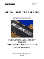
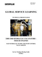
Illustration 1 g01098090
(1) Swing motor
(2) Left travel motor
(3) Right travel motor
(4) Stick cylinder
(5) Travel brake valve (left)
(6) Travel brake valve (right)
(7) Bucket cylinder
(8) Boom cylinder
(9) Swivel
(10) Pilot control valve (travel)
(11) Stick drift reduction valve
(12) Main control valve
(13) Boom drift reduction valve
(14) Pressure switch
(15) Pressure switch
(16) Pilot control valve (swing and stick)
(17) Pilot control valve (boom and bucket)
(18) Main relief valve
(19) Pressure switch
(20) Accumulator
(21) Reducing valve (boom priority mode or swing priority mode)
(22) Pressure sensor (left pump)
(23) Solenoid valve (swing parking brake)
(24) Hydraulic activation valve
(25) Solenoid valve (hydraulic activation)
Page 2 of 7320C U & 320C LU Excavators MAC00001-UP (MACHINE) POWERED BY 3066 Engine(S
...
18/03/2002mhtml:file://C:\V-Trac\Phu tung,bao duong\Schematic\Hydraulic sys\Main Hydraulic System.
...
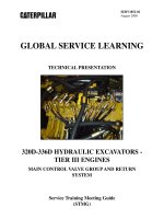
Hydraulic Pump Flow and Pressure Control System
(26) Left pump (view from shaft end)
(27) Travel speed solenoid valve
(28) Pilot oil manifold
(29) Drain filter
(30) Pilot relief valve
(31) Pilot filter
(32) Right pump (view from shaft end)
(33) Pilot pump
(34) Slow return check valve
(35) Bypass check valve
(36) Pressure sensor (right pump)
(37) Proportional reducing valve (power shift pressure)
(38) Oil cooler
(39) Return filter
(40) Hydraulic tank
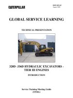
Illustration 2 g00748918
Pump compartment
(26) Left pump
Page 3 of 7320C U & 320C LU Excavators MAC00001-UP (MACHINE) POWERED BY 3066 Engine(S
...
18/03/2002mhtml:file://C:\V-Trac\Phu tung,bao duong\Schematic\Hydraulic sys\Main Hydraulic System.
...
This machine is driven and controlled by the following systems.
z
The main hydraulic system controls the cylinders, the travel motors and the swing motor.
z
The pilot hydraulic system supplies oil to the main pumps, the main control valve, the
swing brake and the travel motors.
z
The electronic control system controls the outputs of the engine and pump.
The main hydraulic system delivers oil flow from right pump (32) and left pump (26) in order
to control the following components: bucket cylinder (7), stick cylinder (4), boom cylinders
(8), right travel motor (3), left travel motor (2) and swing motor (1).
Right pump (32) and left pump (26) are variable displacement piston pumps. The performance
of both pumps is equal.
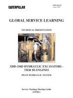
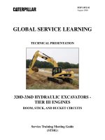
(32) Right pump
(33) Pilot pump
(37) Proportional reducing valve (power shift pressure)
(41) Delivery line (right pump)
(42) Delivery line (left pump)
Illustration 3 g00748919
Main control valve
(18) Main relief valve
(43) Right control valve body
(44) Left control valve body
Page 4 of 7320C U & 320C LU Excavators MAC00001-UP (MACHINE) POWERED BY 3066 Engine(S
...
18/03/2002mhtml:file://C:\V-Trac\Phu tung,bao duong\Schematic\Hydraulic sys\Main Hydraulic System.
...
Right pump (32) is directly connected to the engine by a flexible coupling. The right pump
delivers oil to the right control valve body (43) of the main control valve. Left pump (26) is
mechanically connected to the right pump through gears. The left pump delivers oil to the left
control valve body (44) of the main control valve. Gear type pilot pump (33) supplies oil to the
pilot hydraulic system. Gear type pilot pump (33) is directly connected to right pump (32) by a
coupling. All engine output is used to drive these three pumps.
As the load pressure increases during working conditions, the main pumps increase the
delivery pressure and the pumps decrease the flow rate. The hydraulic horsepower remains
constant even though the delivery pressure and the flow rates change. The hydraulic
horsepower is approximately identical to the engine horsepower.
When no work is being performed, pump oil flows through main control valve (12) and into
hydraulic tank (40). The main control valve sends a negative flow control signal to each main
pump regulator in order to destroke the pump to the minimum output flow.
If an operation is being performed, main control valve (12) directs pump oil to the respective
cylinders (boom, bucket, and stick) and/or motors (swing and travel). Main control valve (12)
contains numerous valve stems, passages, check valves, and orifices in order to carry out a
single operation or a combined operation. The working pressure of the main hydraulic system
is regulated by main relief valve (18).
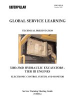
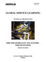
Illustration 4 g00680656
Cab
(45) Monitor panel
(46) Joystick (stick and swing)
(47) Joystick (boom and bucket)
(48) Left travel lever/pedal
(49) Right travel lever/pedal
Page 5 of 7320C U & 320C LU Excavators MAC00001-UP (MACHINE) POWERED BY 3066 Engine(S
...
18/03/2002mhtml:file://C:\V-Trac\Phu tung,bao duong\Schematic\Hydraulic sys\Main Hydraulic System.
...