Study of coexistence between indoor LTE femtocell and outdoor-to-indoor DVB-T2-Lite reception in a shared frequency band
Bạn đang xem bản rút gọn của tài liệu. Xem và tải ngay bản đầy đủ của tài liệu tại đây (1.87 MB, 15 trang )
Seediscussions,stats,andauthorprofilesforthispublicationat: />
StudyofcoexistencebetweenindoorLTE
femtocellandoutdoor-to-indoorDVB-T2-Lite
receptioninasharedfrequencyband
ARTICLEinEURASIPJOURNALONWIRELESSCOMMUNICATIONSANDNETWORKING·DECEMBER2015
ImpactFactor:0.72·DOI:10.1186/s13638-015-0338-x
CITATION
READS
1
16
6AUTHORS,INCLUDING:
L.Klozar
JiriSebesta
MasarykUniversity
BrnoUniversityofTechnology
13PUBLICATIONS35CITATIONS
28PUBLICATIONS48CITATIONS
SEEPROFILE
SEEPROFILE
MartinSlanina
BrnoUniversityofTechnology
35PUBLICATIONS77CITATIONS
SEEPROFILE
Availablefrom:L.Klozar
Retrievedon:30January2016
Polak et al. EURASIP Journal on Wireless Communications
and Networking (2015) 2015:114
DOI 10.1186/s13638-015-0338-x
RESEARCH
Open Access
Study of coexistence between indoor LTE
femtocell and outdoor-to-indoor DVB-T2-Lite
reception in a shared frequency band
Ladislav Polak*, Lukas Klozar, Ondrej Kaller, Jiri Sebesta, Martin Slanina and Tomas Kratochvil
Abstract
Nowadays, the demand for high-quality multimedia services (video, audio, image, and data) is rapidly increasing. The
Digital Video Broadcasting - terrestrial (DVB-T) standard, its second-generation version (DVB-T2), and the Long-Term
Evolution (LTE) standard are the most promising systems to fulfill the demand for advanced multimedia services
(e.g., high-definition image and video quality), especially in Europe. However, LTE mobile services can operate in a part
of the UHF band allocated to DVB-T/T2 TV services previously. The main purpose of this work is to explore the
possible coexistences of DVB-T2-Lite and LTE systems in the same shared frequency band (co-channel coexistence)
under outdoor-to-indoor and indoor reception conditions. Furthermore, an applicable method for evaluating
coexistence scenarios between both systems is shown with a particular example. These coexistence scenarios
can be noncritical and critical. In the first case, both systems can coexist without significant performance degradation. In
the second one, a partial or full loss of DVB-T2-Lite and/or LTE signals can occur. We consider an indoor LTE
femtocell and outdoor-to-indoor DVB-T2-Lite signal reception in a frequency band from 791 up to 821 MHz.
Simulations of combined indoor and outdoor signal propagation are performed in MATLAB using 3rd Generation
Partnership Project (3GPP) channel models, separately for both DVB-T2-Lite and LTE systems. Correctness of path
loss simulation results is verified by measurements. Afterwards, an appropriate linear model is proposed which enables to
evaluate the impact of coexistence on performance of both systems in outdoor-to-indoor and indoor-to-indoor reception
scenarios. The results are related to an actual location in the building and are presented in floor plans. The floor
plans include different coexistence conditions (different power imbalance and different amount of overlay of the
radio channels). Service availability of both systems is verified again by measurements. The resulting maps help
better understand the effect of coexistence on achievable system performance under different indoor/outdoor
reception situations considering real transmission conditions.
Keywords: Channel model; Coexistence; DVB-T2-Lite; Indoor and outdoor-to-indoor propagation; LTE femtocell;
Path loss; QEF; EVM; CQI; RF measurement
1 Introduction
Advanced wireless communication systems can provide
users with any type of multimedia. Thanks to this, the
idea to ‘connect, upload, download, share and transfer
anything at anytime and anywhere’ is not a futuristic vision [1,2]. From the viewpoint of service providers, efficient usage of limited resources in the radio frequency
(RF) spectrum is one of the biggest challenges. Hence,
the increasing density of wireless networks and the
increasing volume of user equipment (UE) terminals in use
escalate the risk of unwanted coexistence scenarios [3,4].
In the near future, the next-generation digital terrestrial
television broadcasting (DVB-T2/T2-Lite) and Long-Term
Evolution (LTE) systems will be deployed to provide multimedia services for mobile and portable scenarios, mainly in
Europe. DVB-T2-Lite [5-8] is a new profile which was
added to the DVB-T2 system specification in April 2012.
This subset within DVB-T2 is very perspective for mobile
and portable TV broadcasting as it is designed to support
* Correspondence:
Department of Radio Electronics, SIX Research Center, Brno University of
Technology, Technicka 3082/12, 616 00 Brno, Czech Republic
© 2015 Polak et al.; licensee Springer. This is an Open Access article distributed under the terms of the Creative Commons
Attribution License ( which permits unrestricted use, distribution, and reproduction
in any medium, provided the original work is properly credited.
Polak et al. EURASIP Journal on Wireless Communications and Networking (2015) 2015:114
low-capacity applications for advanced handheld receivers
[9]. It is based on the same core of technologies as the
DVB-T2 standard but uses only a limited number of
available modes. By avoiding the modes, which require
the most computational power and memory [6], the necessary complexity of T2-Lite-only receivers is reduced.
DVB-T2-Lite, compared to the first-generation DVB-T/
H [10], can support TV content delivery with higher
flexibility. Moreover, it can operate in VHF (from 174
up to 230 MHz) and UHF (from 470 up to 870 MHz)
bands, allocated earlier for DVB-T/H. From the viewpoint of system flexibility, spectral efficiency, and available transmission scenarios, DVB-T2-Lite is the system
of choice for the next-generation terrestrial mobile and
portable digital TV broadcasting.
Third Generation Partnership Project (3GPP) LTE
[11-13] technology brings a new concept, based on
the Orthogonal Frequency Division Multiple Access
(OFDMA), into mobile communications. LTE supports high data rates and flexible system configuration
in order to adapt transmission parameters to the actual state of a radio link. LTE architecture involves a
specific type of cells called femtocells. These short
ranges, mainly indoor cells, improve coverage in desired areas, especially buildings. Femtocells are served
by a special type of base station called Home eNodeB
(HeNB). LTE can exploit the same UHF frequency
bands which are already available for existing 2G/3G
networks (e.g., bands: 800, 900, 1,800, and 2,600 MHz).
Moreover, additional ranges (from 2.5 up to 2.7 GHz)
and the 700-MHz band are also allocated for LTE
usage. The European Union decided to harmonize the
‘800 MHz band’ in favor of the LTE services, starting
from January 2013 [4]. Consequently, DVB-T/T2 and
LTE services can occupy either the same or adjacent
frequency spectrum. As a result, unwanted coexistence
between DVB-T/T2 and LTE services can occur [4,14].
This work deals with the study of possible co-channel
coexistence between DVB-T2-Lite (outdoor-to-indoor
reception) and LTE services (provided by the femtocell)
under fixed indoor reception conditions.
The paper is organized as follows. An overview of
related work in the field of different wireless standards’ coexistence, especially DVB and LTE, is presented in Section 2. This section also includes a
detailed list of aims and contributions of this work. A
description of the explored coexistence scenario and
the considered DVB-T2-Lite system parameters are
presented in Section 3. Section 4 contains a description of the applied simulation method and the proposed measurement testbed together with its detailed
setup. Results obtained from simulation and measurements
are presented and discussed in Section 5. Finally, Section 6
concludes the paper.
Page 2 of 14
2 Related works
Undesirable interactions between similar or different kinds
of wireless communication systems, operating in adjacent
or shared frequency bands, are not a new phenomenon
[3,15-18]. The exploration, monitoring, measurement, and
possible suppression of interferences are a hot topic. This
fact is also evidenced by many published studies available.
Authors of [19] studied the possible inter-band interferences between UMTS and GSM systems. In another work
[20], the coexistence between advanced wireless systems
and International Mobile Telecommunication-Advanced
(IMT-A) services is explored. Different kinds of coexistence scenarios in LTE networks are analyzed in [21-23].
Possible methods to mitigate or suppress interferences
from coexistence between two different wireless systems are outlined in [24-26].
In the last decade, researchers’ attention has been devoted to the study of different coexistence scenarios between the DVB-T/T2 and LTE/LTE-A standards.
Table 1 summarizes the previously explored coexistence scenarios between such systems. From the presented works, it is clearly seen that many times the
researchers use either only simulation tools or only different measuring methods to explore the coexistence
scenarios. Furthermore, in most works, a scenario is
considered in which macrocells are used to provide LTE
service coverage, coexisting with DVB-T2-Lite services
in the same or adjacent frequency band. The main aim
of this research article is to explore the interaction of
DVB-T2-Lite and LTE in a shared frequency band, such
that femtocells (HeNB) are used to provide LTE indoor
coverage. Attention is devoted to availability monitoring
of DVB-T2-Lite and LTE services in different locations
under fixed indoor reception conditions. For this purpose, an appropriate simulation model is proposed and
verified by measurement. Based on these results, noncritical (both DVB-T2-Lite and LTE system working)
and critical (partial or full loss of DVB-T2-Lite and/or
LTE signals) coexistence scenarios can be identified and
the general conclusions are outlined. To the best of our
knowledge, no similar exploration in this form has been
presented in any scientific or technical paper so far.
3 Considered coexistence scenario
The investigated coexistence scenario between the DVB-T/
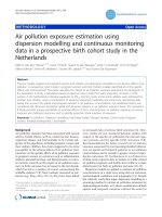
T2 and LTE RF signals in the fixed indoor transmission scenario is shown in Figure 1. The main system parameters of
DVB-T2-Lite and LTE systems, considered in this work,
can be found in Table 2. The DVB-T2-Lite TV signal is
broadcast in a single frequency network (SFN) at a center
frequency of 794 MHz and received by UE1 in a building.
In the same building, LTE femtocells are deployed and the
HeNB provides mobile connectivity in a channel belonging
to Band 20 (from 791 up to 821 MHz). A user of UE2
Polak et al. EURASIP Journal on Wireless Communications and Networking (2015) 2015:114
Page 3 of 14
Table 1 Comparison of explored coexistence scenarios between DVB-T/T2 and LTE systems
Reference Coexistence scenario (TV broadcast scenario) Type of interference
Results
Evaluation parameters
[42]
DVB-T vs. LTE (fixed)
Simulation
SNR, SINR, QoS
[43]
LTE vs. DVB-T (fixed, portable)
Adjacent channel
Simulation
PR, CR
[44]
DVB-T vs. LTE (fixed)
Adjacent channel
Simulation
BER, PF, PR
[45]
DVB-T vs. LTE (fixed)
Intersystem
Simulation
IPL, spectral overlap
[27]
LTE-A vs. DVB-T (fixed)
Intersystem
Simulation
ADL, FO
[46]
LTE vs. DVB-T (fixed)
Intersystem (co-channel)
Measurement
Data throughput, RSRQ
[47]
DVB-T vs. LTE (fixed)
Co-channel
Simulation
I/N, C/(N+I)
[48]
DVB-T/H vs. LTE (fixed)
Co-channel
Measurement
SSIM, QEF, SIR
[30]
LTE vs. DVB-T2-Lite (mobile)
Adjacent channel
Measurement
SDR, QEF, EVM, MER
[31]
DVB-T/T2 vs. LTE (partly mobile, fixed)
Co-channel and adjacent channel Measurement
SDR, BER, EVM, MER
This study
DVB-T2-Lite vs. LTE (fixed)
Co-channel (partial overlapping)
Mutual co-channel
Simulation/Measurement QEF, partly CQI, EVM
Abbreviations: ADL, antenna discrimination loss; PER, packet error ratio; BER, bit error ratio; PF, picture failure; CI, carrier-to-interference ratio; PR, protection ratio;
CR, correction factor; QEF, quasi error-free; CQI, channel quality indicator; QoS, quality-of-service; C/(N+I), carrier-to-noise+interference ratio; RSRQ, reference signal
received quality; EVM, error vector magnitude; SDR, spectral density ratio; FO, frequency offset; SIR, signal-to-interference ratio; IPL, interference power level; SINR,
SIR plus noise-ratio; I/N, interference associated to new sources; SNR, signal-to-noise ratio; MER, modulation error ratio; SSIM, structural similarity.
establishes connection with HeNB at downlink frequency
band from 795 (797.2 MHz) to 805 MHz (817.2 MHz).
We consider that the bandwidth of the LTE signal is 10 or
20 MHz, and intersystem frequency overlapping is from
0.8 up to 3 MHz. Consequently, coexistence between
HeNB (supporting 3GPP LTE Release 9) and DVB-T2-Lite
system can occur. As a specific type of coexistence, a
partial overlapping scenario is assumed. It means that the
channel of the interferer (in this case LTE) partially overlaps with the channel of the victim (in this case DVB-T2Lite) [27]. It is assumed that both UEs are stationary.
4 Simulation and measurement setup
In this section, the simulation method, used to explore
the coexistence of digital TV and mobile RF signals
under outdoor-to-indoor and indoor-to-indoor conditions, is presented. Furthermore, the proposed measurement testbed and its setup, used in this work, are
introduced. The simulation and measurement campaign
consists of the following:
1. Simulation (propagation loss) and measurement of
LTE performance in different locations (indoor and
outdoor environment);
2. Simulation (propagation loss) and measurement of
DVB-T2-Lite performance in different locations
(indoor and outdoor environment);
3. Simulation and measurement of simultaneous
transmission (signal propagation) of both LTE and
DVB-T2-Lite RF signals in order to evaluate the
DVB-T2-Lite
SFN NETWORK
LTE
MACROCELL
(790-798) MHz
LTE
FEMTOCELL
(795-817.2) MHz
(Downlink)
DVB-T2-Lite
Tx
UE1
UE2
LTE
macro eNodeB
Coexistence between DVB-T2-Lite
and LTE services
Figure 1 Unwanted coexistences between DVB-T2-Lite and LTE services at fixed indoor transmission scenario. Supposed scenario where LTE femtocell is
indoors and DVB-T2-Lite signal penetrates from outdoor transmitter and affects performance.
Polak et al. EURASIP Journal on Wireless Communications and Networking (2015) 2015:114
Table 2 DVB-T2-Lite and LTE main system parameters
considered in this study
Definition of parameters
DVB-T2-Lite
Type of FEC scheme
BCH and LDPC Turbo
LTE (Release 9)
FEC code rate
2/3
Type of modulation
16QAM
1/3
QPSK
16QAM
64QAM
Constellation rotation
No
IFFT size
2,048 (2K)
1,024 (10 MHz)
2,048 (20 MHz)
Type of PP pattern
PP2
-
Guard interval duration
28 μs
4.7 μs
Transmission mode
SISO
SISO
Carrier frequency (MHz)
794
Downlink (791 ÷ 821)
Channel bandwidth
8 MHz
10 MHz, 20 MHz
RF power
(0.1 to 5) W
(0.01 to 0.06) W
Channel environment
Outdoor-toindoor
Indoor (indoor-tooutdoor)
FEC decoding method
1D LLR [6]
Max Log-map
Tx antenna height (m)
(above floor)
2
1
Rx antenna height (m)
(above floor)
1
1
LTE user equipment
-
Huawei e389u-15 (LTE UE
category 3)
BCH, Bose-Chaudhuri-Hocquenghem; LLR, log likelihood ratio; FEC, forward
error correction; PP, pilot pattern; IFFT, inverse fast Fourier transform; SISO,
single-input single-output; LDPC, low-density parity-check.
influence of coexistence on the performance of both
systems (on physical layer (PHY) level); and
4. Identification of the noncritical (both systems can
coexist) and critical (partial or full loss of DVB-T2-Lite
and LTE signal) coexistence scenarios for both systems.
4.1 Simulation setup
The considered coexistence scenario was briefly outlined
in the previous section. In this work, we assume that
transmitters and receivers are located on the seventh
floor (the top floor) in the building of Brno University of
Technology (BUT), Faculty of Electrical Engineering and
Communications (FEEC) in Brno. Laboratories of Digital
TV Technology and Radio Communications, and Mobile
Communications of the Department of Radio Electronics
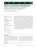
(DREL) are located on this floor. The floor plan of the seventh floor is shown in Figure 2. Approximate dimensions
of the floor are 50 × 25 m. The HeNB is located in the
Laboratory of Mobile Communication Systems (room
7107), and the DVB-T2-Lite transmitter is located outdoor
on the terrace.
Page 4 of 14
The whole simulation model is realized in MATLAB.
Propagation of the LTE and DVB-T2-Lite RF signals are
simulated separately. The simulation of separate propagation loss of LTE and DVB-T2-Lite RF signals will be
used as the reference (no coexistence).
The simulation model consists of three main parts for
both LTE and DVB-T systems. The first part represents
the simulation of a link budget, according to the 3GPP
recommendation for system level simulations [28,29] for
both coexisting systems. Signal strength in the receiver
can be expressed as follows:
P RX ¼ P TX −L TXC þ G TXA −PL þ G RXA −L RXC
ð1Þ
where PTX is transmitter power, LTXC are wiring losses,
GTXA is transmitting antenna gain, GRXA is receiving antenna gain, LRXC are wiring losses, and finally, PRX is received signal level. Path losses in wireless transmission
are denoted as PL (for details see Equation 3). Value of
PTX is known from the transmitter setup. Values of
LTXC, LRXC, GTXA , and GRXA are constants depending on
the used equipment (for details see Subsection 4.2). The
second part represents the validation of obtained results
from the simulation according to the performed measurement and their interpretation in a map. Details are in
Subsections 4.1 and 4.2. The last part compares power
imbalance of tested radio channels and computed
achievable performance of both systems in certain locations. Details are given in Section 5.
The propagation scenario of the LTE RF signal in femtocell involves indoor-to-indoor line-of-sight (LOS) propagation for the same room where HeNB is located (room
7107) and non-LOS (NLOS) for other indoor locations.
Path losses are modeled according to the 3GPP recommendation for indoor LTE femtocell as described in [28],
denoted as UE to HeNB, where UE is inside the same
building as HeNB. In order to model indoor-to-outdoor
propagation from the HeNB to the measurement points on
the terrace, the original equation was extended with outdoor wall penetration loss. On the other hand, the recommendations in [28] are generally valid for frequencies
around 2 GHz, but we exploit an 800-MHz band in this
study. Therefore, it is necessary to perform a correction as
described in [29]. This correction defines the correction
factor for 800 MHz as follows:
PL COR ¼ 20 log10 ðf c Þ
ð2Þ
where fc is carrier frequency in MHz.
The resulting path loss equation is:
PL ¼ 38:46 þ 20 logðd Þ þ 0:7d in þ LP floor
þ q L INwall þ nL OUTwall þ PL COR
ð3Þ
where d is the distance between the HeNB and the UE,
din is indoor propagation distance, LPfloor is penetration
Polak et al. EURASIP Journal on Wireless Communications and Networking (2015) 2015:114
Page 5 of 14
Figure 2 Floor plan and general block diagram. Floor plan of the seventh floor in the building of BUT, FEEC, DREL and general block diagram of
the measurement testbed.
loss due to propagation through the floor (it is equal to
zero because a single-floor propagation scenario is assumed), parameter q is the number of indoor walls
separating the transmitter and receiver, LINwall is the
penetration loss due to walls inside the building, n is the
number of outside walls, LOUTwall is the penetration loss
Polak et al. EURASIP Journal on Wireless Communications and Networking (2015) 2015:114
of the exterior wall, and PLCOR is the frequency correction factor as defined in [29] and shown in Equation 2.
In our case din = d, LPfloor = 0 (single floor), q > 0 (in
the case of the NLOS scenario), LINwall = 5 dB, n is between 0 and 5 (depending on the concrete position on
the floor) and LOUTwall = 10 dB.
The propagation scenario between the DVB-T2-Lite
transmitter and TV receiver is considered as outdoor-toindoor urban femtocell propagation, where the UE is
outside as described in [29]. The DVB-T2-Lite RF signal
attenuation with frequency correction can be calculated
similarly to Equation 3 as:
À
Á
PL ¼ max 15:3 þ 37:6 log10 ðd Þ; 38:46 þ 20 log10 ðd Þ
þ 0:7d in þ LP floor þ q L INwall þ nL OUTwall þ PL COR
ð4Þ
where all variables have the same meaning as in Equation 3.
No fading was included in the data displayed in Figures 3
and 4, however, both fast fading and shadowing were computed according to recommendations in [29].
Figures 3 and 4 show the results of LTE and DVB-T2Lite radio signal propagation obtained from simulation,
respectively. System parameters determined according to
the simulation results prove accessibility of wireless services in all tested locations.
Path loss model data provides the basis for coexistence
simulations. We have provided a detailed description of
LTE and DVB-T2-Lite coexistence in our previous works
[30] and [31]. Based on data collected from the
mentioned measurements, we made a dense description
(linear model) of coexistence. There are two types of input parameters for the models: global and local. The global parameters are mainly represented by the settings of
both systems’ PHY, such as modulation used in DVBT2-Lite, inverse fast Fourier transform (IFFT) size, and
the Forward Error Correction (FEC) code rate of both
systems. Obviously, the overlapping bandwidth is also a
global parameter. Local parameters, used as the model
input, are mainly local power levels of signals, background noise, and the local fading model employed.
These parameters are input into the linear model, which
maps them to the Quality-of-Service (QoS) parameters.
More details can be found in Subsection 5.1.
4.2 Measurement setup
For evaluating the interaction of the described coexistence scenarios between DVB-T2-Lite and LTE RF signals, the same measurement testbed was used as
described in our previous works ([30] and [31]). The
whole measurement campaign was implemented on the
seventh floor of the building of BUT, FEEC, DREL (see
Figure 2). The measurement campaign and the basic
principle of our measurement method are as follows.
Page 6 of 14
Firstly, the parameters and performance of the 3GPP
LTE network are measured in different locations on the
seventh floor. At the time of LTE measurement, T2-Lite
services were not broadcasted. The HeNB is located in
room 7107, and its antennas are placed on top of a table
(approximately 1 m above the floor). The HeNB consists
of two main hardware components, namely a PC with
the Fedora Linux operating system and universal software radio peripheral (USRP) N210 from Ettus,
equipped with an SBX daughter card. The PC runs the
commercial software package Amari LTE [32], implementing functions of LTE Mobile Management Entity
(MME) and eNB (both are 3GPP LTE Release 9 compliant). A detailed configuration of the LTE network is
summarized in Table 2. The receiving UE is Huawei
e398-u15 (Huawei, Shenzhen, China) (LTE UE Cat. 3)
[33], connected via USB port to a laptop equipped with
the Rohde & Schwarz drive test software ROMES4. For
receiving LTE services, the TechniSat Digiflex TT1 mobile antenna (TechniSat, Vulkaneifel, Germany) was used
(G < 2 dBi). The length of its feed line is 3 m. The UE is
connected to an external antenna placed on a wooden
cart approximately 1.0 m above the floor. We set up the
connection between UE and HeNB and performed simultaneous full buffer transmissions in uplink and downlink. The measurement was carried out in fixed points
distributed on the seventh floor as shown in Figure 2.
The receiving antenna was kept still for 2 min at each
measurement point and in each location we have collected approximately 100 samples of each network parameter of interest (including RSS, Channel Quality Indicator
(CQI), Error Vector Magnitude (EVM), etc.).
Secondly, we have measured the performance of the
DVB-T2-Lite signal in different locations on the seventh
floor. At the time of T2-Lite measurement, LTE services
were not provided. By using the R&S single frequency unit
(SFU) broadcast test system, an appropriate video transport
stream for portable TV scenarios was generated. Then, the
DVB-T2-Lite complete system configuration was set up,
and the output signal was RF modulated (to the frequency
of 794 MHz). For its amplification, a custom-built RF
power amplifier (PA), based on hybrid module Mitsubishi
RA20H8087M (Mitsubishi Electric, Tokyo, Japan) [34], was
applied. This RF three-stage module is primarily destined
for transmitters using FM modulation that operate in the
range 806 up to 870 MHz, but it may also be applied in linear systems by setting the proper drain quiescent current
with externally settable gate voltage. The PA was assembled
according to the recommendations of the producers and
thoroughly tested. The comprehensive measurement demonstrates that this PA can be used in a wider band, circa
from 650 to 900 MHz, and can be used in the presented
coexistence test. The gain of the PA strongly varies in the
introduced frequency range from 36 to 50 dB, but in a
Polak et al. EURASIP Journal on Wireless Communications and Networking (2015) 2015:114
Page 7 of 14
250
−20
−30
200
Dimension Y [dm]
−40
−50
150
−60
100
−70
−80
50
−90
0
0
100
200
300
400
Dimension X [dm]
500
600
−100
Figure 3 Simulation of LTE RF signal propagation. The HeNB is located in room 7107 (the blue triangle), and network parameters are as described in
Table 2. The path loss model was adopted from [28] and extended for the 800-MHz band according to [29] (see Equations 2 and 3). All values are in dBm.
narrow band, the gain is quite stable (max. 1.5 dB in 10
MHz bandwidth). The maximum output power of this
amplifier is around 30 W. However, we practically used
only 1 W (5 W was used for the scenario where power imbalances were equal to 20 dB) with quiescent drain current
4 A, gate bias voltage 4.3 V, and supply voltage 13.8 V to
achieve high linearity for reliable application in the
mentioned setup. Accordingly, the power efficiency in
this setting is only 2%. On the other hand, reaching linearity is the fundamental parameter which needs to be
set for minimizing any nonlinear distortion. For the
used testing DVB-T2-Lite frequency (794 MHz), the
250
−20
−30
200
Dimension Y [dm]
−40
−50
150
−60
100
−70
−80
50
−90
0
0
100
200
300
400
Dimension X [dm]
500
600
−100
Figure 4 Simulation of DVB-T2-Lite RF signal propagation. The DVB-T2-Lite transmitter is located on the terrace (the blue triangle), and its parameters are
described in Table 2. The path loss model was adopted from [28] and extended for the 800-MHz band according to [29] (see Equations 2 and 4). All values
are in dBm.
Polak et al. EURASIP Journal on Wireless Communications and Networking (2015) 2015:114
measured 1 dB compression of this PA is 37.9 dBm
(6.2 W), two-tone third-order intermodulation distortion (IMD3) (tone offset 1 MHz) is better than −38
dBc at the output power of 1 W, which corresponds
to output intercept point (OIP3) 49 dBm. Between
the PA and the antenna, there is an attenuator in the
signal path. It serves as PA protection in the case of
antenna switch-off or strong reflections in the antenna near the field. The JFW Industries 50BR-104 N
attenuator (JFW Industries, Indianapolis, IN, USA)
was used which was set to 0 dB during measurement.
The mentioned nonlinear distortions caused by PA
are not considered in our simulation model.
The used antenna is a multi-element Yagi antenna
(Gmax = 15.4 dBi) whose horizontal radiation pattern is
shown in Figure 2. The feed line for the TV transmitter
chain is a coaxial cable RG58 C/U which has a power
loss of approximately 0.35 dB/m on the tested bandwidth. Attenuation of the auxiliary connection between
‘N’ and ‘BNC’ connectors is approximately 0.5 dB/m.
For the LTE system (HeNB), the Sectron AO-ALTEMG5S antenna (Sectron Inc., Ormond Beach, FL, USA)
was used. In our case, it was used as an omnidirectional antenna in vertical polarization (G < 3 dBi). After setting up
the testbed, we moved with the Sefram 7866HD-T2
analyzer (Sefram Instruments and Systems, Saint-Étienne,
France) to measure the received TV signal through all
measuring points. The same antenna setup was used as is
outlined above for LTE downlink. Once again, we spent 2
min at each measurement point for correctly evaluating the
performance of the received DVB-T2-Lite RF signal (to
avoid fast fading by averaging).
Figures 5 and 6 show measured and extrapolated values
of RSS. Figure 5 shows the results of LTE radio signal
propagation while Figure 6 shows the results of T2-Lite
radio signal propagation obtained from measurement. System parameters determined according to the simulation results proves accessibility of wireless service in all tested
locations. As we can see, results from measurement, shown
in Figures 5 and 6, correspond with simulation results
shown in Figures 3 and 4. This experimental result proves
our simulation technique valid for coexistence applications.
Afterwards, the whole measurement campaign was repeated, but now both wireless services (DVB-T2-Lite
and LTE) were provided together at the same time. The
above outlined QoS parameters of both services, caused
by coexistence between them, were measured separately
with Rohde & Schwarz devices.
5 Experimental results
5.1 Parameters to evaluate the performance of DVB-T2Lite and LTE
Before evaluating and discussing the obtained results, it is
necessary to briefly define the most important measured
Page 8 of 14
parameters which were used to evaluate the performance
of T2-Lite and LTE systems. To evaluate the quality of the
received and decoded TV services, the Quasi Error-Free
(QEF) reception conditions were monitored. QEF is a
minimal limit defined in the DVB-T2-Lite standard for
achieving video service availability without noticeable errors in the video. To fulfill such requirements, the bit
error ratio (BER) after FEC decoding must be less than or
equal to 1 × 10⁻⁷ [6].
To evaluate the performance of LTE, the RSS, CQI,
and EVM parameters were monitored. The CQI contains information sent from the UE to the HeNB to indicate a suitable downlink transmission data rate. It is
based on the observed signal-to-interference-plus-noise
ratio (SINR) and used by the HeNB for downlink scheduling and link adaptation [28]. There are 15 different
CQI values (numbered from 1 up to 15). The connection
between them and the modulation scheme can be found
in [35] (Table 7.2.3-1).
EVM, the second parameter, is a measure used to
quantify the performance of an LTE communication
link. It is the RMS value of the distance in the IQ constellation diagram between the ideal constellation point
and the point received by the receiver. For each modulation, there is a defined EVM limit, for which the transmitted signal has an acceptable quality. This limit is
equal to 17.5% for quadrature phase-shift keying
(QPSK), 12.5% for quadrature amplitude modulation
(16QAM), and 8.0% for 64QAM [11,28].
5.2 DVB-T2-Lite and LTE performance evaluation
In Subsection 4.1, it has been mentioned that the linear
coexistence model maps input parameters from simulations and measurements to the area of QoS states. We
have defined the following QoS states for the coexisting
services. For DVB-T2-Lite, there are two states: correct
reception and no reception. In the case of correct reception, the above defined condition for QEF reception is
satisfied. For LTE, we have defined four QoS states
which differ in user bitrate and potential radio access
network (RAN) throughput. These parameters obviously
increase with M in M-QAM modulation of subcarriers.
The LTE system changes the modulation scheme adaptively according to the channel parameters (e.g., CQI,
EVM). To be more precise, the highest useable M-state
for the defined interfered radio channel sets the QoS
state of LTE. Four states correspond to maximal M
equaling 64 (64QAM), 16 (16QAM), and 4 (QPSK), and
the state when providing LTE services is not possible.
The considered coexistence scenarios between DVB-T2Lite and LTE services were described above. Furthermore,
we also consider various system parameters. The complete
list of assumed scenarios is clearly summarized in Table 3.
There are three main parameters: bandwidth of the LTE RF
Polak et al. EURASIP Journal on Wireless Communications and Networking (2015) 2015:114
Page 9 of 14
250
−20
−30
200
Dimension Y [dm]
−40
−50
150
−60
100
−70
−80
50
−90
0
0
100
200
300
400
Dimension X [dm]
500
600
−100
Figure 5 Measurement of LTE RF signal propagation. The HeNB is located in room 7107 (the blue triangle), and network parameters are
described in Table 2. The measurement was carried out in highlighted points and extrapolated using MATLAB. All values are in dBm.
channel (marked as BLTE), overlap of coexisting channel
(BOVER), and the power imbalance between transmitted
powers (ΔP).
The last one is calculated as follows:
ΔP ½dB ¼ EIRP LTE −EIRPTV
ð5Þ
where equivalent isotropically radiated power (EIRP)LTE
and EIRPTV denote the channel power of LTE and T2Lite RF signals, respectively.
Figure 7 shows the simulated results of six map representations of QoS states in DVB-T2-Lite and LTE systems. Each map (from (a) to (f )) corresponds to the
250
−20
−30
200
Dimension Y [dm]
−40
−50
150
−60
100
−70
−80
50
−90
0
0
100
200
300
Dimension X [dm]
400
500
600
−100
Figure 6 Measurement of DVB-T2-Lite RF signal propagation. The HeNB is located in room 7107 (the blue triangle), and network parameters are
described in Table 2. The measurement was carried out in highlighted points and extrapolated using MATLAB. All values are in dBm.
Polak et al. EURASIP Journal on Wireless Communications and Networking (2015) 2015:114
Table 3 Variable parameters of DVB-T2-Lite and LTE for
assumed coexistence scenarios
Map
BLTE (MHz)
BOVER (kHz)
Power imbalance (ΔP) (dB)
a
10
800
0
b
20
800
0
c
20
1,600
0
d
20
1,600
−10
e
20
1,600
−20
f
20
3,000
0
considered system parameters and coexistence scenarios
which are presented in Table 3. In the floor plan of the
university, for each point in the explored areas, the state
of both coexisting systems is indicated.
Performances of T2-Lite and LTE systems can be
clearly explained in the legend of Figure 7. Four colors
represent the LTE maximum useable internal modulations: orange - 64QAM, yellow - 16QAM, and green QPSK, and unavailable LTE services are indicated by a
cyan color. The performance of DVB-T2-Lite services is
indicated by a crosshatch in the same maps. The presence of a hatch means that the QEF limit of mobile TV
reception is fulfilled. For a better explanation of the obtained results, we describe a specific example.
For example, we consider a partial overlapping coexistence scenario between T2-Lite and LTE services when
BLTE = 20 MHz, BOVER = 1,600 kHz, and ΔP is equal to
0 dB (see line (c) in Table 3). Performances of coexisting
systems for these parameters are plotted in Figure 7c. As
can be seen from the legend, at the 1.6-MHz channel
overlapping, in the LTE system, only sub-frames using
QPSK and 16QAM modulations will be received and
demodulated correctly (yellow color in the legend) on
the left side of the corridor. It means that only at these
modulations EVM errors do not exceed the permitted
limit values [11]. In the remaining rooms, the highest
64QAM modulation (highlighted by orange color) is
used in the LTE system. Consequently, CQI values can
be 10 or higher. Furthermore, this field also indicates
that the services of DVB-T2-Lite are highly noised and
conditions for QEF reception are not fulfilled (there are
no hatched parts). The situation result is the opposite on
the terrace where DVB-T2-Lite services are broadcasted.
At this place, the provided LTE services are not available
(blue color). In this case, the LTE system could not decode the received signal and the CQI value is the lowest.
Interestingly, in the small corridor, located between the
terrace and the main floor corridor, partial coexistence
between T2-Lite and LTE systems is possible. It means
that at this place, both wireless systems can coexist. The
QEF limit for DVB-T2-Lite is still fulfilled. However, in
the LTE system, only sub-frames using QPSK modulation can be successfully processed. Hence, the CQI
Page 10 of 14
indicator values will be in the range from 1 up to 6 [35].
Similar graphical representations of considered coexistences are plotted in Figure 7a,b,c,d,e,f.
Now, let us focus on the first two charts (see Figure 7a,b).
Their parameters differ just in the used LTE channel bandwidth (BOVER), but the disparity in state map is high. From
the point of BLTE = 20 MHz LTE channel (see Figure 7b),
the 800 kHz interference bandwidth is quite narrow and almost no effect can be seen on LTE inside the building. Outside, LTE works correctly with 16QAM. However, when
BLTE is equal to 10 MHz (see Figure 7a), then the LTE
channel, affected by the same interference bandwidth
(800 kHz), is occupied by almost twice the interfering
RF power. In this case, the LTE system still works correctly, but only 16QAM and QPSK (indoor/outdoor)
modulations can be used. Furthermore, mobile TV reception is also more affected by LTE services because
LTE interference power is concentrated into a narrower
channel. In real RANs, where power limits are more
likely set to 1 Hz of occupied bandwidth, the impact on
the reception of mobile TV services would be the same.
The influence of channels overlapping and the effect of
different EIRP unbalances could be investigated from
the remaining charts.
Figure 8 shows six map representations of QoS states
in DVB-T2-Lite and LTE systems from measurements.
In general, in most measuring points, the defined states
of QoS correspond with simulation results. However,
there are some minor differences caused by the accumulation of two types of uncertainties. The first ones are
caused by path loss channel modeling, and these are
even multiplied by the second ones, caused by the proposed linear model. Most probably, the largest influences
are due to inhomogeneity in walls (doors, windows and
various types of material), underestimation of noise level,
and impact of multipath propagation. It is obvious that
the simulation and measurement results in scenario (e)
have the lowest difference. This state is caused by the
highest signal level (in the above mentioned scenario)
which brings reduction of noise background impact and
increase the influence of intersystem jamming simultaneously for all transmission paths.
6 Conclusions
The main aim of this paper is to investigate the impact
of coexisting DVB-T2-Lite and LTE systems in a shared
frequency band on their system performances in the
outdoor-to-indoor reception scenario. To be more precise, a scenario was considered where an indoor LTE
femtocell (HeNB) and outdoor-to-indoor DVB-T2-Lite
services are provided in an 800-MHz frequency band
(see Figures 1 and 2). We have performed separate simulations of both LTE and DVB-T2-Lite RF signal propagation
in MATLAB. Further, we have carried out measurements
Polak et al. EURASIP Journal on Wireless Communications and Networking (2015) 2015:114
a)
b)
c)
d)
e)
f)
Page 11 of 14
Figure 7 Simulation - the map representation of QoS states of coexisting systems (a-f). Specific map parameters are summarized in Table 3.
Polak et al. EURASIP Journal on Wireless Communications and Networking (2015) 2015:114
a)
b)
c)
d)
e)
f)
Page 12 of 14
Figure 8 Measurement - the map representation of QoS states of coexisting systems (a-f). Specific map parameters are summarized in Table 3.
Polak et al. EURASIP Journal on Wireless Communications and Networking (2015) 2015:114
of both wireless systems in order to evaluate the reliability
of the simulation model. Results are shown in Figures 3, 4,
5, 6 and correlate well.
According to the achieved results in our previous
works ([31] and [28]), we have created a linear model to
map outputs of the path loss model to defined QoS
states. This model considers the relation between the
value of RF channels overlapping and the power imbalance of the investigated radio channels. A detailed description is outlined in Subsection 4.1.
The presented results are expressed in a set of maps
(floor plans of the building) with colored areas which determine availability or non-availability of coexisting services and achievable performance. Specific values of
these parameters in the considered scenarios are presented in Table 3. The effect of coexistence on valid signal reception is quantified by the change of used
modulation scheme and simultaneous availability of services. A detailed description of the color maps is described in Section 5. In the proposed linear model for
both systems, we assume good channel conditions (global
parameters): signal-to-noise ratio (SNR) ≥35 dB for both
systems and also no multipath propagation and no
Doppler frequency have been set. Once again, the proposed linear model was proved by measurements (see
Figures 7 and 8). In several cases, less correspondence
between the simulation and measurement results is
explained.
An analysis of the obtained results from the considered coexistence scenarios leads to the following general
conclusions:
a) The impact of DVB-T2-Lite system performance on
the LTE system performance and vice versa in their
co-channel coexistence scenario in a shared frequency
band highly depends on the level of their channels
overlapping and on the power imbalance between RF
signals.
b) The outdoor-to-indoor penetration of the T2-Lite
signal is highly critical on indoor-to-indoor reception
of LTE services when the power imbalance between
the RF levels is high. In these cases, the T2-system
acts as a co-channel interferer to indoor LTE femtocell
and vice versa.
c) Digital TV fixed indoor reception is more vulnerable
to interferences than fixed outdoor reception.
The main aim of our future work will be to extend our
proposed linear coexistence model with more global parameters (different kinds of fading channel models and
Doppler shift [36-39]) for more realistic modeling of
different coexistence scenarios between DVB-T2-Lite
and LTE services and vice versa. Moreover, in our future work, we will consider a larger range of system
Page 13 of 14
parameters (code rate, IFFT length, guard interval,
and higher M-QAM modulations and bandwidth)
[40,41].
Competing interests
The authors declare that they have no competing interests.
Acknowledgement
This work is supported by the Cluster for Application and Technology
Research in Europe on Nanoelectronics (CATRENE) under the project named
CORTIF CA116 - Coexistence of Radio Frequency Transmission in the Future,
the MEYS of the Czech Republic no. LF14033, no. CZ.1.07/2.3.00/20.0007 and
CZ.1.07/2.3.00/30.0005, and finally by the BUT project no. FEKT-S-14-2177.
The described research was performed in laboratories supported by the SIX
project; no. CZ.1.05/2.1.00/03.0072, the operational program Research and
Development for Innovation. Research described in this paper was financed
by Czech Ministry of Education in frame of National Sustainability Program
under grant LO1401. For research, infrastructure of the SIX Center was used.
Received: 31 October 2014 Accepted: 24 March 2015
References
1. Z Raida et al., Communication subsystems for emerging wireless
technologies. Radioengineering 21(4), 1036–1049 (2012)
2. T Yos, Y Wu, N Hur, T Ikeda, P Xia, FOBTV: worldwide efforts in developing
next-generation broadcasting system. IEEE Trans. on Broadcasting
60(2), 154–159 (2014)
3. L Klozar, L Polak, O Kaller, J Prokopec, Effect of Co-Existence Interferences
on QoS of HSPA/WCDMA Mobile Networks, in Proceedings of the 23rd IEEE
International Conference Radioelektronika 2013, 2013, pp. 312–315
4. W Sami, How can Mobile and Broadcasting Networks use Adjacent Bands?
in EBU Technical Review, 2011, pp. 1–20
5. Digital Video Broadcasting (DVB), Framing Structure, Channel Coding, and
Modulation for Digital Terrestrial Television Broadcasting System (DVB-T2),
2012. ETSI EN 302 755 V1.3.1
6. Digital Video Broadcasting (DVB), Implementation Guidelines for a Second
Generation Digital Terrestrial Television Broadcasting System (DVB-T2),
2012. 2012. ETSI TS 102 831 V1.2.1
7. ITU-Rec, Frequency and Network Planning Aspects of DVB-T2, 2012.
ITU-R BT.2254
8. DA Samo, M Slimani, G Baruffa, L Rugini, A performance study of DVB-T2 and
DVB-T2-Lite for mobile reception. Digital Signal Processing 37(2), 35–42 (2015)
9. C Regueiro, U Gil, M Velez, I Eizmendi, P Angueira, Field trials-based
planning parameters for DVB-T2 indoor reception. IEEE Trans on Broadcasting.
(2015). doi:10.1109/TBC.2015.2400814)
10. Digital Video Broadcasting (DVB), Framing Structure, Channel Coding and
Modulation for Digital Terrestrial Television, 2009. ETSI EN 300 744 v1.6.1
11. 3GPP, 3rd Generation Partnership Project, Evolved Universal Terrestrial Radio
Access (E-UTRA); User Equipment (UE) Radio Transmission and Reception
(Release 8), 2010. Tech. Specification 3GPP TS 136.101 V8.9.0
12. E Dahlman, 3G Evolution: HSPA and LTE for Mobile Broadband, 2nd edn.
(Academic Press, Oxford, 2008)
13. D Astely, E Dahlman, A Furuskar, Y Jading, M Lindstrom, S Parkvall, LTE:
the evolution of mobile broadband. IEEE Communication Magazine
47(4), 44–51 (2009)
14. Rohde & Schwarz, Coexistence digital TV and LTE (Rohde & Schwarz, 2012),
/>application_notes/1ma176/1MA176_3e_coexistence_digital_TV_and_LTE.pdf
15. P Stavroulakis, Interference Analysis and Reduction for Wireless Systems
(Artech House, Norwood, 2003)
16. F Gleissner, S Hanus, Co-channel and adjacent channel interference
measurement of UMTS and GSM/EDGE systems in 900 MHz radio band.
Radioengineering 17(3), 74–80 (2008)
17. J Mikulka, S Hanus, Bluetooth and IEEE 802.11b/g coexistence simulation.
Radioengineering 17(3), 66–73 (2008)
18. B Han, W Wang, Y Li, M Peng, Investigation of interference margin for the
co-existence of macrocell and femtocell in orthogonal frequency division
multiple access systems. IEEE Systems Journal 7(1), 59–67 (2013)
Polak et al. EURASIP Journal on Wireless Communications and Networking (2015) 2015:114
19. A Lourerio, D Callegos, G Caldwell, Interference Analysis on UMTS-2100
Co-Existence with GSM-1900, in Proceedings of the 74th IEEE VTC FALL 2011,
2009, pp. 1–4
20. WA Hassan, TA Rahman, Coexistence model for compatibility between
IMT-advanced and other wireless communication services. Wireless Personal
Communications 79(3), 2025–2039 (2014)
21. MH Ng, S-D Lin, J Li, S Tatesh, Coexistence studies for 3GPP LTE with other
mobile systems. IEEE Communications Magazine 47(4), 60–65 (2009)
22. D Lee, GY Li, S Tang. Inter-Cell Interference Coordination for LTE Systems,
in IEEE GLOBECOM 2012, 4828–4833 (2012)
23. T Cai, J Deng. Coexistence Study and Interference Analysis in LTE Networks,
in IEEE International Conference ICCECT 2012, 751–754 (2012)
24. L Tytgat, O Yaron, S Pollin, I Moerman, P Demeester, Avoiding collisions
between IEEE 802.11 and IEEE 802.15.4 through coexistence aware clear
channel assessment. EURASIP Journal on Wireless Communications and
Networking 2012, 137 (2012)
25. M Boujelben, S Benrejeb, S Tabbane, A Comparative Study of Interference
Coordination Schemes for Wireless Mobile Advanced Systems, in The 2014
International Networks, Computers and Communications Symposium (ICNC
2014), 2014, pp. 1–5
26. D Chen, T Jiang, Z Zhang, Frequency partitioning methods to mitigate crosstier interference in two-tier femtocell networks. IEEE Trans on Vehicular Technology, 2015. doi:10.1109/TVT.2014.2335251
27. ZA Shamsan, LTE-Advanced Compatibility with Digital Broadcasting Receiver
at 800 MHz, in 2013 Saudi International Electronics, Communications and
Photonics Conference (SIECPC), 2013, pp. 1–4
28. 3GPP, 3rd generation partnership project, Technical specification group
radio access network; evolved universal terrestrial radio access (E-UTRA);
further advancements for E-UTRA physical layer aspects (Release 9), March
2010. Tech. Report 3GPP TR 36.814 V9.0.0, />36814-900.pdf
29. 3GPP, 3rd generation partnership project, Technical specification group
radio access network; evolved universal terrestrial radio access (E-UTRA);
study on LTE device to device proximity services-radio aspects (Release 12),
November 2013. Tech. Report 3GPP TR 36.843 V12 .0.0, http://
www.3gpp.org/dynareport/36843.htm
30. L Polak, O Kaller, L Klozar, J Prokopec, Exploring and Measuring the CoExistence Between LTE and DVB-T2-Lite Services, in Proceedings of the 36th
International Conference on Telecommunications and Signal Processing (TSP)
2013, 2013, pp. 316–320
31. L Polak, O Kaller, L Klozar, J Sebesta, T Kratochvil, Mobile communication
networks and digital television broadcasting systems in the same
frequency bands - advanced co-existence scenarios. Radioengineering
23(1), 375–386 (2014)
32. Software package Amari LTE. Amari LTE 100/Amari OTS 100 Software 4G
network on PC. Online on: < />33. M Slanina, L Klozar, S Hanus, Practical Measurement of Data Throughput in
LTE Network Depending on Physical Layer Parameters, in Proceedings of the
24th International Conference Radioelektronika, 2014, pp. 1–4
34. RA20H8087M. RF MOSFET module 806-870 MHz 20 W 12.5 V, 3 Stage
Amplifier for Mobile Radio. Data Sheet. Mitsubishi Electric Corporation,
July 2011, />180155_RA20H8087M.pdf
35. 3GPP, 3rd generation partnership project, Technical specification LTE;
evolved universal terrestrial radio access (E-UTRA); physical layer procedures
(Release 8), October 2009. Tech. Specification 3GPP TS 136 213 V8.8.0,
/>36. J Milos, S Hanus, Performance analysis of PCFICH and PDCCH LTE control
channels. Radioengineering 23(1), 445–451 (2014)
37. L Polak, T Kratochvil, Analysis and simulation of the transmission distortions
of the mobile digital television DVB-SH part 2: satellite mode DVB-SH-B with
TDM. Radioengineering 21(1), 126–133 (2012)
38. L Polak, T Kratochvil, Exploring of the DVB-T/T2 Performance in Advanced
Mobile TV Fading Channels, in Proceedings of the 36th International
Conference on Telecommunications and Signal Processing (TSP) 2013, 2013,
pp. 768–772
39. L Polak, O Kaller, L Klozar, J Sebesta, T Kratochvil, Exploring and measuring
possible co-existences between DVB-T2-lite and LTE systems in ideal and
portable fading channels. Journal of Applied Research and Technology
13(1), 32–44 (2015)
Page 14 of 14
40. H Hong, H Son, Y Chong, Protection Ratio Between DVB-T2 and LTE System,
in 2014 Information and Communication Technology Convergence (ICTC),
2014, pp. 792–793
41. M Fuentes, C Garcia-Pardo, E Garro, D Gomez-Barquero, N Cardona,
Coexistence of digital terrestrial television and next generation cellular
networks in the 700 MHz band. IEEE Wireless Communications
21(6), 63–69 (2014)
42. A Guidotti, D Guiducci, M Barbiroli, C Carciofi, P Grazioso, G Riva,
Coexistence and Mutual Interference Between Mobile and Broadcasting
Systems, in Proceedings of the 73rd IEEE Vehicular Technology Conference
(VTC Spring), 2011, pp. 1–5
43. K Sakic, S Grgic, The Influence of the LTE System on the DVB-T Reception, in
Proceedings of the 52nd International Symposium ELMAR, 2010, pp. 235–238
44. G Baruffa, M Femminella, F Mariani, G Reali, Protection ratio and antenna
separation for DVB-T/LTE coexistence issues. IEEE Communications Letters
17(8), 1588–1591 (2013)
45. H Bawab, P Mary, J-F Hélard, YJ Nasser, O Bazzi, Global Ergodic Capacity
Closed-Form Expression of Coexisting DVB-LTE-Like Systems, in 2014 IEEE
VTC Spring, 2014, pp. 1–5
46. A Tekovic, G Simac, K Sakic, LTE Downlink System Performance
Measurement with Intersystem Interference Caused by DVB-T Signal,
in Proceedings of the 54th International Symposium ELMAR, 2012,
pp. 255–258
47. A De Vita, D Milanesio, B Sacco, A Scotti, Assessment of interference to the
DTT service generated by LTE signals on existing head amplifiers of
collective distribution systems: a real case study. IEEE Trans. on Broadcasting
60(2), 420–429 (2014)
48. L Polak, O Kaller, L Klozar, J Prokopec, Influence of Mobile Network
Interfering Products on DVB-T/H Broadcasting Services, in Proceedings of the
5th IEEE International Conference Wireless Days 2012, 2012, pp. 1–5
Submit your manuscript to a
journal and benefit from:
7 Convenient online submission
7 Rigorous peer review
7 Immediate publication on acceptance
7 Open access: articles freely available online
7 High visibility within the field
7 Retaining the copyright to your article
Submit your next manuscript at 7 springeropen.com