MODELING OF INTERNAL FAULTS IN THREE PHASE THREE WINDING TRANSFORMERS FOR DIFFERENTIAL PROTECTION STUDIES (TQL)
Bạn đang xem bản rút gọn của tài liệu. Xem và tải ngay bản đầy đủ của tài liệu tại đây (2.04 MB, 80 trang )
MODELING OF INTERNAL FAULTS IN THREE-PHASE
THREE-WINDING TRANSFORMERS FOR
DIFFERENTIAL PROTECTION STUDIES
Didik Fauzi Dakhlan
(1390015)
Delft University of Technology
Faculty of Electrical Engineering, Mathematics and Computer Science
June 2009
MODELING OF INTERNAL FAULTS IN THREE-PHASE
THREE-WINDING TRANSFORMERS FOR
DIFFERENTIAL PROTECTION STUDIES
MSc Graduation Thesis of
Didik Fauzi Dakhlan
(1390015)
Thesis Committee:
Dr. ir. M. Popov
Prof. Dr. J.J. Smit
Dr. ir. P. Bauer
Delft University of Technology
Faculty of Electrical Engineering, Mathematics and Computer Science
Electrical Power Systems
June 2009
2
Acknowledgements
First of all, I would like to give thanks to God for making it possible for me to experience this
great opportunity.
Special thanks to my supervisor Dr. ir. M. Popov for his support, help, patience, advices, and
availability. He has been excellent mentor during this thesis project. My very personal thanks
are directed towards Professor Dr. J.J Smit for his agreement with PLN that give me
opportunity to study in TU Delft. I would also like to thank Dr. ir. P. Bauer for his availability
to take place in my thesis committee.
Also for my PLN colleagues at TU Delft, , thank you guys for helping me in the last two years,
guiding me to finish this master course, and also sharing your knowledge with nice and
warm discussion. It’s a great, valuable and unforgettable experience to working and studying
with amazing friends like you all. Thanks you also to my colleagues at PLN, who help me for
all the valuable data and discussion about the transformer protection technology.
Finally, I will like to thank my family, my wife Lian and my beautiful daughter Narina, for
supporting me in every situation and condition, for being my number one supporters in up
and down, my regrets and sorry to both of you for my absent at your side when you need
most.
Didik Fauzi Dakhlan
3
Table of Content
Acknowledgements ..................................................................................................... 3
Table of Content.......................................................................................................... 4
I. INTRODUCTION ................................................................................................. 5
1.1.
Power Transformer, Faults, and Transformer Protection System ............... 5
1.2.
Problem Definition ....................................................................................... 6
1.3.
Objectives the Present Study ...................................................................... 6
1.4.
Thesis Layout .............................................................................................. 7
II.
PROTECTION SYSTEM OF TRANSFORMER ................................................... 8
2.1.
Introduction.................................................................................................. 8
2.2.
PLN Transformer Protection System Requirements ................................... 9
2.3.
Non electrical Protection............................................................................ 11
2.4.
Electrical Protection................................................................................... 14
III.
TRANSFORMER MODELING ON ATPDraw................................................ 24
3.1.
Introduction................................................................................................ 24
3.2.
BCTRAN Modeling .................................................................................... 24
3.3.
Electrical System Power Component ........................................................ 28
3.4.
Verifying the Model.................................................................................... 33
IV.
TRANSFORMER INTERNAL FAULT MODELING ....................................... 36
4.1.
Introduction................................................................................................ 36
4.2.
Matrix Representation of Transformers ..................................................... 36
4.3.
Modeling Principles ................................................................................... 39
4.3.1.
Direct Self and Mutual Impedance Calculation Method..................... 40
4.3.2.
Leakage Impedance Calculation by Using Leakage Factor .............. 43
V.
SIMULATION AND ANALYSIS ..................................................................... 53
5.1.
Introduction................................................................................................ 53
5.2.
External Fault ............................................................................................ 53
5.3.
Internal Fault.............................................................................................. 59
5.3.1.
Primary Winding Fault ....................................................................... 61
5.3.2.
Secondary Winding Fault................................................................... 64
5.3.3.
Tertiary Winding Fault........................................................................ 72
VI.
CONCLUSIONS AND RECOMMENDATIONS ............................................. 75
6.1.
Introduction................................................................................................ 75
6.2.
Conclusions ............................................................................................... 75
6.3.
Recommendation ...................................................................................... 75
References................................................................................................................ 77
Abbreviation .............................................................................................................. 79
Appendix : Transformer Data .................................................................................... 80
4
I. INTRODUCTION
1.1. Power Transformer, Faults, and Transformer Protection
System
The power transformer is one of the most important primary piece of equipment of the
electric power system. The development of modern power systems has been reflected in the
advances in transformer design. This has resulted in a wide range of transformers with sizes
ranging from a few kVA to several hundred MVA being available for use in a wide variety of
applications.
Different faults can occur inside the transformer and at the electrical system where the
transformer is connected. Transformer faults can be divided into two classes: external and
internal faults.
External faults are those faults that happen outside the transformer:
overloads, overvoltage, under frequency, external system short circuits. The internal faults
occur within the transformer protection zone such as incipient fault (overheating,
overfluxing, overpressure) and active faults (turn-to-earth, turn-to-turn, tank fault, core
fault).
The transformer protection is an essential part of overall system protection strategy.
Moreover, transformers have a wide variety of features, including tap changers, phase
shifters and multiple windings, that require special consideration in the protective system
design.
The combination of electrical and non electrical protection system is installed to protect the
transformer due to those all possible faults. To reduce the effects of thermal stress and
electrodynamic forces, it is advisable to ensure that the protection package used minimises
the time for disconnection in the event of a fault occurring within the transformer.
5
1.2. Problem Definition
A lot of faults can happen at the power transformer. The transformer protection must
isolate and clear the fault fast and correctly. One of the main protections of a transformer is
differential relay. It works for internal faults of the transformer e.g. turn-to-earth and turnto-turn fault of the transformer winding.
The internal faults of the transformer can be modeled by modifying the coupled inductance
matrix of the transformer. If there is an internal fault of the transformer, the coupled
inductance matrix will change due to the fault point. This new matrix is depended on the
location of fault and type of faults.
Simulation of the faulty transformer will produce the faulty waveform that can be used to
test the correctness and sensitivity of the differential protection.
1.3. Objectives the Present Study
To support the testing of the protection system from transformer internal faults, the above
mentioned modeling of internal faults is built and simulation using real system is done to
make the fault waveform.
To analyze and verify the model, the no-load test and load/copper losses test result from the
transformer can be used. The geometric quantities of the transformer and the impedance
test result also can be used to analyze and verify the model.
The calculation of the new transformer parameters due to internal faults has to be used to
make the new model of the transformer. Finally, simulations using real system data should
be introduced to know the protection system behavior due to the internal faults.
In particular, the following steps have to be taken:
•
Collecting the available data of the transformer: geometric quantities of the
transformer, factory acceptance test result (no-load losses and copper/load
losses test), etc.
•
Based on the test result of the transformer : modeling the healthy transformer
6
•
Verification of the model by simulation of test which has been done in factory
acceptance test e.g. load losses and no-load losses test.
•
Verification of the transformer coupled inductance matrix by using geometric
quantities of the transformer.
•
Development of new coupled inductance matrix due to internal faults of the
transformer.
•
Connection the transformer to the model of the real system in the field.
•
Simulation of the external and internal faults (turn-to-earth and turn-to-turn
winding fault)
•
Analyzing the fault waveform which produced by the simulation for protection
system studies.
1.4. Thesis Layout
This thesis introduces the reader to the theory of faults in the transformer and the
protection due to those faults. In subsequent chapters, the healthy transformer modeling is
built using BCTRAN routine and the model is verified by manual calculation and simulation of
short and open circuit test during Factory Acceptance Test (FAT) of the transformer. Then,
the new models of the faulty transformer due to internal faults are built and simulated with
the real data from the network and the transformer protection system behaviors due to
these faults are studied.
All of the assumptions and the method of the modeling will be described. A step by step
procedure to model and simulate the internal fault and the analysis and evaluation of the
transformer protection will be explained. Finally, conclusions are drawn based on the results
of the simulation.
7
II. PROTECTION SYSTEM OF TRANSFORMER
2.1. Introduction
Utilities in some countries are responsible for the generation, transmission, and distribution
of electricity to customers. Part of this responsibility is ensuring a safe but yet reliable
power supply to customers. For the purpose of safety and protecting transmission and
distribution networks from faults, utilities worldwide have sophisticated protective
equipment installed on their power system equipment. Collectively, these are known as
secondary equipment and include the current transformer (CT), voltage transformer (VT),
and protection relays.
The function of protection system is to cause the prompt removal from service of any
element of a power system when it suffers a fault; short circuit or when it starts to operate
in any abnormal condition that might cause damage or otherwise disturb the operation of
the rest of the system. The relaying equipment is aided in this task by circuit breakers that
are capable of disconnecting the faulty element when they are called upon to do so by the
relaying equipment [21].
Circuit breakers are generally located so that each generator, transformer, bus, transmission
line, etc., can be completely disconnected from the rest of the system. These circuit breakers
must have sufficient capacity so that they can carry momentarily the maximum short-circuit
current that can flow through them, and then interrupt this current; they must also
withstand closing in on such a short circuit and then interrupting it according to certain
prescribed standards [33]
In the early days of the electricity, electromechanical relays were used. Later, these were
replaced by the static relay and then the digital relay. Today, most relays used by the utility
are numerical relays. Numerical relays are microprocessor based and have software to
perform the necessary calculations, wiring adaptation, and logic functions of the relay.
There are various types of relays, the main types being the over current relay, distance relay,
and differential relay. The differential relay plays an important role in the protection of
generators, busbars, short lines, and transformers.
8
2.2. PLN Transformer Protection System Requirements
One of the most important design considerations of protection system is reliability.
Protection system reliability is separated into two aspects called dependability and security.
Dependability is defined as “the degree of certainties that relay or relay system will operate
correctly”. In other words, dependability is a measure of the relay ability to operate when it
is supposed to operate. Security is defined as “the degree of certainties that a relay or relay
system will not operate incorrectly”. Security is a measure of the relay’s ability to avoid
operation for all other conditions for which tripping is not desired. Besides those two
aspects, the grid would guarantee to clear off the faults in 150 kV systems not more than
120 ms and in 70 kV system not more than 150 ms [31].
The fault clearing time is the time needed by protection system equipment from the fault
occurrence until the fault cleared from the system. The fault clearing time consists of the
operating time of the relay and the tripping time of the circuit breaker. So the protection
system needs the fast and reliable relay to discriminate the all types of faults.
Table 2.1 Java Bali Grid Code: Transformer Protection System
Ratio and Transformer Rating
150/70 kV, 150/20 kV, 70/20 kV
500/150
No
Protection
< 10
10 to 30
> 30
MVA
MVA
MVA
HV
LV
HV
LV
HV
kV
LV
HV
1
Temperature Relay
√
√
√
√
2
Buchholz Relay
√
√
√
√
3
Sudden Pressure Relay
√
√
√
√
4
Differential Protection
√
√
Relay
5
Over Current Relay
√
√
√
√
√
√
√
LV
√
9
6
Earth Fault Relay
7
Restricted Earth Fault
√
√
√
√
Relay
*
:
√
√
√
√
√*
√*
√
√
not provided for transformer which grounded in transformer with high
impedance grounding
The transformer must be protected against all possible fault condition. The transformer
protection system is classified based on MVA rating and the voltage. The revised PLN
standard also accommodates and redundancy of differential relay 500/150 kV interbus
transformer, the fire protection, and early warning system.
Table 2.2 Faults at the transformer and their protection
Protection
No
1
Type of Fault
Consequence
Main
Back Up
Short circuit inside
Differential,
OCR,GFR
the transformer
REF, Buchholz,
insulation,
protection zone
Sudden
windings or core
Broken
Pressure
2
3
Short circuit outside
OCR, GFR,SBEF
OCR,GFR
Broken
the transformer
insulation,
protection zone
windings
Overload
Temperature
OCR
Broken
insulation
4
Cooling system fault
Temperature
-
Broken
insulation
The protection system of the transformer could be classified as electrical and non electrical
protection. The electrical protection means the working principle of the protection based on
the current, voltage, or frequency of that appear on the protected zone.
The non electrical protection will operate based on the physical conditions of the
transformer and the insulation media. These physical conditions could be temperature, air
(gas) in the insulation media, etc.
10
2.3. Non electrical Protection
The non electrical protection operates independently from current and voltage of the
transformer. It operates based on the physical and the chemical condition of the
transformer or insulation media of the transformer (oil).
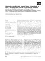
Buchholz relay
This relay is actuated by gas and oil inside the transformer bank. The turn-to-earth fault,
turn-to-turn fault or other internal fault inside the transformer will generate gases in
sufficient quantities to operate this protection device and actuate the operating of circuit
breaker. When a fault occurs inside the oil-filled transformer tank, the fault arc produces
gases, which create pressure inside the oil. In the conservator type of tank construction, the
pressure created in the oil is detected by a pressure vane in the pipe which connects the
transformer tank with the conservator. The movement of the vane is detected by a switch,
which can be used to sound an alarm or send the trip contact to the circuit breaker.
1
2
Figure 2.1 Buchholz Relay
11
Table 2.3 Buchholz Relay on Different Transformer Rating
Transformer rating (MVA)
Alarm volume of gas
Trip minimum oil
(cm3)
velocity (cm/s)
Pipe diameter (in)
up to 1 MVA
1
110
70 – 130
1-10
2
200
25 – 140
>10
3
250
90 - 160
Transformer conditions can cause an alarm signal:
•
hot spots in a core caused by short circuiting in laminations
•
breakdown on the insulation
•
winding faults causing low currents
•
leakage of oil
Buchholz relay has two signals in its operation i.e. alarm signal and trip signal.
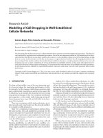
Temperature relay
Temperature relay works based on the temperature of the transformer. When the
temperature is high, then this relay will give the alarm signal. If the temperature is extremely
high, then this relay will send a trip command to the circuit breaker.
The temparature sensors are also commonly used to start and stop the cooling system of the
transformer.
3
2
1
1. Temperature Sensor
2. White Needle
(real time temperature)
3. Red Needle
(maximum temperature)
Figure 2.2 Temperature Relay
12
Sudden Pressure Relay
The sudden pressure relay operates based on the rate of rise of gas in the transformer. It can
be applied to any transformer with the sealed air or gas chamber above the oil level. It will
not operate on static pressure or pressure changes resulting from normal operation of the
transformer. This sudden pressure relay is usually found at the transformer with a gas
cushion at the top of the bank. Just the same with Buchholz relay, a pressure wave created
by a fault is detected by this relay.
Figure 2.3 Sudden Pressure Relay
There are two types of sudden pressure relay, membrane type and pressure relief valve
type. For membrane type, the membrane will break when the pressure is above its design.
For pressure relief valve type, the valve will open and remove the pressure with the oil when
the pressure inside the transformer exceeds the spring pressure. The valve is pressed by the
spring in the normal condition.
Faults on the bushings do not create an arc in the insulating oil and must be protected by
other protection system. The combination of the pressure relay (sudden pressure relay and
Buchholz relay) and differential relay provides an excellent protection system for a power
transformer.
13
2.4. Electrical Protection
There are many electrical protective relays that are installed to protect the transformer.
Figure 2.4 shows all of the electrical protection relays with their protection zone. The
transformer is also equipped with some control equipments i.e tap changer control and
metering as shown in figure 2.5
150 kV
OCR/GFR
50/51P/51GP
87N
87
SBEF
51NS
87N
OCR/GFR
50/51S/51G
70 kV
OCR/GF
Figure 2.4 Electrical Transformer Protection
14
Figure 2.5 Typical Wiring of Electrical Transformer Control and Protection System
Differential relay
Differential protection relies on the Kirchoff’s Current Law that states the sum of currents
entering a node equals the sum of currents leaving a node.
Applied to differential
protection, it means that the sum of currents entering a bus (transformer, transmission line,
busbar, or generator) equals the sum of those leaving. If the sum of these currents (for a
given circuit) is not zero, then it must be due to a short circuit caused either by an earth fault
or a phase-to-phase fault.
Differential relays take a variety of forms, depending on the equipment they protect. The
definition of such a relay is “one that operates when the vector difference of two or more
similar electrical quantities exceeds a predetermined amount” [32].
Differential relay is one of the protective relays of the transformer. It is accurate to detect
the internal fault of the transformer even when the primary and secondary currents are not
higher than the nominal current. But, it also has limitation when the turn-to-earth fault is
near the neutral end of the transformer. The normalized primary and secondary current
15
difference is not big enough to operate the relay. The same condition happen if there is
turn-to-turn fault when the faulty (short circuited) turns are small.
2
1
B
B
I2
I1
I2
I1
1
2
B
R IR=I1-I2= 0
(a) External Fault
B
R IR=I1+ I2≠ 0
(b) Internal Fault
Figure 2.6 Principle of Differential Relay Protection
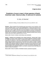
Figure 2.6 shows an explanatory diagram illustrating the principle of the differential relay
protection. Current transformers with similar characteristics and ratio are connected on the
both sides of the transformer and a relay is connected between the two current
transformers by using pilot wires. Under healthy or external fault conditions, the current
distribution as shown in figure 2.6 (a), no current flowing in the relay. When the internal
fault occurs as shown in figure 2.6 (b), the conditions of balance are upset and current flows
in the relay to cause operation. It can be noted also that the protected zone of this
differential relay is between the two current transformers. If the fault had occurred beyond,
as shown in figure 2.6 (a), than the operation will not occur as the fault current would then
flow through both current transformers thus maintaining the balance.
Transformer differential relay are subject to several factors that can cause maloperation
such as : different voltage level, including tap changer, which result in different currents in
the connecting circuits, ratio mismatch between current transformers , mismatch that occur
on the taps, phase-angle shift introduced by transformer wye(star)-delta connections, and
magnetizing inrush currents, which differential relay sees as internal faults.
Those above factors can be accommodated by the design of current transformer and
combination of relay with proper connection and applications. The connection of differential
relay, current transformers, interposing current transformer, and auxiliary current
transformers (ACT) is used to overcome the above factor for the older/electromechanical
differential relay protection. For the newer/numerical differential relay, the information of
16
the transformer and current transformer connection must be included correctly to the relay
setting without any auxiliary connections.
In general, the current transformers on the wye side must be connected in delta and the
current transformers on delta side connected in wye. These arrangements will compensate
the phase angle shift introduced by wye delta bank and blocks the zero sequence current
from the differential circuit on external ground faults. The zero sequence current will flow in
the differential circuit for external ground fault on the grounded wye side; if the current
transformer connected in wye, the relay would misoperate. With the current transformers
connected in delta, the zero sequence current circulates inside the current transformers,
preventing relay maloperation.
Transformer 150/70/16 kV, 100 MVA
Vector Group : YNyn0 (d11)
φR
φS
φT
SECONDARY
PRIMARY
CT
CT
IR
IR
IS
IS
IT
φS
IT
ir
is
it
ACT
Yd 11
i
Differential
Relay
i
i
i
i
i
φT
ACT
Dy 1
ir
is
it-
φR
ir
is
it
Figure 2.7 The design of current transformer and combination of relay
for 150/70/16 kV YYd transformer.
Auxiliary current transformers or relay taps ratios should be as close as possible to the
current ratios for a balanced maximum load condition. When there are more than two
winding, all combinations must be considered.
After current transformer ratios and auxiliary current transformer taps have been selected,
the continuous rating of relay should be checked for the compatibility of transformer load.
17
If the relay current exceeds its continuous rating, a higher current transformer ratio or
auxiliary current transformer may be required.
The percentage of current mismatch should be checked to ensure the auxiliary current
transformer selected have adequate safety margin.
Percentage mismatch can be
determined as:
I L TL
−
I H TH
M =
× 100%
S
(2.1)
Where IL and IH are the relay input currents for low and voltage side, TL and TH are the relay
tap setting for low and high voltage side and S is the smaller between those two terms (IL/IH)
or (TL/TH).
The current in the differential relay will not exactly zero at the normal operating condition or
when external fault occur. It is normal because the tap of the transformer, the current
transformer (CT) error, mismatch, and the excitation current.
The minimum pick current of the differential relay is generally quite safe at 30% of the
nominal current. It already accommodated the maximum 10% tap error, 10% CT error, 4 %
mismatch, 1% excitation current, and 5% safety margin.
Number of turn
Preliminary tap
Terminal
1-2
2-3
3-4
4-5
5-6
Transformer rating
5/5 A 5/1 A 1/1 A
1
1
1
1
25
1
1
1
1
25
5
5
5
5
125
Number of turn
Preliminary tap
Terminal
X- 7
7-8
8-9
S1 - S2
S3 - S4
Transformer rating
5/5 A 5/1 A 1/1 A
5
5
5
25
18
5
5
9
125
90
25
25
25
125
90
18
Figure 2.8 Auxiliary Current Transformer
There two types of differential relays, non-bias and bias differential relay protection. The
non-bias relay only considers the differential current as a trigger to operate the relay and the
bias relay considers not only differential current but also bias current to operate the relay.
I diff
(Differential current)
I1 - I2
Operate
Restrain
(I1 - I2)/2
I bias
(Mean through current)
Figure 2.9 Non-Bias Differential Relay
19
I diff
(Differential current)
I1 - I2
Operate
Restrain
(I1 - I2)/2
I bias
(Mean through current)
Figure 2.10 Bias Differential Relay
Operating current =
smallest current in operating coil to cause operation
× 100% (2.2)
rated current of the operating coil
% minimum pick up current = 10 – 30% nominal current
Slope =
current in operating coil to cause operation
×100%
current in restraining
% slope =
(2.3)
I1 - I 2
× 100%
(I1 + I 2 )/2
The bias current is a function of the through fault current and stabilizes the relay against
heavy through faults.
Under through-fault conditions, when operation is not required, no current should flow on
the relay but because of imperfect matching of the current transformers and the effect due
to tap changing, some spill current may exceed the minimum pick up current and flow in the
relay. This, however, will not cause any operation of the relay unless the ratio of differential
current to mean through fault current is exceeded and the restraint or bias which is
increases as the through fault current increases, thus enabling sensitive settings to be
obtained with high degree of stability.
Over Current Relay (OCR) and Ground Fault Relay (GFR)
Over current relay is classified as back up protection of the transformer because it is not
sensitive enough to detect the internal fault. It is installed at the source side and also the
load side of the transformer. It will work if the current is over the setting of the relay.
20
To allow transformer overloading when necessary, the pick up value of the over current
relays must be set up above the nominal current. The definite minimum operating time at
currents above a certain level or pick up current setting is an essential feature to obtain
adequate discriminating time margins. To obtain flexibility, tappings are provided on the
main input winding with a current value or percentage being assigned. The pick up current in
Java Bali system is set 1.2 times nominal current of the transformer with inverse
characteristics.
Fast operation is not possible, since the transformer relays must coordinate with all other
relays they overreach. Some times it also has definite time characteristics with
instantaneous trip command when the current is around 8-10 times of the nominal current.
This setting must be above the inrush current. Often, instantaneous trip units cannot be
used because the fault currents are too small.
Table 2.3 Over Current Relay (OCR) Setting
No
Description
Primary (150 kV)
Secondary (70 kV)
1
Relay Type
Non Directional Over
Non Directional Over
Current Relay
Current Relay
2
Characteristic
Standard Inverse
Standard Inverse
3
Current Setting
1.2 x transformer nominal
1.2 x transformer
current
nominal current
∆t = 0.3-0.5 second from
∆t = 0.3-0.5 second from
tripping time of the bus 70
tripping time of the
kV
feeder or line
( recommendation : 0.5
( recommendation : 0.5
second )
second )
transformer nominal
0.5 x transformer
current x (1/Z(pu))
nominal current x
4
5
Time Setting
Instantaneous Trip
(1/Z(pu))
GFR is in the same unit with the OCR but the input comes from the neutral current
transformer. The setting of the ground fault relay are :
Table 2.4 Ground Fault Relay Setting
No
Description
Primary (150 kV)
Secondary (70 kV)
Neutral Transformer
1
Relay Type
Non Directional
Non Directional
Stanby Earth Fault
Ground Fault
Ground Fault Relay
Relay
Relay
21
2
Characteristic
Standard Inverse
Definite Time
Definite Time
3
Current Setting
0.2 x transformer
(0.2 – 0.4) x nominal
NGR maximum
nominal current
current of Neutral
continuous current
Grounding Resistor
(NGR)
4
Time Setting
∆t = 0.3-0.5
∆t = 0.3-0.5 second
0.5 x NGR thermal
second from
from tripping time of
strength time
tripping time of
the feeder or line
the bus 70 kV
(recommendation :
(recommendation : 0.5 second )
0.5 second )
5
Instantaneous Trip
Not activated
Not activated
Not activated
Restricted Earth Fault (REF) relay
REF relay use the same mechanism of differential relay. It works when the current flow
through the relay is over the setting of the relay. The only difference is that REF relay has
inputs from the current transformer of the grounding and neutral. When there’s turn to
ground fault then the fault current will flow through the grounding and compared to the
neutral current and will be detected by this relay.
Figure 2.11 External Fault Current Distribution in REF Relay
22
From figure 2.11 above, it could be seen that there is no current flow at the REF relay when
external fault occurs. On the other hand, the REF relay will operate when the earth fault
happen in the internal protected zone in figure 2.12.
Figure 2.12 Internal Fault Current Distribution in REF Relay
23
III. TRANSFORMER MODELING ON ATPDraw
3.1. Introduction
The transformer which is modeled in this thesis is 150/70/16 kV three-phase three-winding
YYd transformer. The transformer is already installed at Wlingi Substation. It is
manufactured by PT Pauwels Trafo Asia, a subsidiary company of Pauwels that produce
transformer and other primary equipment in Indonesia. The detail transformer design and
factory test result can be shown on the appendix.
3.2. BCTRAN Modeling
The transformer model could be built by using a lot of components, i.e BCTRAN, saturated
transformer, coupled inductance, etc. BCTRAN is used in this model because of the available
data of the transformer.
The inputs of BCTRAN consist of MVA, voltage, winding connection, grounding, impedance,
losses, frequency, short circuit and open circuit test, etc. They can be easily taken from the
name plate and the factory test of the transformer. This name plate and factory test of the
transformer is prepared by the transformer manufactures when the customer (electrical
utility, industry, etc) buy it. So it is easy to get this data because all transformers are
accompanied by this data. BCTRAN can make a model of any kind of transformer, two and
three winding, single and three phases, wye and delta winding, and autotransformer.
BCTRAN generates the impedance matrix (R and L matrix) of the transformer.
Parameters of the transformer are obtained from the transformer name plate. Number of
phase, number of winding, frequency, rated power, line to line voltage, winding connection,
and phase shift can be included easily without any modification. There’s a special case for
the type of transformer core.
Under the open circuit tab, the user can specify how the real factory test has been
performed and where to connect the excitation branch. In case of a three winding
transformer, HV, LV, and the TV winding could be chosen. Normally the lowest voltage is
preferred, but stability problems for delta-connected nonlinear inductances could require
24
the lowest Y-connected winding to be used [2]. Up to 6 points on the magnetizing curve can
be specified. The excitation voltage and current must be specified in % and the losses in kW.
With reference to the ATP Rule Book[1], the values at 100 % voltage is used directly as
IEXPOS=Curr (%) and LEXPOS=Loss (kW). One exception is if External Lm is chosen under
positive core magnetization. In this case only, the resistive current is specified resulting in
IEXPOS=Loss/(10 * SPOS), where SPOS is the Power (MVA) value specified under Ratings of
the winding where the test has been performed. If zero sequence open circuit test data are
also available, the user can similarly specify them to the right. The values for other voltages
than 100 % can be used to define a nonlinear magnetizing inductance/resistance.
This is set under positive core magnetization:
•
Specifying Linear internal will result in a linear core representation based on the 100
% voltage values.
•
Specifying External Lm//Rm the magnetizing branch will be omitted in the BCTRAN
calculation and the program assumes that the user will add these components as
external objects to the model.
•
Specifying External Lm will result in calculation of a nonlinear magnetizing
inductance first as an Irms-Urms characteristic, then automatically transformed to a
current-fluxlinked characteristic (by means of an internal SATURA-like routine). The
current in the magnetizing inductance is calculated as
I RMS [A] =
(10 ⋅ Curr [%] ⋅ SPOS [MVA] / 3)2 − ( Loss[kW ] / 3) 2 / Vref [kV ]
(3.1)
where Vref is actual rated voltage specified under Ratings, divided by 3 for Y- and Autoconnected transformers.
The user can choose to Auto-add nonlinearities under Structure and in this case the
magnetizing inductance is automatically added to the final ATP-file as a Type-98
inductance[1]. ATPDraw connects the inductances in Y or D dependent on the selected
connection for actual winding for a 3-phase transformer. In this case, the user has no control
on the initial state of the inductor(s). If more control is needed (for instance to calculate the
fluxlinked or set initial conditions) Auto-add nonlinearities should not be checked. The user
is free to create separate nonlinear inductances, however. The Copy+ button at the bottom
of the dialog box allows the user to copy the calculated nonlinear characteristic to an
external nonlinearity. What to copy is selected under View/Copy. To copy the fluxlinkedcurrent characteristic used in Type-93 and Type-98 inductances Lm-flux should be selected.
25