Data Types
Bạn đang xem bản rút gọn của tài liệu. Xem và tải ngay bản đầy đủ của tài liệu tại đây (162.89 KB, 36 trang )
CHAPTER
4
Data Types
In this chapter, we examine the object types used in
VHDL. The types allowed in VHDL consist of everything
from scalar numeric types to composite arrays and
records to file types. The first step in looking at the var-
ied VHDL types is to review the VHDL objects that can
attain the varied types. Then we use examples to show
how many types of descriptions can be made easier to
read by using the power of enumerated and composite
data types.
4
Chapter Four
74
Object Types
A VHDL object consists of one of the following:
■ Signal, which represents interconnection wires that connect com-
ponent instantiation ports together.
■ Variable, which is used for local storage of temporary data, visible
only inside a process.
■ Constant, which names specific values.
Signal
Signal objects are used to connect entities together to form models. Signals
are the means for communication of dynamic data between entities. A
signal declaration looks like this:
SIGNAL signal_name : signal_type [:= initial_value];
The keyword
SIGNAL
is followed by one or more signal names. Each
signal name creates a new signal. Separating the signal names from the
signal type is a colon. The signal type specifies the data type of the infor-
mation that the signal contains. Finally, the signal can contain an initial
value specifier so that the signal value may be initialized.
Signals can be declared in entity declaration sections, architecture
declarations, and package declarations. Signals in package declarations
are also referred to as global signals because they can be shared among
entities.
Following is an example of signal declarations:
LIBRARY IEEE;
USE IEEE.std_logic_1164.ALL;
PACKAGE sigdecl IS
TYPE bus_type IS ARRAY(0 to 7) OF std_logic;
SIGNAL vcc : std_logic := ‘1’;
SIGNAL ground : std_logic := ‘0’;
FUNCTION magic_function( a : IN bus_type) RETURN
bus_type;
END sigdecl;
USE WORK.sigdecl.ALL;
LIBRARY IEEE;
75
Data Types
USE IEEE.std_logic_1164.ALL;
ENTITY board_design is
PORT( data_in : IN bus_type;
PORT( data_out : OUT bus_type);
SIGNAL sys_clk : std_logic := ‘1’;
END board_design;
ARCHITECTURE data_flow OF board_design IS
SIGNAL int_bus : bus_type;
CONSTANT disconnect_value : bus_type
:= (‘X’, ‘X’, ‘X’, ‘X’, ‘X’, ‘X’, ‘X’, ‘X’);
BEGIN
int_bus <= data_in WHEN sys_clk = ‘1’
ELSE int_bus;
data_out <= magic_function(int_bus) WHEN sys_clk = ‘0’
ELSE disconnect_value;
sys_clk <= NOT(sys_clk) after 50 ns;
END data_flow;
Signals
vcc
and
ground
are declared in package
sigdecl
. Because
these signals are declared in a package, they can be referenced by more
than one entity and are therefore global signals. For an entity to refer-
ence these signals, the entity needs to use package
sigdecl
. To use the
package requires a VHDL
USE
clause, as shown here:
USE work.sigdecl.vcc;
USE work.sigdecl.ground;
Or:
USE work.sigdecl.ALL;
In the first example, the objects are included in the entity by specific
reference. In the second example, the entire package is included in the en-
tity. In the second example, problems may arise because more than what
is absolutely necessary is included. If more than one object of the same
name results because of the
USE
clause, none of the objects is visible, and a
compile operation that references the object fails.
SIGNALS GLOBAL TO ENTITIES Inside the entity declaration
section for entity
board_design
is a signal called
sys_clk
. This signal can
be referenced in entity
board_design
and any architecture for entity
board_design
. In this example, there is only one architecture,
data_flow
,
Chapter Four
76
for
board_design
. The signal
sys_clk
can therefore be assigned to and
read from in entity
board_design
and architecture
data_flow
.
ARCHITECTURE LOCAL SIGNALS Inside of architecture
data_flow
is a signal declaration for signal
int_bus
. Signal
int_bus
is of
type
bus_type
, a type defined in package
sigdecl
. The
sigdecl
package is
used in entity
board
; therefore, the type
bus_type
is available in architec-
ture
data_flow
. Because the signal is declared in the architecture decla-
ration section, the signal can only be referenced in architecture
data_flow
or in any process statements in the architecture.
Variables
Variables are used for local storage in process statements and subprograms.
(Subprograms are discussed in Chapter 6, “Predefined Attributes.”) As
opposed to signals, which have their values scheduled in the future, all
assignments to variables occur immediately. A variable declaration looks
like this:
VARIABLE variable_name {,variable_name} : variable_type[:=
value];
The keyword
VARIABLE
is followed by one or more variable names. Each
name creates a new variable. The construct
variable_type
defines the
data type of the variable, and an optional initial value can be specified.
Variables can be declared in the process declaration and subprogram
declaration sections only. An example using two variables is shown here:
LIBRARY IEEE;
USE IEEE.std_logic_1164.ALL;
ENTITY and5 IS
PORT ( a, b, c, d, e : IN std_logic;
PORT ( q : OUT std_logic);
END and5;
ARCHITECTURE and5 OF and5 IS
BEGIN
PROCESS(a, b, c, d, e)
VARIABLE state : std_logic;
VARIABLE delay : time;
BEGIN
state := a AND b AND c AND d AND e;
IF state = ‘1’ THEN
77
Data Types
delay := 4.5 ns;
ELSIF state = ‘0’ THEN
delay := 3 ns;
ELSE
delay := 4 ns;
END IF;
q <= state AFTER delay;
END PROCESS;
END and5;
This example is the architecture for a five-input
AND
gate. There are two
variable declarations in the process declaration section: one for variable
state
and one for variable
delay
. Variable
state
is used as a tempo-
rary storage area to hold the value of the
AND
function of the inputs. Tem-
porary-storage value
delay
is used to hold the delay value that will be
used when scheduling the output value. Both of these values cannot be sta-
tic data because their values depend on the values of inputs
a
,
b
,
c
,
d
, and
e
. Signals could have been used to store the data, but there are several rea-
sons why a signal was not used:
■ Variables are inherently more efficient because assignments hap-
pen immediately, while signals must be scheduled to occur.
■ Variables take less memory, while signals need more information
to allow for scheduling and signal attributes.
■ Using a signal would have required a
WAIT
statement to synchronize
the signal assignment to the same execution iteration as the usage.
When any of the input signals
a
,
b
,
c
,
d
, or
e
change, the process is in-
voked. Variable
state
is assigned the
AND
of all of the inputs. Next, based
on the value of variable
state
, variable
delay
is assigned a delay value.
Based on the delay value assigned to variable
delay
, output signal
q
will
have the value of variable
state
assigned to it.
Constants
Constant objects are names assigned to specific values of a type. Constants
give the designer the ability to have a better-documented model, and a
model that is easy to update. For instance, if a model requires a fixed
value in a number of instances, a constant should be used. By using a
constant, the designer can change the value of the constant and recompile,
Chapter Four
78
and all of the instances of the constant value are updated to reflect the
new value of the constant.
A constant also provides a better-documented model by providing more
meaning to the value being described. For instance, instead of using the
value 3.1414 directly in the model, the designer should create a constant
as in the following:
CONSTANT PI: REAL := 3.1414;
Even though the value is not going to change, the model becomes more
readable.
A constant declaration looks like this:
CONSTANT constant_name {,constant_name} : type_name[:=
value];
The
value
specification is optional, because VHDL also supports deferred
constants. These are constants declared in a package declaration whose
value is specified in a package body.
A constant has the same scoping rules as signals. A constant declared
in a package can be global if the package is used by a number of entities. A
constant in an entity declaration section can be referenced by any archi-
tecture of that entity. A constant in an architecture can be used by any
statement inside the architecture, including a process statement. A constant
declared in a process declaration can be used only in a process.
Data Types
All of the objects we have been discussing until now
—
the signal, the
variable, and the constant
—
can be declared using a type specification to
specify the characteristics of the object. VHDL contains a wide range of
types that can be used to create simple or complex objects.
To define a new type, you must create a type declaration. A type dec-
laration defines the name of the type and the range of the type. Type
declarations are allowed in package declaration sections, entity declara-
tion sections, architecture declaration sections, subprogram declaration
sections, and process declaration sections.
A type declaration looks like this:
TYPE type_name IS type_mark;
79
Data Types
Enumerated
Real
Integer
Physical
Scalar
Array
Record
Composite
Access
File
Types
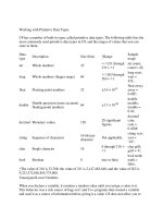
Figure 4-1
VHDL Data Types
Diagram.
A
type_mark
construct encompasses a wide range of methods for spec-
ifying a type. It can be anything from an enumeration of all of the values
of a type to a complex record structure. In the next few sections, type
marks are examined. All of the scoping rules that were defined for signals
and variables apply to type declarations also.
Figure 4-1 is a diagram showing the types available in VHDL. The four
broad categories are scalar types, composite types, access types, and file
types. Scalar types include all of the simple types such as integer and real.
Composite types include arrays and records. Access types are the equiv-
alent of pointers in typical programming languages. Finally, file types give
the designer the ability to declare file objects with designer-defined file
types.
Scalar Types
Scalar types describe objects that can hold, at most, one value at a time.
The type itself can contain multiple values, but an object that is declared
Chapter Four
80
to be a scalar type can hold, at most, one of the scalar values at any point
in time. Referencing the name of the object references the entire object.
Scalar types encompass these four classes of types:
■ Integer types
■ Real types
■ Enumerated types
■ Physical types
INTEGER TYPES are exactly like mathematical integers. All of the nor-
mal predefined mathematical functions like add, subtract, multiply, and di-
vide apply to integer types. The VHDL LRM does not specify a maximum
range for integers, but does specify the minimum range: from -2,147,483,647
to 12,147,483,647. The minimum range is specified by the Standard
package contained in the Standard Library.
The Standard package defines all of the predefined VHDL types pro-
vided with the language. The Standard Library is used to hold any packages
or entities provided as standard with the language.
It may seem strange to some designers who are familiar with two’s
complement representations that the integer range is specified from
Ϫ2,147,483,647 to ϩ2,147,483,647 when two’s complement integer repre-
sentations usually allow one smaller negative number, Ϫ2,147,483,648. The
language defines the integer range to be symmetric around 0.
Following are some examples of integer values:
ARCHITECTURE test OF test IS
BEGIN
PROCESS(X)
VARIABLE a : INTEGER;
VARIABLE b : int_type;
BEGIN
a := 1; --Ok 1
a := -1; --Ok 2
a := 1.0; --error 3
END PROCESS;
END test;
The first two statements (1 and 2) show examples of a positive integer
assignment and a negative integer assignment. Line 3 shows a non-
integer assignment to an integer variable. This line causes the compiler
to issue an error message. Any numeric value with a decimal point is con-
sidered a real number value. Because VHDL is a strongly typed language,
81
Data Types
for the assignment to take place, either the base types must match or a
type-casting operation must be performed.
REAL TYPES Real types are used to declare objects that emulate
mathematical real numbers. They can be used to represent numbers out
of the range of integer values as well as fractional values. The minimum
range of real numbers is also specified by the Standard package in the
Standard Library, and is from Ϫ1.0Eϩ38 to ϩ1.0Eϩ38. These numbers
are represented by the following notation:
ϩ
or -number.number[E
ϩ
or -number]
Following are a few examples of some real numbers:
ARCHITECTURE test OF test IS
SIGNAL a : REAL;
BEGIN
a <= 1.0; --Ok 1
a <= 1; --error 2
a <= -1.0E10; --Ok 3
a <= 1.5E-20; --Ok 4
a <= 5.3 ns; --error 5
END test;
Line 1 shows how to assign a real number to a signal of type
REAL
. All
real numbers have a decimal point to distinguish them from integer values.
Line 2 is an example of an assignment that does not work. Signal
a
is of
type
REAL
, and a real value must be assigned to signal
a
. The value 1 is
of type
INTEGER
, so a type mismatch is generated by this line.
Line 3 shows a very large negative number. The numeric characters to
the left of the character
E
represent the mantissa of the real number,
while the numeric value to the right represents the exponent.
Line 4 shows how to create a very small number. In this example, the
exponent is negative so the number is very small.
Line 5 shows how a type
TIME
cannot be assigned to a real signal. Even
though the numeric part of the value looks like a real number, because of
the units after the value, the value is considered to be of type
TIME
.
ENUMERATED TYPES An enumerated type is a very powerful tool
for abstract modeling. A designer can use an enumerated type to repre-
sent exactly the values required for a specific operation. All of the values
of an enumerated type are user-defined. These values can be identifiers
or single-character literals. An identifier is like a name. Examples are x,
abc, and black. Character literals are single characters enclosed in quotes,
such as
‘X’
,
‘1’
, and
‘0’
.
Chapter Four
82
A typical enumerated type for a four-state simulation value system looks
like this:
TYPE fourval IS ( ‘X’, ‘0’, ‘1’, ‘Z’ );
This type contains four character literal values that each represent
a unique state in the four-state value system. The values represent the
following conditions:
■
‘X’
—
An unknown value
■
‘0’
—
A logical 0 or false value
■
‘1’
—
A logical 1 or true value
■
‘Z’
—
A tristate or open collector value
Character literals are needed for values
‘1’
and
‘0’
to separate these
values from the integer values 1 and 0. It would be an error to use the val-
ues 1 and 0 in an enumerated type, because these are integer values. The
characters
X
and
Z
do not need quotes around them because they do not
represent any other type, but the quotes were used for uniformity.
Another example of an enumerated type is shown here:
TYPE color IS ( red, yellow, blue, green, orange );
In this example, the type values are very abstract
—
that is, not repre-
senting physical values that a signal might attain. The type values in type
color
are also all identifiers. Each identifier represents a unique value of
the type; therefore, all identifiers of the type must be unique.
Each identifier in the type has a specific position in the type, determined
by the order in which the identifier appears in the type. The first identifier
has a position number of 0, the next a position number of 1, and so on.
(Chapter 5, “Subprograms and Packages” includes some examples using
position numbers of a type.)
A typical use for an enumerated type would be representing all of the
instructions for a microprocessor as an enumerated type. For instance, an
enumerated type for a very simple microprocessor could look like this:
TYPE instruction IS ( add, sub, lda, ldb, sta, stb, outa,
xfr );
The model that uses this type might look like this:
PACKAGE instr IS
TYPE instruction IS ( add, sub, lda, ldb, sta, stb,
outa, xfr );
83
Data Types
END instr;
USE WORK.instr.ALL;
ENTITY mp IS
PORT (instr : IN instruction;
PORT (addr : IN INTEGER;
PORT (data : INOUT INTEGER);
END mp;
ARCHITECTURE mp OF mp IS
BEGIN
PROCESS(instr)
TYPE regtype IS ARRAY(0 TO 255) OF INTEGER;
VARIABLE a, b : INTEGER;
VARIABLE reg : regtype;
BEGIN
--select instruction to
CASE instr is --execute
WHEN lda =>
a := data; --load a accumulator
WHEN ldb =>
b := data; --load b accumulator
WHEN add =>
a := a 1 b; --add accumulators
WHEN sub =>
a := a -b; --subtract accumulators
WHEN sta =>
reg(addr) := a; --put a accum in reg array
WHEN stb =>
reg(addr) := b; --put b accum in reg array
WHEN outa =>
data <= a; --output a accum
WHEN xfr => --transfer b to a
a := b;
END CASE;
END PROCESS;
END mp;
The model receives an instruction stream (
instr
), an address stream
(
addr
), and a data stream (
data
). Based on the value of the enumerated
value of
instr
, the appropriate instruction is executed. A
CASE
statement
is used to select the instruction to execute. The statement is executed and
the process then waits for the next instruction.
Another common example using enumerated types is a state machine.
State machines are commonly used in designing the control logic for ASIC
Chapter Four
84
or FPGA devices. They represent a very easy and understandable method
for specifying a sequence of actions over time, based on input signal values.
ENTITY traffic_light IS
PORT(sensor : IN std_logic;
PORT(clock : IN std_logic;
PORT(red_light : OUT std_logic;
PORT(green_light : OUT std_logic;
PORT(yellow_light : OUT std_logic);
END traffic_light;
ARCHITECTURE simple OF traffic_light IS
TYPE t_state is (red, green, yellow);
Signal present_state, next_state : t_state;
BEGIN
PROCESS(present_state, sensor)
BEGIN
CASE present_state IS
WHEN green =>
next_state <= yellow;
red_light <= ‘0’;
green_light <= ‘1’;
yellow_light <= ‘0’;
WHEN red =>
red_light <= ‘1’;
green_light <= ‘0’;
yellow_light <= ‘0’;
IF (sensor = ‘1’) THEN
next_state <= green;
ELSE
next_state <= red;
END IF;
WHEN yellow =>
red_light <= ‘0’;
green_light <= ‘0’;
yellow_light <= ‘1’;
next_state <= red;
END CASE;
END PROCESS;
PROCESS
BEGIN
WAIT UNTIL clock’EVENT and clock = ‘1’;
present_state <= next_state;
END PROCESS;
END simple;
The state machine is described by two processes: the first calculates the
next state logic, and the second latches the next state into the current
state. Notice how the enumerated type makes the model much more
readable because the state names represent the color of the light that is
currently being displayed.
85
Data Types
PHYSICAL TYPES Physical types are used to represent physical
quantities such as distance, current, time, and so on. A physical type pro-
vides for a base unit, and successive units are then defined in terms of this
unit. The smallest unit representable is one base unit; the largest is deter-
mined by the range specified in the physical type declaration. An example
of a physical type for the physical quantity current is shown here:
TYPE current IS RANGE 0 to 1000000000
UNITS
na; --nano amps
ua = 1000 na; --micro amps
ma = 1000 ua; --milli amps
a = 1000 ma; --amps
END UNITS;
The type definition begins with a statement that declares the name of the
type (
current
) and the range of the type (0 to 1,000,000,000). The first unit
declared in the
UNITS
section is the base unit. In the preceding example,
the base unit is
na
. After the base unit is defined, other units can be defined
in terms of the base unit or other units already defined. In the preceding
example, the unit
ua
is defined in terms of the base unit as 1000 base
units. The next unit declaration is
ma
. This unit is declared as 1000
ua
.
The units declaration section is terminated by the
END UNITS
clause.
More than one unit can be declared in terms of the base unit. In the pre-
ceding example, the
ma
unit can be declared as 1000
ma
or 1,000,000
na
. The
range constraint limits the minimum and maximum values that the phys-
ical type can represent in base units. The unit identifiers all must be unique
within a single type. It is illegal to have two identifiers with the same name.
PREDEFINED PHYSICAL TYPES
The only predefined physical type in VHDL is the physical type
TIME
. This
type is shown here:
TYPE TIME IS RANGE <implementation defined>
UNITS
fs; --femtosecond
ps = 1000 fs; --picosecond
ns = 1000 ps; --nanosecond
us = 1000 ns; --microsecond
ms = 1000 us; --millisecond
sec = 1000 ms; --second
min = 60 sec; --minute
hr = 60 min; --hour
END UNITS;
Chapter Four
86
The range of time is implementation-defined but has to be at least the
range of integer, in base units. This type is defined in the Standard package.
Following is an example using a physical type:
PACKAGE example IS
TYPE current IS RANGE 0 TO 1000000000
UNITS
na; --nano amps
ua = 1000 na; --micro amps
ma = 1000 ua; --milli amps
a = 1000 ma; --amps
END UNITS;
TYPE load_factor IS (small, med, big );
END example;
USE WORK.example.ALL;
ENTITY delay_calc IS
PORT ( out_current : OUT current;
PORT ( load : IN load_factor;
PORT ( delay : OUT time);
END delay_calc;
ARCHITECTURE delay_calc OF delay_calc IS
BEGIN
delay <= 10 ns WHEN (load = small) ELSE
delay <= 20 ns WHEN (load = med) ELSE
delay <= 30 ns WHEN (load = big) ELSE
delay <= 10 ns;
out_current <= 100 ua WHEN (load = small)ELSE
out_current <= 1 ma WHEN (load = med) ELSE
out_current <= 10 ma WHEN (load = big) ELSE
out_current <= 100 ua;
END delay_calc;
In this example, two examples of physical types are represented. The
first is of predefined physical type
TIME
and the second of user-specified
physical type
current
. This example returns the current output and delay
value for a device based on the output load factor.
Composite Types
Looking back at the VHDL types diagram in Figure 4-1, we see that
composite types consist of array and record types. Array types are groups
of elements of the same type, while record types allow the grouping of