Atmel AVR Operating Parameters and Interfacing
Bạn đang xem bản rút gọn của tài liệu. Xem và tải ngay bản đầy đủ của tài liệu tại đây (565.44 KB, 54 trang )
105
CHAPTER 6
Atmel AVR Operating Parameters
and Interfacing
Objectives: After reading this chapter, the reader should be able to
•
describe the voltage and current parameters for the Atmel AVR HC CMOS-type
microcontroller,
•
apply the voltage and current parameters toward properly interfacing I/O devices to the
Atmel AVR microcontroller,
•
interface a wide variety of I/O devices to the Atmel AVR microcontroller,
•
describe the special concerns that must be followed when the Atmel AVR microcontroller
is used to interface to a high-power DC or AC device,
•
discuss the requirement for an optical-based interface,
•
describe how to control the speed and direction of a DC motor, and
•
describe how to control several types of AC loads.
OurfirsttextbookforM&C,Microcontrollers Fundamentals for Engineers and Scientists,
contained a chapter entitled ‘‘Operating Parameters and Interfacing’’ [1]. With M&C’s permission,
we have repeated this chapter here for your convenience. However, we have personalized the
information provided to the Atmel AVR line of microcontrollers. We have also expanded the
coverage of the chapter to include interface techniques for a number of additional I/O devices.
In this chapter, we introduce you to the extremely important concepts of the operating
envelope for a microcontroller. We begin by reviewing the voltage and current electrical parameters
for the HC CMOS-based Atmel AVR line of microcontrollers. We then show how to apply
this information to properly interface I/O devices to the ATmega16 microcontroller. We then
discuss the special considerations for controlling a high-power DC or AC load such as a motor
and introduce the concept of an optical interface. Throughout the chapter, we provide a number of
detailed examples.
106 ATMEL AVR MICROCONTROLLER PRIMER: PROGRAMMING AND INTERFACING
6.1 OPERATING PARAMETERS
The microcontroller is an electronic device that has precisely defined operating conditions. As long
as the microcontroller is used within its defined operating parameter limits, it should continue to
operate correctly. However, if the allowable conditions are violated, spurious results may result.
Any time a device is connected to a microcontroller, careful interface analysis must be
performed. Most microcontrollers are members of the ‘‘HC,’’ or high-speed CMOS family of
chips. As long as all components in a system are also of the ‘‘HC’’ family, as is the case for the
Atmel AVR line of microcontrollers, electrical interface issues are minimal. If the microcontroller is
connected to some component not in the HC family, electrical interface analysis must be completed.
Manufacturers readily provide the electrical characteristic data necessary to complete this analysis
in their support documentation.
To perform the interface analysis, there are eight different electrical specifications required
for electrical interface analysis. The electrical parameters are
•
V
OH
: the lowest guaranteed output voltage for a logic high,
•
V
OH
: the highest guaranteed output voltage for a logic low,
•
I
OH
: the output current for a V
OH
logic high,
•
I
OH
: the output current for a V
OH
logic low,
•
V
IH
: the lowest input voltage guaranteed to be recognized as a logic high,
•
V
IL
: the highest input voltage guaranteed to be recognized as a logic low,
•
I
IH
: the input current for a V
IH
logic high, and
•
I
IL
: the input current for a V
IL
logic low.
These electrical characteristics are required for both the microcontroller and the external
components. Typical values for a microcontroller in the HC CMOS family assuming V
DD
=
5.0
VandV
SS
=
0 V are provided below. The minus sign on several of the currents indicates a current
flow out of the device. A positive current indicates current flow into the device.
•
V
OH
=
4.2 V
,
•
V
OL
=
0.4 V
,
•
I
OH
= −
0.8 mA
,
•
I
OL
=
1.6 mA
,
•
V
IH
=
3.5 V
,
•
V
IL
=
1.0 V
,
•
I
IH
=
10
µ
A, and
•
I
IL
= −
10
µ
A.
It is important to realize that these are static values taken under very specific operating
conditions. If external circuitry is connected such that the microcontroller acts as a current source
ATMEL AVR OPERATING PARAMETERS AND INTERFACING 107
(current leaving microcontroller) or current sink (current entering microcontroller), the voltage
parameters listed above will also be affected.
In the current source case, an output voltage V
OH
is provided at the output pin of the
microcontroller when the load connected to this pin draws a current of I
OH
. If a load draws more
current from the output pin than the I
OH
specification, the value of V
OH
is reduced. If the load
current becomes too high, the value of V
OH
falls below the value of V
IH
for the subsequent logic
circuit stage and not be recognized as an acceptable logic high signal. When this situation occurs,
erratic and unpredictable circuit behavior results.
In the sink case, an output voltage V
OL
is provided at the output pin of the microcontroller
when the load connected to this pin delivers a current of I
OL
to this logic pin. If a load delivers
more current to the output pin of the microcontroller than the I
OL
specification, the value of V
OL
increases. If the load current becomes too high, the value of V
OL
rises above the value of V
IL
for the
subsequent logic circuit stage and not be recognized as an acceptable logic low signal. As before,
when this situation occurs, erratic and unpredictable circuit behavior results.
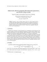
For convenience, this information is illustrated in Figure 6.1.InFigure6.1(a), we have
provided an illustration of the direction of current flow from the HC device and a comparison
of voltage levels. As a reminder, current flowing out of a device is considered a negative current
(source case), whereas current flowing into the device is considered positive current (sink case).
The magnitude of the voltage and current for HC CMOS devices are shown in Figure 6.1(b).
As more current is sunk or sourced from a microcontroller pin, the voltage will be pulled up or
pulled down, respectively, as shown in Figure 6.1(c). If I/O devices are improperly interfaced to the
microcontroller, these loading conditions may become excessive, and voltages will not be properly
interpreted as the correct logic levels.
You must also ensure that total current limits for an entire microcontroller port and overall
bulk port specifications are complied with. For planning purposes, the sum of current sourced or
sunk from a port should not exceed 100 mA. Furthermore, the sum of currents for all ports should
not exceed 200 mA. As before, if these guidelines are not complied with, erratic microcontroller
behavior may result.
The procedures presented in the following sections when followed carefully will ensure the
microcontroller will operate within its designed envelope. The remainder of the chapter is divided
into input device interface analysis followed by output device interface analysis.
6.2 INPUT DEVICES
In this section, we discuss how to properly interface input devices to a microcontroller. We will
start with the most basic input component, a simple on/off switch.
108 ATMEL AVR MICROCONTROLLER PRIMER: PROGRAMMING AND INTERFACING
V
DD
= 5 VDC
V
OH
V
OL
V
SS
= 0 VDC
Output Gate
Parameters
V
DD
= 5 VDC
V
IH
V
IL
V
SS
= 0 VDC
Input Gate
Parameters
I
OH
I
OL
I
IH
I
IL
a) Voltage and current electrical parameters
Output Parameters Input Parameters
V
OH
= 4.2 V
V
OL
= 0.4 V
I
OH
= - 0.8 mA
I
OL
= 1.6 mA
V
IH
= 3.5 V
V
IL
= 1.0 V
I
IH = 10 µA
I
IL = - 10 µA
b) HC CMOS voltage and current parameters
0
5
Current sink
Vout [V]
25
0
Iout [mA]
0
5
Current source
Vout [V]
-25
0
Iout [mA]
c) CMOS loading curves
FIGURE 6.1: Electrical voltage and current parameters: (a) voltage and current electrical parameters,
(b) HC CMOS voltage and current parameters, and (c) CMOS loading curves.
ATMEL AVR OPERATING PARAMETERS AND INTERFACING 109
6.2.1 Switches
Switches come in a variety of types. As a system designer, it is up to you to choose the appropriate
switch for a specific application. Switch varieties commonly used in microcontroller applications
are illustrated in Figure 6.2(a). Here is a brief summary of the different types:
•
Slide switch: A slide switch has two different positions: on and off. The switch is manually
moved to one position or the other. For microcontroller applications, slide switches are
V
DD
4.7 kohm
To microcontroller input
- Logic one when switch open
- Logic zero when switch is closed
b) Switch interface
V
DD
4.7 k ohm
0.1 µF
74HC14
470 k ohm
c) Switch interface equipped with debouncing circuitry
DIP switch
Tact switch
PB switch
a) Switch varieties
0
Hexadecimal
rotary switch
FIGURE 6.2: Switch interface: (a) switch varieties, (b) switch interface, and (c) switch interface
equipped with debouncing circuitry.
110 ATMEL AVR MICROCONTROLLER PRIMER: PROGRAMMING AND INTERFACING
available that fit in the profile of a common integrated circuit size DIP. A bank of four or
eight DIP switches in a single package is commonly available.
•
Momentary contact push-button switch: A momentary contact push-button switch
comes in two varieties: normally closed (NC) and normally open (NO). A NO switch, as
its name implies, does not normally provide an electrical connection between its contacts.
When the push-button portion of the switch is depressed the connection between the two
switch contacts is made. The connection is held as long as the switch is depressed. When
the switch is released, the connection is opened. The converse is true for an NC switch.
For microcontroller applications, push-button switches are available in a small tact type
switch configuration.
•
Push on/push off switches: These type of switches are also available in an NO or NC
configuration. For the NO configuration, the switch is depressed to make connection
between the two switch contacts. The push button must be depressed again to release the
connection.
•
Hexadecimalrotaryswitches: Small profile rotary switches are available for microcontroller
applications. These switches commonly have 16 rotary switch positions. As the switch is
rotated to each position a unique 4-bit binary code is provided at the switch contacts.
AcommonswitchinterfaceisshowninFigure6.2(b). This interface allows a logic 1 or 0 to
be properly introduced to a microcontroller input port pin. The basic interface consists of the switch
in series with a current limiting resistor. The node between the switch and the resistor is provided
to the microcontroller input pin. In the configuration shown, the resistor pulls the microcontroller
input up to the supply voltage V
DD
. When the switch is closed, the node is grounded, and a logic 0
is provided to the microcontroller input pin. To reverse the logic of the switch configuration, the
position of the resistor and the switch is simply reversed.
6.2.2 Switch Debouncing
Mechanical switches do not make a clean transition from one position (on) to another (off). When
a switch is moved from one position to another, it makes and breaks contact multiple times. This
activity may go on for tens of milliseconds. A microcontroller is relatively fast as compared with
the action of the switch. Therefore, the microcontroller is able to recognize each switch bounce as
a separate and erroneous transition.
To correct the switch bounce phenomena, additional external hardware components may
be used or software techniques may be employed. A hardware debounce circuit is illustrated in
Figure 6.2(c). The node between the switch and the limiting resistor of the basic switch circuit is
fed to a low pass filter (LPF) formed by the 470-k
Ω
resistor and the capacitor. The LPF prevents
ATMEL AVR OPERATING PARAMETERS AND INTERFACING 111
abrupt changes (bounces) in the input signal from the microcontroller. The LPF is followed by a
74HC14 Schmitt Trigger, which is simply an inverter equipped with hysteresis. This further limits
the switch bouncing.
Switches may also be debounced using software techniques. This is accomplished by inserting
a 30- to 50-ms lockout delay in the function responding to port pin changes. The delay prevents
the microcontroller from responding to the multiple switch transitions related to bouncing.
You must carefully analyze a given design to determine if hardware or software switch
debouncing techniques will be used. It is important to remember that all switches exhibit bounce
phenomena and therefore must be debounced.
6.2.3 Keypads
A keypad is simply an extension of the simple switch configuration. A typical keypad configuration
and interface are shown in Figure 6.3. As you can see, the keypad is simply multiple switches in the
same package. A hexadecimal keypad is provided in the figure. A single row of keypad switches is
asserted by the microcontroller, and then the host keypad port is immediately read. If a switch has
been depressed, the keypad pin corresponding to the column the switch is in will also be asserted.
The combination of a row and a column assertion can be decoded to determine which key has
been pressed as illustrated in the table. Keypad rows are continually asserted one after the other
in sequence. Because the keypad is a collection of switches, debounce techniques must also be
employed.
The keypad may be used to introduce user requests to a microcontroller. A standard keypad
with alphanumeric characters may be used to provide alphanumeric values to the microcontroller
such as providing your personal identification number (PIN) for a financial transaction. However,
some keypads are equipped with removable switch covers such that any activity can be associated
with a key press.
6.2.4 Sensors
A microcontroller is typically used in control applications where data are collected, assimilated,
and processed by the host algorithm and a control decision and accompanying signals are provided
by the microcontroller. Input data for the microcontroller are collected by a complement of input
sensors. These sensors may be digital or analog in nature.
6.2.4.1 Digital Sensors. Digital sensors provide a series of digital logic pulses with sensor data
encoded. The sensor data may be encoded in any of the parameters associated with the digital pulse
112 ATMEL AVR MICROCONTROLLER PRIMER: PROGRAMMING AND INTERFACING
0123
4567
CDE F
89AB
0
1
2
3
45 6 7
10K
Vcc
10K
Vcc
10K
Vcc
10K
Vcc
PORTx[0]
PORTx[1]
PORTx[2]
PORTx[3]
PORTx[4]
PORTx[5]
PORTx[6]
PORTx[7]
assert
keypad row 0
read keypad column 0
assert
keypad row 1
assert
keypad row 2
assert
keypad row 3
read keypad column 1
read keypad column 2
read keypad column 3
Key pressed
by user
Row asserted
by
microcontroller
0
0
0
0
0
1
1
1
1
1
1
1
1
1
1
1
1
X
1
1
1
1
1
0
0
0
0
1
1
1
1
1
1
1
1
X
2
1
1
1
1
1
1
1
1
0
0
0
0
1
1
1
1
X
3
1
1
1
1
1
1
1
1
1
1
1
1
0
0
0
0
X
4
0
1
1
1
0
1
1
1
0
1
1
1
0
1
1
1
1
5
1
0
1
1
1
0
1
1
1
0
1
1
1
0
1
1
1
6
1
1
0
1
1
1
0
1
1
1
0
1
1
1
0
1
1
7
1
1
1
0
1
1
1
0
1
1
1
0
1
1
1
0
1
0
1
2
3
4
5
6
7
8
9
A
B
C
D
E
F
none
Column response
from
keypad switch
Row/Column
combination
read at micro
port
0xEE
0xDE
0xBE
0x7E
0xED
0xDD
0xBD
0x7D
0xEB
0xDB
0xBB
0x7B
0xE7
0xD7
0xB7
0x77
0xXF
Microcontroller PORTx
FIGURE 6.3: Keypad interface.
ATMEL AVR OPERATING PARAMETERS AND INTERFACING 113
train such as duty cycle, frequency, period, or pulse rate. The input portion of the timing system
may be configured to measure these parameters.
An example of a digital sensor is the optical encoder. An optical encoder consists of a small
plastic transparent disk with opaque lines etched into the disk surface. A stationary optical emitter
and detector source are placed on either side of the disk. As the disk rotates, the opaque lines
break the continuity between the optical source and detector. The signal from the optical detector
is monitored to determine disk rotation as shown in Figure 6.4.
Optical encoders are available in a variety of types, depending on the information desired.
There are two major types of optical encoders: incremental and absolute encoders. An absolute
encoder is used when it is required to retain position information when power is lost. For example,
if you were using an optical encoder in a security gate control system, an absolute encoder would be
S
D
rotating
disk
stationary optical
source and detector
pair
a) Incremental tachometer encoder
Detector output
b) Incremental quadrature encoder
Ch B
Ch A
FIGURE 6.4: Optical encoder: (a) incremental tachometer encoder and (b) incremental quadrature
encoder.
114 ATMEL AVR MICROCONTROLLER PRIMER: PROGRAMMING AND INTERFACING
used to monitor the gate position. An incremental encoder is used in applications where a velocity
or a velocity and direction information is required.
The incremental encoder types may be further subdivided into tachometers and quadrature
encoders. An incremental tachometer encoder consists of a single track of etched opaque lines as
shown in Figure 6.4(a). It is used when the velocity of a rotating device is required. To calculate
velocity, the number of detector pulses is counted in a fixed amount of time. Because the number
of pulses per encoder revolution is known, velocity may be calculated.
The quadrature encoder contains two tracks shifted in relationship to one another by 90
◦
.
This allows the calculation of both velocity and direction. To determine direction one would
monitor the phase relationship between Channel A and Channel B as shown in Figure 6.4(b). The
absolute encoder is equipped with multiple data tracks to determine the precise location of the
encoder disk (SICK Stegmann [2]).
6.2.4.2 Analog Sensors. Analog sensors provide a DC voltage that is proportional to the physical
parameter being measured. As discussed in the ADC chapter, the analog signal may be first
preprocessed by external analog hardware such that it falls within the voltage references of the
conversion subsystem. The analogvoltage is then converted to a corresponding binary representation.
An example of an analog sensor is the flex sensor shown in Figure 6.5(a). The flex sensor
provides a change in resistance for a change in sensor flexure. At 0
◦
flex, the sensor provides 10 k
Ω
of resistance. For 90
◦
flex, the sensor provides 30--40 k
Ω
of resistance. Because the microcontroller
cannot measure resistance directly, the change in flex sensor resistance must be converted to a
change in a DC voltage. This is accomplished using the voltage divider network shown in Figure
6.5(c). For increased flex, the DC voltage will increase. The voltage can be measured using the
ATmega16’s ADC subsystem.
The flex sensor may be used in applications such as virtual reality data gloves, robotic sensors,
biometric sensors, and in science and engineering experiments (Images Company [3]). One of
the coauthors used the circuit provided in Figure 6.5 to help a colleague in zoology monitor the
movement of a newt salamander during a scientific experiment.
6.3 OUTPUT DEVICES
As previously mentioned, an external device should not be connected to a microcontroller without
first performing careful interface analysis to ensure the voltage, current, and timing requirements
of the microcontroller and the external device are met. In this section, we describe interface
considerations for a wide variety of external devices. We begin with the interface for a single LED.
ATMEL AVR OPERATING PARAMETERS AND INTERFACING 115
4.5 in (11.43 cm)
0.25 in (0.635 cm)
a) flex sensor physical dimensions
b) flex action
V
DD
= 5 VDC
10K fixed
resistor
flex sensor:
-- 0 degree flex, 10K
-- 90 degree flex, 30-40K
c) equivalent circuit
FIGURE 6.5: Flex sensor: (a) flex sensor’s physical dimensions, (b) flex action, and (c) equivalent
circuit.
6.3.1 Light-Emitting Diodes
A LED is typically used as a logic indicator to inform the presence of a logic 1 or a logic 0 at a
specific pin of a microcontroller. An LED has two leads: the anode or positive lead and the cathode
or negative lead. To properly bias an LED, the anode lead must be biased at a level approximately
1.7 to 2.2 V higher than the cathode lead. This specification is known as the forward voltage (V
f
)
of the LED. The LED current must also be limited to a safe level known as the forward current
(I
f
). The diode voltage and current specifications are usually provided by the manufacturer.
An example of an LED biasing circuit is provided in Figure 6.6(a). A logic 1 is provided
by the microcontroller to the input of the inverter. The inverter provides a logic 0 at its output,
which provides a virtual ground at the cathode of the LED. Therefore, the proper voltage biasing
for the LED is provided. The resistor (R) limits the current through the LED. A proper resistor
116 ATMEL AVR MICROCONTROLLER PRIMER: PROGRAMMING AND INTERFACING
a
b
c
d
e
f
g
a
b
c
d
e
f
g
74LS244
octal buffer/
line driver
common cathode
7-segment display
(V
f
1.85 VDC @ I
f
12mA)
common
cathode
DIP
resistor
V
OH
: 2.0 VDC
I
OH
: 15 mA
R = (V
OH
- V
f
) / I
f
R = (2.0 - 1.85)/ 12 mA
R = 12.5 ohms
b) seven segment display interface
microcontroller port
a
b
c
d
e
f
g
74LS244
octal buffer/
line driver
segment
select
a
b
c
d
e
f
g
quad common cathode
7-segment display
DIP
resistor
V
OH
: 2.0 VDC
I
OH
: 15 mA
c) quad seven segment display interface
a
b
c
d
e
f
g
a
b
c
d
e
f
g
a
b
c
d
e
f
g
MPQ2222
microcontroller port
microcontroller port
Vcc
R
+
7404
from
micro
I
a) interface to an LED
Vcc
R
2
+
I
from
micro
R
1
FIGURE 6.6: LED display devices: (a) interface to an LED, (b) seven-segment display interface, and
(c) quad seven-segment display interface.
ATMEL AVR OPERATING PARAMETERS AND INTERFACING 117
value can be calculated using R
=(
V
DD
−
V
DIODE
)/
I
DIODE
. It is important to note that a 7404
inverter must be used because its capability to safely sink 16 mA of current. Alternately, an NPN
transistor such as a 2N2222 (PN2222 or MPQ2222) may be used in place of the inverter as shown
in the figure.
6.3.2 Seven-Segment LED Displays
To display numeric data, seven-segment LED displays are available as shown in Figure 6.6(b).
Different numerals can be displayed by asserting the proper LED segments. For example, to display
thenumber5,segmentsa,c,d,f,andgwouldbeilluminated.Seven-segmentdisplaysareavailable
in common cathode (CC) and common anode (CA) configurations. As the CC designationimplies,
all seven individual LED cathodes on the display are tied together.
The microcontroller is not capable of driving the LED segments directly. As shown in Figure
6.6(b), an interface circuit is required. We use a 74LS244 octal buffer/driver circuit to boost the
current available for the LED. The LS244 is capable of providing 15 mA per segment (I
OH
)at2.0
VDC (V
OH
). A limiting resistor is required for each segment to limit the current to a safe value for
the LED. Conveniently, resistors are available in DIP packages of eight for this type of application.
Seven-segment displays are available in multicharacter panels. In this case, separate micro-
controller ports are not used to provide data to each seven-segment character. Instead, a single port
is used to provide character data. A portion of another port is used to sequence through each of
the characters as shown in Figure 6.6(c). An NPN (for a CC display) transistor is connected to the
common cathode connection of each individual character. As the base contact of each transistor is
sequentially asserted the specific character is illuminated. If the microcontroller sequences through
the display characters at a rate greater than 30 Hz, the display will have steady illumination.
6.3.3 Tristate LED Indicator
The tristate LED indicator introduced in Chapter 1 isshowninFigure6.7.Itisusedtoprovide
the status of an entire microcontroller port. The indicator bank consists of eight green and eight
red LEDs. When an individual port pin is logic high, the green LED is illuminated. When logic
low the red LED is illuminated. If the port pin is at a tristate high-impedance state, no LED is
illuminated.
The NPN/PNP transistor pair at the bottom of the figure provides a 2.5-VDC voltage
reference for the LEDs. When a specific port pin is logic high (5.0 VDC), the green LED will be
forward biased because its anode will be at a higher potential than its cathode. The 47-
Ω
resistor
limits current to a safe value for the LED. Conversely, when a specific port pin is at a logic low (0
VDC), the red LED will be forward biased and illuminate. For clarity, the red and green LEDs are
shown as being separate devices. LEDs are available that have both LEDs in the same device.
118 ATMEL AVR MICROCONTROLLER PRIMER: PROGRAMMING AND INTERFACING
47
G
R
V
DD
3.0 K
3.0 K
V
DD
-
+
LM324
2N2907
2N2222
47
G
R
47
G
R
47
G
R
47
G
R
47
G
R
47
G
R
47
G
R
microcontroller port
FIGURE 6.7: Tristate LED display.
ATMEL AVR OPERATING PARAMETERS AND INTERFACING 119
R6
R5
R4
R3
R2
R1
R0
interface
circuitry
row select
5 x 7 dot
matrix display
C2
C1
C0
column
select
interface
circuitry
microcontroller
a) dot matrix display layout
5 VDC
5 VDC
5 x 7 dot matrix display
R0
R6
row select
74HC137
1:8 decoder
C2:C1:C0
3
column
select
b) dot matrix interface details
FIGURE 6.8: Dot matrix display: (a) dot matrix display and (b) dot matrix interface details.
120 ATMEL AVR MICROCONTROLLER PRIMER: PROGRAMMING AND INTERFACING
6.3.4 Dot Matrix Display
The dot matrix display consists of a large number of LEDs configured in a single package. A typical
5
×
7 LED arrangement is a matrix of five columns of LEDs with seven LEDs per row as shown
in Figure 6.8. Display data for a single matrix column [R6-R0] is provided by the microcontroller.
That specific row is then asserted by the microcontroller using the column select lines (C2--C0).
The entire display is sequentially built up a column at a time. If the microcontroller sequences
through each column fast enough (greater than 30 Hz), the matrix display appears to be stationary
to a human viewer.
In Figure 6.8(a), we have provided the basic configuration for the dot matrix display for
a single-display device. However, this basic idea can be expanded in both dimensions to provide
a multicharacter, multiline display. A larger display does not require a significant number of
microcontroller pins for the interface. The dot matrix display may be used to display alphanumeric
data as well as graphics data. In Figure 6.8(b), we have provided additional detail of the interface
circuit.
6.3.5 Liquid Crystal Display
An LCD is an output device to display text information as shown in Figure 6.9.LCDscomeina
wide variety of configurations including multicharacter, multiline format. A 16
×
2LCDformatis
common. That is, it has the capability of displaying two lines of 16 characters each. The characters
are sent to the LCD via ASCII format a single character at a time. For a parallel-configured LCD,
GND-1
VDD-2
Vo - 3
RS-4
R/W-5
E-6
DB0-7
DB1-8
DB2-9
DB3-10
DB4-11
DB5-12
DB6-13
DB7-14
Vcc
10K
AND671GST
line1 line2
data
enable
command/data
FIGURE 6.9: LCD display.
ATMEL AVR OPERATING PARAMETERS AND INTERFACING 121
V
DD
= 5 VDC
4.7K
74HC14
470K
0.1 uF
SW0
47
G
R
Vcc
3.0 K
3.0 K
Vcc
-
+
LM324
2N2907
2N2222
47
G
R
47
G
R
47
G
R
47
G
R
47
G
R
47
G
R
47
G
R
V
DD
ATmega16
1-(TO) PB0
2-(T1) PB1
3-(AIN0) PB2
4-(AIN1) PB3
5-(SS) PB4
6-(MOSI) PB5
7-(MISO) PB6
8-(SCK) PB7
9-RESET
10-Vcc
11-GND
12-XTAL2
13-XTAL1
14-(RXD) PD0
15-(TXD) PD1
16-(INT0) PD2
17-(INT1) PD3
18-(OC1B) PD4
19-(OC1A) PD5
20-(ICP) PD6
PA0 (ADC0)-40
PA1 (ADC1)-39
PA2 (ADC2)-38
PA3 (ADC3)-37
PA4 (ADC4)-36
PA5 (ADC5)-35
PA6 (ADC6)-34
PA7 (ADC7)-33
AREF-32
AGND-31
AVCC-30
PC7 (TOSC2)-29
PC6 (TOSC1)-28
PC5-27
PC4-26
PC3-25
PC2-24
PC1-23
PC0-22
PD7 (OC2)-21
PORTA
PORTC
PORTB
PORTD
1M
1.0 uF
V
DD
ZTT 10MHz
resonator
sys reset
V
DD
= 5 VDC
4.7K
74HC14
470K
0.1 uF
SW7
GND-1
VDD-2
Vo-3
RS-4
R/W-5
E-6
DB0-7
DB1-8
DB2-9
DB3-10
DB4-11
DB5-12
DB6-13
DB7-14
Vcc
10K
AND671GST
line1 line2
data
enable
command/data
8
8
FIGURE 6.10: Hardware testbench equipped with an LCD.
122 ATMEL AVR MICROCONTROLLER PRIMER: PROGRAMMING AND INTERFACING
an 8-bit data path and two lines are required between the microcontroller and the LCD. A small
microcontroller mounted to the back panel of the LCD translates the ASCII data characters and
control signals to properly display the characters. LCDs are configured for either parallel or serial
data transmission format. In the example provided, we use a parallel-configured display. In Figure
6.10, we have included the LCD in the Testbench hardware configuration.
Some sample C code is provided below to send data and control signals to an LCD.
In this specific example, an AND671GST 1
×
16 character LCD was connected to the Atmel
ATmega16 microcontroller [4]. One 8-bit port and two extra control lines are required to connect
the microcontroller to the LCD. Note: The initialization sequence for the LCD is specified within
the manufacturer’s technical data.
//***************************************************************
//LCD_Init: initialization for an LCD connected in the following
//manner:
//LCD: AND671GST 1x16 character display
//LCD configured as two 8 character lines in a 1x16 array
//LCD data bus (pin 14-pin7) ATMEL ATmega16: PORTC
//LCD RS (pin 4) ATMEL ATmega16: PORTD[7]
//LCD E (pin 6) ATMEL ATmega16: PORTD[6]
//***************************************************************
void LCD_Init(void)
{
delay_5ms();
delay_5ms();
delay_5ms();
// output command string to
// initialize LCD
putcommand(0x38); //function set 8-bit
delay_5ms();
putcommand(0x38); //function set 8-bit
putcommand(0x38); //function set 8-bit
putcommand(0x38); //one line, 5x7 char
putcommand(0x0C); //display on
putcommand(0x01); //display clear-1.64 ms
putcommand(0x06); //entry mode set
ATMEL AVR OPERATING PARAMETERS AND INTERFACING 123
putcommand(0x00); //clear display, cursor at home
putcommand(0x00); //clear display, cursor at home
}
//***************************************************************
//putchar:prints specified ASCII character to LCD
//***************************************************************
void putchar(unsigned char c)
{
DDRC = 0xff; //set PORTC as output
DDRD = DDRD|0xC0; //make PORTD[7:6] output
PORTC = c;
PORTD = PORTD|0x80; //RS=1
PORTD = PORTD|0x40; //E=1
PORTD = PORTD&0xbf; //E=0
delay_5ms();
}
//***************************************************************
//performs specified LCD related command
//***************************************************************
void putcommand(unsigned char d)
{
DDRC = 0xff; //set PORTC as output
DDRD = DDRD|0xC0; //make PORTD[7:6] output
PORTD = PORTD&0x7f; //RS=0
PORTC = d;
PORTD = PORTD|0x40; //E=1
PORTD = PORTD&0xbf; //E=0
delay_5ms();
}
//***************************************************************
124 ATMEL AVR MICROCONTROLLER PRIMER: PROGRAMMING AND INTERFACING
6.3.6 High-Power DC Devices
A number of direct current devices may be controlled with an electronic switching device such as a
MOSFET. Specifically, an N-channel enhancement MOSFET (metal oxide semiconductor field
effect transistor) may be used to switch a high-current load on and off (such as a motor) using
a low-current control signal from a microcontroller as shown in Figure 6.11(a). The low-current
control signal from the microcontroller is connected to the gate of the MOSFET. The MOSFET
switches the high-current load on and off consistent with the control signal. The high-current load
is connected between the load supply and the MOSFET drain. It is important to note that the
load supply voltage and the microcontroller supply voltage do not have to be at the same value.
When the control signal on the MOSFET gate is logic high, the load current flows from drain to
source. When the control signal applied to the gate is logic low, no load current flows. Thus, the
high-power load is turned on and off by the low-power control signal from the microcontroller.
Often the MOSFET is used to control a high-power motor load. A motor is a notorious
source of noise. To isolate the microcontroller from the motor noise, an optical isolator may be
used as an interface as shown in Figure 6.11(b). The link between the control signal from the
microcontroller to the high-power load is via an optical link contained within an SSR. The SSR is
properly biased using techniques previously discussed.
b) solid state relay with optical interface
Gate
Drain
Source
a) N-channel enhance MOSFET
from
micro
load
V
DD
I
load
FIGURE 6.11: MOSFET circuits: (a) N-channel enhance MOSFET and (b) solid-state relay (SSR)
with optical interface.
ATMEL AVR OPERATING PARAMETERS AND INTERFACING 125
6.4 DC MOTOR SPEED AND DIRECTION CONTROL
Often, a microcontroller is used to control a high-power motor load. To properly interface the
motor to the microcontroller, we must be familiar with the different types of motor technologies.
Motor types are illustrated in Figure 6.12.
•
DC motor: A DC motor has a positive and negative terminal. When a DC power supply
of suitable current rating is applied to the motor, it will rotate. If the polarity of the supply
is switched with reference to the motor terminals, the motor will rotate in the opposite
direction. The speed of the motor is roughly proportional to the applied voltage up to the
rated voltage of the motor.
+
-
V
motor
V
eff
V
eff
= V
motor
x duty cycle [%]
a) DC motor
+
-
b) Servo motor
1 step
4 control
signals
power
ground
interface
circuitry
c) Stepper motor
FIGURE 6.12: Motor types: (a) DC, (b) servo, and (c) stepper.
126 ATMEL AVR MICROCONTROLLER PRIMER: PROGRAMMING AND INTERFACING
•
Servo motor: A servo motor provides a precision angular rotation for an applied PWM
duty cycle. As the duty cycle of the applied signal is varied, the angular displacement of
the motor also varies. This type of motor is used to change mechanical positions such as
the steering angle of a wheel.
•
Stepper motor: A stepper motor, as its name implies, provides an incremental step change
in rotation (typically 2.5
◦
per step) for a step change in control signal sequence. The motor
is typically controlled by a two- or four-wire interface. For the four-wire stepper motor,
the microcontroller provides a 4-bit control sequence to rotate the motor clockwise. To
turn the motor counterclockwise, the control sequence is reversed. The low-power control
signals are interfaced to the motor via MOSFETs or power transistors to provide for the
proper voltage and current requirements of the pulse sequence.
6.4.1 DC Motor Operating Parameters
Space does not allow a full discussion of all motor types. We will concentrate on the DC motor.
As previously mentioned, the motor speed may be varied by changing the applied voltage. This is
difficult to do with a digital control signal. However, PWM control signal techniques discussed
earlier may be combined with a MOSFET interface to precisely control the motor speed. The duty
cycle of the PWM signal will also be the percentage of the motor supply voltage applied to the
motor and hence the percentage of rated full speed at which the motor will rotate. The interface
circuit to accomplish this type of control is shown in Figure 6.13. Various portions of this interface
circuit have been previously discussed. The resistor R
G
, typically 10 k
Ω
,isprovidedtodischarge
the MOSFET gate when no voltage is applied to the gate. For an inductive load, a reversed biased
protection diode must be provided across the load. The interface circuit shown allows the motor to
rotate in a given direction. As previously mentioned, to rotate the motor in the opposite direction,
the motor polarity must be reversed. This may be accomplished with a high-power switching
network called an H-bridge specifically designed for this purpose. Reference Pack and Barrett [5,6]
for more information on this topic.
6.4.2 AC Devices
In a similar manner, a high-power AC load may be switched on and off using a low-power
control signal from the microcontroller. In this case, an SSR is used as the switching device.
SSRs are available to switch a high-power DC or AC load (Crydom) [7]. For example, the
Crydom 558-CX240D5R is a printed circuit board mounted, air-cooled, single-pole, single-throw
(SPST), NO SSR. It requires a DC control voltage of 3--15 VDC at 15 mA. However, this small
ATMEL AVR OPERATING PARAMETERS AND INTERFACING 127
M
DC motor
supply voltage
Solid State Relay
MOSFET
protection
diode
V
DD
R
I
7404
from
micro
G
D
S
I
LOAD
R
G
FIGURE 6.13: DC motor interface.
microcontroller-compatible DC control signal is used to switch 12- to 280-VAC loads rated from
0.06 to 5 A (Crydom).
To vary the direction of an AC motor, you must use a bidirectional AC motor. A bidirectional
motor is equipped with three terminals: common, clockwise, and counterclockwise. To turn the
motor clockwise, an AC source is applied to the common and clockwise connections. In like manner,
to turn the motor counterclockwise, an AC source is applied to the common and counterclockwise
connections. This may be accomplished using two of the Crydom SSRs.
6.5 APPLICATION: FLIGHT SIMULATOR PANEL
We close the chapter with an extended example of developing a flight simulator panel. This
panel was actually designed and fabricated for a middle school to allow students to react to space
mission-like status while using a program that allowed them to travel about the planets.
An Atmel ATmega8 microcontroller was used because its capabilities best fit the requirements
for the project. We will retain the use of the ATmega8 in the example to illustrate the ease and
transferring information from one microcontroller to another in the Atmel AVR line.
128 ATMEL AVR MICROCONTROLLER PRIMER: PROGRAMMING AND INTERFACING
ThepanelfaceisshowninFigure6.14. It consists of a joystick that is connected to a host
computer for the flight simulator software. Below the joystick is a two-line LCD equipped with
a backlight LED (Hantronix HDM16216L-7, Jameco# 658988). Below the LCD is a buzzer to
Trip
Duration
Status Panel
Joystick
SYS
Reset
O
2
CB
AUX
FUEL CB
MAIN
PWR CB
(PB0)
(PB1)
(PB2)
(PB3) (PB4)
(PB5)
(PB6)
buzzer
TRIP TIME: 0-60m
SET MAIN PWR CB
FIGURE 6.14: Flight simulator panel.
ATMEL AVR OPERATING PARAMETERS AND INTERFACING 129
1-(/Reset) PC6
2-PD0
3-PD1
4-PD2
5-PD3
6-PD4
7-VCC
8-GND
9-PB6
10-PB7
11-PD5
12-PD6
13-PD7
14-PB0
ATme ga8
PC5-28
PC4-27
PC3-26
PC2-25
PC1-24
PC0 (ADC0)-23
GND-22
AREF-21
AVCC-20
PB5-19
PB4-18
PB3-17
PB2-16
PB1-15
Engine Power
AUX Fuel
O2 Circuit Breaker
Vcc = 5 VDC
trip
duration
pot
buzzer
3850 Hz
5 VDC,
3-14 mA
Vcc
+++++++
Vcc Vcc Vcc Vcc Vcc
Vcc
PB0 PB1
PB2
PB3
PB4 P
B5
PB6
10K DIP
resistor
220 DIP
resistor
1
2
3
5
6
7
8
9
10
12
13
14
LED0
LED1 LED2
LED3 LED4
LED5 LED6
1
2
3
5
6
7
8
9
10
12
13
14
PB7
Vcc
Vcc
Vcc
Vcc
DB0
DB1
DB2
DB3
DB4
DB5
DB6
DB7
LED6
LED0
LED1
LED5
LED4
LED3
LED2
RS
E
5 VDC
1M
system reset
1 uF
line1
line 2
LED K-16
LED A-15
GND-1
VDD-2
Vo - 3
RS-4
R/W-5
E-6
DB0-7
DB1-8
DB2-9
DB3-10
DB4-11
DB5-12
DB6-13
DB7-14
data
E
RS
5 V
contrast
LED
piezo buzzer
FIGURE 6.15: Interface diagram for the flight simulator panel.