Personal Area Networks (PANs)
Bạn đang xem bản rút gọn của tài liệu. Xem và tải ngay bản đầy đủ của tài liệu tại đây (296.68 KB, 28 trang )
11
Personal Area Networks (PANs)
11.1 Introduction to PAN Technology and Applications
11.1.1 Historical Overview
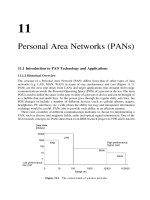
The concept of a Personal Area Network (PAN) differs from that of other types of data
networks (e.g. LAN, MAN, WAN) in terms of size, performance and cost (Figure 11.1).
PANs are the next step down from LANs and target applications that demand short-range
communications inside the Personal Operating Space (POS) of a person or device. The term
POS is used to define the space in the near vicinity of a person or device and can be thought of
as a bubble that surrounds him. As the person goes through his regular daily activities, his
POS changes to include a number of different devices (such as cellular phones, pagers,
headphones, PC interfaces, etc.) with whom the ability for easy and transparent information
exchange would be useful. PANs aim to provide such ability in an efficient manner.
There exist a number of different communication mediums to choose for implementing a
PAN, such as electric and magnetic fields, radio and optical signal transmission. One of the
first research concepts for PANs dates back to an IBM research project in 1996 and is known
Figure 11.1 The various kinds of wireless networks
as ‘Near-field Intra-body Communication PAN (NIC-PAN)’ [1]. This approach uses the
human body as the communication medium, which can conduct electricity due to its natural
content of salt. According to this approach, NIC-PAN-compliant devices worn by a user can
communicate with each other through the user’s body, thus no wires are needed. Furthermore,
a user wearing such a device can initiate communication with another device located on
another user by means of a simple handshake. In order to transmit data between devices
attached to the users’ bodies or clothing, the NIC-PAN device transmitter charges and
discharges the human body, thus resulting in an oscillating potential appearing between
the body and the environment. These changes of potential are picked up by the receiving
NIC-PAN device and thus a communication channel is established. The electrical current
used in this approach is approximately 1 nA, which is much lower than the natural electrical
current of the human body. In the context of this research, a small prototype was built, which
achieved data rates around 2.4 kbps.
However, the NIC-PAN approach did not evolve into something more than a research
project, whereas the true revolution in the area of PANs was brought about by the use of
wireless transmission-based PANs (WPANs
1
). The first attempt to define a standard for PANs
dates back to an Ericsson project in 1994, which aimed to find a solution for wireless
communication between mobile phones and related accessories (e.g. hands-free kits). This
project was named Bluetooth, after the king that united the Viking tribes. Bluetooth was a
promising approach and as a result, Nokia, Intel, Toshiba and IBM joined Ericsson to form
the Bluetooth Special Interest Group (SIG) in May 1998. The purpose of the Bluetooth SIG is
to develop a de facto standard for PANs that meets the communication needs of all mobile
computing and communication devices located in a reduced geographical space regardless of
their size or power budget. The size of the SIG has grown from the initial five members to
nearly 2000 others at the present day. Any interested company is allowed to join the SIG
provided that it lets all other members of the SIG use its patents royalty-free, in an effort to
keep the standard open. Version 1.0 of the Bluetooth specification was released by the SIG in
1999, followed by version 1.1 in 2001. Both these versions support 64 kbps voice channels
and asynchronous data channels either asymmetric, with a maximum data rate of 721 kbps in
one direction and 57.6 in the other or symmetric with a 432 kbps maximum rate in both
directions. Bluetooth uses Frequency Hopping Spread Spectrum (FHSS) modulation in the
2.4 GHz ISM band. The supported range is 10 m with the possibility of extending this to 100
m [2].
Another initiative from industry members to develop a PAN standard was made in 1997 by
the formation of the HomeRF Working Group. The primary goal of this group is to enable
interoperable wireless voice and data networking within the home. Version 1.0 of HomeRF
was published in 1999. It supported four 32 kbps voice connections and data rates up to 1.6
Mbps at ranges up to 50 m. Version 2.0 of HomeRF was released in 2001 and increased these
numbers to eight channels and 10 Mbps, respectively, making HomeRF more suitable than
Bluetooth for transmitting music, audio, video and other high data applications. However,
Bluetooth seems to have more industry backing. Like Bluetooth, HomeRF also supports
voice and asynchronous data channels using FHSS modulation in the 2.4 GHz ISM band.
After the appearance of the Bluetooth and HomeRF initiatives, IEEE also decided to join
the area of developing specifications for PANs. Thus the 802.15 Working Group [2–5] was
Wireless Networks300
1
Since all PAN technology alternatives today employ wireless transmission, the terms PAN and WPAN are used
in this book synonymously.
formed in March 1999, with the responsibility of defining physical and MAC layer specifica-
tions for PANs having low implementation complexity and low power consumption.
Although Working Group 802.11, which deals with Wireless LANs, already existed, it
was decided that a new Working Group was needed for PAN standardization. This is attrib-
uted to the fact that there is a much greater concern over power consumption, size, and
product cost in PANs stemming from the demands for PAN devices compared to WLAN
devices:
†
Less size and weight, in order to be easily carried or worn for long periods of time. On the
other hand, the size and weight of WLAN cards is a matter of secondary importance. This
is because WLAN devices are typically either attached to portable computers, which of
course are not carried by users all of the time, or to fixed desktop PCs.
†
Lower cost, in order not to burden the total cost of the device. PAN devices aim to provide
wireless connectivity to commercial electronic appliances. In order to enable small device
size, PAN functionality will be integrated within the devices. To earn market acceptance,
the cost burden of PAN functionality on the total cost of the device should be small. Users,
on the other hand, can buy WLAN cards separately, thus the impact of their cost is less
important.
There are four Task Groups (TGs) inside Working Group 802.15:
†
TG1. This group is working on a PAN standard based on Bluetooth.
†
TG2. This group aims to facilitate coexistence of PAN and WLAN networks.
†
TG3. This group aims to produce a PAN standard with data rates exceeding 20 Mbps,
while maintaining low cost, power consumption and interoperability with industry stan-
dards.
†
TG4. This group aims to produce a PAN standard that will enable low-rate operation while
achieving levels of power consumption so low, that a battery life of months or years will be
possible.
Due to the fact that industry consortia initiatives for PAN standards development preceded
the initiative of IEEE, a key mission of the 802.15 Working Group will be to work closely
with such consortia, such as Bluetooth and HomeRF, in order to achieve interoperability for
PANs coexisting in a shared wireless medium.
11.1.2 PAN Concerns
There are certain issues that need to be taken into account when designing a PAN. The most
obvious one affects all types of wireless networks and concerns the increased Bit Error Rate
(BER) of the wireless medium. As has been mentioned, the primary reason for the increased
BER is atmospheric noise, physical obstructions found in the signal’s path, multipath propa-
gation and interference from other systems. The primary source of interference in the 2.4 GHz
ISM band in which PANs operate, comes both from narrowband and wideband sources, such
as microwave ovens. Apart from the good interference avoidance properties of SS modula-
tion, which is employed for unlicensed transmission in the 2.4 GHz ISM band, Automatic
Repeat Requests (ARQ) and Forward Error Control (FEC) techniques can also be used in this
direction. Furthermore, PANs have to deal with interference from collocated PANs and
WLANs, although this should not be a big problem due to the use of FHSS modulation.
Personal Area Networks (PANs) 301
PANs should provide full communication capability between all devices in the POS of a
person. However, two PAN devices that initiate communication inside the POS should not
interfere with other devices when this is not wanted. Consider for example the case of a
person entering a conference room. After sitting in a chair, a PAN interface nearby could
communicate with a handheld device of the person and deliver to him the information he
wants. However, automatic initiation of communication with the devices of nearby confer-
ence attendants may not be desirable for privacy reasons.
A person carrying a PAN-enabled device could find him-/herself in a diverse range of
situations, whether personal or professional, that demand information delivery through the
PAN device. Therefore, PAN devices should be compatible to enable information exchange
in all cases. Returning to the conference example, imagine two attendants wanting to
exchange information, discovering that their systems are not compatible and thus they
need to exchange the information on paper. In such case, the market community would
see PANs as a waste of time and money. Compatibility not only involves following a specific
PAN standard but also software compatibility. For example, the file formats on each of the
above devices should be able to be read by both devices.
PAN-enabled devices will be typically be carried by people for long periods of time. Thus,
they need to be small enough in order to be carried around without burdening. PAN devices
should therefore be as small and light as possible. Their energy efficiency should be enough in
order not to trouble the user with frequent recharging of batteries, while maintaining a low
device weight. Therefore, both low power consumption devices and high capacity batteries
are desirable. Furthermore, the efficiency in terms of size and weight should not come at an
expense over the price of PAN devices, in order to enable market acceptance.
Security issues are also crucial in PANs. Communications should be secure and difficult to
eavesdrop. Consider the case of a malicious user approaching pedestrians carrying PAN
devices. The unpleasant ‘Big Brother’ scenario of Orwell’s 1984 is obvious here and should
be as difficult to achieve as possible. It should be very hard for the malicious user to obtain
information regarding the unsuspected pedestrians, such as their names, home addresses, etc.
Therefore, robust authentication and encryption schemes should be developed in an effort to
prevent unauthorized initiation of communication and eavesdropping. These schemes should
be developed while keeping in mind the relatively low processing and power capabilities of
PAN devices which stem from the requirements for reduced cost, size and weight.
Finally, as in the case of all wireless networks human safety issues are of great concern. A
PAN device will typically be very close to the user for long periods of time and therefore even
small dangers could potentially have some impact on the user over time. The good thing here
is that PAN (like WLAN) devices typically transmit at power levels up to 0.5 W. Despite the
fact that a final answer to the question of radiation threats to human health has yet to be given,
it is reassuring for the consumers to know that the operating power levels of a PAN device are
substantially lower than the 600-mW to 3-W range of common cellular phones.
11.1.3 PAN Applications
The main goal of PANs is freedom from cables and easy sharing of information between all
kinds of wireless devices. The number of different possible applications can be very large. In
the following we outline a representative set:
Wireless Networks302
†
Personal device synchronization. Automatic data synchronization between mobile wire-
less equipment such as a mobile phone, notebook PC, etc. that execute similar applica-
tions.
†
Ad hoc connectivity. Transferring files, and other information to another user’s PAN-
enabled device.
†
Cordless computer. Wireless interfacing of devices like mice, keyboards, game pads to the
computer.
†
Cordless peripherals. Access to a variety of wireless peripherals including printers, scan-
ners, fax, copier, storage systems, etc.
†
Localized wireless LAN access. PAN-enabled devices can gain access to services offered
by wired LANs through PAN-compatible Access Points (APs).
†
Internet access. Downloads of email or browsing a web page using a PAN-enabled device,
such as a mobile phone.
†
Wireless synchronization. Synchronization of portable devices with the stationary servers
via PAN APs.
†
Cordless telephony/headset. A user selects a contact name from a handheld, the handheld
wirelessly prompts the mobile phone in its proximity to dial the number and the audio
from the call is wirelessly forwarded to the user’s headset.
†
Home automation. Seamless transfer of commands to PAN-enabled home devices. For
example, automatic unlocking of the door upon the arrival of the user at his home, or
automatic tuning of the television to the user’s favorite channel upon his entrance to the
room.
†
Electronic purchases/reservations. PAN devices can be used to electronically book tick-
ets. For example, the PAN device of a user can be programmed to instantly initiate a
request for booking a ticket for a specific flight when the user enters the airport, thus
avoiding the long queues and waiting times of the traditional booking procedures.
†
Emergency situations. Medical devices with PAN interfaces can be used in order to
increase the safety of patients. For example, pacemakers could be monitored and
controlled remotely through PAN interfaces, or can be programmed to immediately call
an ambulance while also transmitting the patient’s medical condition in the case of a heart
attack or other serious health problem.
11.1.4 Scope of the Chapter
The remainder of this chapter provides a detailed presentation of technological alternatives in
the PAN area. Section 11.2 presents the Bluetooth specification and discusses, among others,
the way Bluetooth devices establish connections and exchange data. Furthermore, Blue-
tooth’s provisions on security and power management are discussed. Section 11.3 is a similar
discussion on the HomeRF standard. The chapter ends with a brief summary Section 11.4.
11.2 Commercial Alternatives: Bluetooth
11.2.1 The Bluetooth Specification
The Bluetooth specification 1.1 [6–9] comprises two parts: core and profiles. The core
Personal Area Networks (PANs) 303
specification defines the layers of the Bluetooth Protocol stack. The aim of the stack (shown
in Figure 11.2) is to provide a common data link and physical layer to applications and high-
level protocols that communicate over the Bluetooth wireless link and maximize reuse of
existing protocols at the higher layers. The protocols that run at different layers of the stack
can be categorized into three groups: Bluetooth core, cable replacement protocols
(RFCOMM), telephony control protocols (TCS and AT commands) and adopted protocols
(such as IP, PPP, etc.). From these protocols, only the core protocols, RFCOMM and TCS are
Bluetooth-specific protocols (those run at the shaded layers of Figure 11.2). The layers of the
stack are summarized below:
†
The radio layer provides the electrical specifications in order to send and receive
bitstreams over the wireless channel. These specifications are discussed in Section 11.2.2.
†
The baseband layer enables the operation of the Bluetooth links (described in Section
11.2.4) over the wireless medium. This layer is also responsible for framing, flow control
and timing operations and it also manages the links between communicating Bluetooth
devices.
†
The Link Management (LM) layer runs the Link Management Protocol (LMP). This is an
entity responsible for managing connection states, ensuring access fairness, performing
power management and providing authentication and encryption services to upper layers.
Power management issues are discussed in Section 11.2.7 while security is discussed in
Section 11.2.8.
†
The Logical Link And Adaptation Layer (L2CAP) provides connection-oriented and
connectionless data services to upper layer protocols with protocol multiplexing capabil-
ity, segmentation and reassembly (SAR) operations, and group abstractions. L2CAP
permits higher-level protocols and applications to transmit and receive L2CAP packets
up to 64 kilobytes in length. L2CAP supports only data traffic. As can be seen from Figure
11.2, audio data is not conveyed through L2CAP but is mapped directly to the baseband
layer. Thus, data for audio connections is exchanged directly between the baseband layers
of Bluetooth devices.
†
The service discovery layer runs the Service Discovery Prototcol (SDP), which is used in
Wireless Networks304
Figure 11.2 The Bluetooth protocol stack. Shaded layers implement Bluetooth-specific protocols
order for a Bluetooth device to learn about services on offer and neighboring device
information. Using SDP, neighbors of a device can be queried and if some requirements
are met, a connection can be established.
†
The RFCOMM layer runs a serial line RS-232 control and data signal emulation protocol.
It is used for cable replacement, offering transport capabilities over the wireless link to
applications that use serial lines as a transport mechanism.
†
The TCS layer defines call control signaling procedures for the establishment of voice and
data calls between Bluetooth devices.
†
The Host Controller Interface (HCI) is not a stack layer but an interface that provides the
means for accessing the Bluetooth hardware capabilities.
†
Layers that implement non-Bluetooth specific protocols (OBEX, WAP, etc.) are used to
enable high-layer application functionality.
The profiles part of the specification is used to classify Bluetooth applications into nine
application profiles, with each profile implementing only a certain set of the stack’s protocols.
This approach has received some criticism, which supports that the Bluetooth specification is
essentially a set of nine standards instead of one, with the number likely to rise as new
application profiles are added. However, the existence of application profiles aims to ensure
interoperability between Bluetooth devices. In order for a device to be certified for a specific
Bluetooth application, it has to follow the corresponding profile. Furthermore, the production
of devices for a specific application means that the device could support only some of the
application profiles, thus reducing its overall cost. Apart from the nine application profiles,
version 1.1 of the Bluetooth specification also supports four system profiles, which include
functionality common to one or more application profiles. The thirteen profiles are summar-
ized below. Some of the profiles can exist only if they implement other profiles, as shown in
Figure 11.3.
Personal Area Networks (PANs) 305
Figure 11.3 The Bluetooth profiles
†
Generic access profile. This system profile is responsible for link maintenance between
devices. This profile is not useful for supporting any useful application by itself, however,
it needs to be supported in every Bluetooth device since it includes the functionality
needed to use all the other system profiles.
†
Service discovery application profile. This is another system profile that enables users to
access the Service Discovery Protocol (SDP) in order to find out which applications are
supported by a specific device. The support of the service discovery application profile is
optional. If, however, this system profile is not supported, only applications can access the
SDP, not users.
†
Intercom profile. This application profile supports direct voice communication between
two Bluetooth devices within range of each other.
†
Cordless telephony profile. This application profile is designed in order to support the ‘3-
in-1 phone’ concept, meaning that a Bluetooth-compliant telephone can be used either as
an intercom (communicating directly with another Bluetooth device), cordless (fixed-
location) or mobile phone.
†
Serial port profile. This system profile emulates RS232 and USB serial ports in order to
allow applications to exchange data over a serial link.
†
Headset profile. This application profile uses the serial port profile to provide connections
between Bluetooth-enabled computers or mobile phones and Bluetooth-enabled wireless
headset microphones.
†
Dial-up networking profile. This application profile uses the serial port profile to provide
dial-up connections via Bluetooth-enabled cellular phones.
†
Fax profile. This application profile uses the serial port profile to enable computers to send
a fax via a Bluetooth-enabled cellular phone.
†
LAN access profile. This application profile enables Bluetooth devices either to form small
IP networks among themselves or connect to traditional LANs through Access Points (APs).
†
Generic object exchange profile. This system profile defines the functionality needed for
Bluetooth devices to support object exchanges.
†
Object push profile. This application profile defines the functionality needed to support
‘pushed’ data. Examples of such information are advertisements and news distribution.
†
File transfer profile. This application profile enables file transfers between Bluetooth
devices.
†
Synchronization profile. This application profile enables automatic data synchronization
between Bluetooth devices. For example, it can be used to synchronize address books
between a desktop computer and a portable.
11.2.2 The Bluetooth Radio Channel
The Bluetooth radio channel [7], enabled by the radio layer, provides the electrical interface
for the transfer of Bluetooth packets over the wireless medium. The radio channel operates at
the 2.4 GHz ISM band by performing frequency hopping through a set of 79 (US and Europe)
or 23 (Spain, France and Japan) RF channels spaced 1 MHz apart. The wireless link
comprises time slots of 0.625 ms length each, with each slot corresponding to a hop
frequency. The nominal hop rate is 1600 hops/s. At each hop, the transmitted signal is
modulated using GFSK with a binary one being represented by a positive frequency shift
Wireless Networks306
and a binary zero by a negative frequency shift. Despite the fact that this configuration
provides link speeds up to 1 Mbps, the effective data transfer speeds offered are lower.
This is because different protocol layers use parts of the packet data payload to add header
information for purposes of communication with peer layers. More efficient modulation
schemes could obviously achieve higher speeds, however, the use of GFSK is preferred as
it allows for low-cost device implementations.
Depending on the transmitted power, Bluetooth devices can be classified into three classes,
as shown in Figure 11.4. Power control mechanisms can be used to optimize the transmitter’s
power output. This is done by measuring the received signal strength and relaying LMP
commands to the respective transmitter indicating whether power should be increased or
decreased. Power control is required for class 1 equipment, whereas it is optional for equip-
ment of classes 2 and 3. Using power class 1 a range of 100 m can be achieved in a Bluetooth
system [2].
11.2.3 Piconets and Scatternets
When two Bluetooth devices want to connect, the one requesting the connection, is known as
the master, whereas the other is known as the slave. The master always controls the link
created between the two devices. The master–slave relationship is good only for a specific
link establishment, since any Bluetooth unit can be either master or slave. A given master can
maintain up to seven connections to active slaves. As a result, several very small networks,
called piconets, can be established. However, if the master wants to open connections to more
than seven slaves it can instruct one or more active slaves to ‘sleep’ for a specified period of
time by putting them in the low-power PARK mode (described in Section 11.2.7). Then the
master can admit new slaves into the piconet for the period the old set of slaves were put to
sleep. Thus, piconets of many devices can be formed.
A piconet is shown in Figure 11.5. Devices inside a piconet hop together according to the
master’s clock value and its 48-bit device ID. The way the hopping sequence is used and the
starting point within that sequence is selected is shown in Figure 11.6. The first parameter
defines the hopping sequence used for FHSS transmission inside the piconet. The second
parameter is derived from the native clock of the master and defines the phase within that
sequence. Slave to slave transmission is not supported inside a piconet. If two slaves need to
communicate, they either have to form a separate piconet in which one of them is the master,
or use a higher layer protocol, such as IP in order to relay messages through the piconet’s
master.
A number of piconets can coexist in the same area. This coexistence is enabled due to the
use of FHSS transmission. Since the hopping sequences used in Bluetooth are pseudorandom,
different coexisting piconets will use different hopping sequences, resulting in a low prob-
Personal Area Networks (PANs) 307
Figure 11.4 Power classes for Bluetooth devices
ability of hop collisions. Still, if such a case occurs, a Bluetooth device can recognize and thus
ignore packets originating from collocated networks by checking the access code field on the
received packets which is different for every piconet, as we explain later. However, when a
large number of piconets coexist in the same area, this probability rises and the performance
of each piconet degrades.
A collection of overlapping piconets is called a scatternet. A scatternet will typically
contain devices that participate in one or more piconets. Devices participating in two or
more piconets are known as bridge devices and participate in each piconet in a time-sharing
manner. After spending its time inside a piconet, a bridge device will change its hopping
sequence to that of the new piconet in order to join it. Furthermore, it will select the starting
point within that sequence based on the clock value of the master of the new piconet. By
alternating among several piconets and buffering packets, bridge nodes can forward packets
from one piconet to another. A bridge node that participates in several piconets can be either:
†
Slave in all the piconets. In this case, when leaving the old piconet, the slave has to inform
the master for the duration of its absence.
†
Master in one piconet and slave in all others. In this case, all traffic in the old piconet is
Wireless Networks308
Figure 11.6 Combination of the master’s device ID and native clock values to select the hopping
sequence to be used and its starting point
Figure 11.5 A piconet formed by six devices
suspended until the master returns to the piconet. The suspension of traffic is achieved by
putting the piconet’s slaves into the low-power HOLD mode (described in Section 11.2.7).
A bridge node cannot obviously be master in more than one piconet, since this would make
these piconets use the same hopping sequence and thus collide.
Figure 11.7 shows a scatternet, where the participating nodes fall into four categories.
Nodes in category A are masters within a single piconet, nodes in category B are slaves within
a single piconet, nodes in category C are participating in two piconets as slaves and nodes in
category D are participating in two piconets as slaves in the one and master in the other.
Obviously, nodes in categories C and D are bridge nodes between the piconets in which they
participate. Techniques for efficient interpiconet communication and efficient formation of
scatternets from overlapping piconets are under development [10–12].
11.2.4 Inquiry, Paging and Link Establishment
Bluetooth devices can communicate as soon as they are within range of one another.
However, since the in-range neighbors of a Bluetooth device change with time, a procedure
that informs a device about its neighbors is needed. This procedure is carried out by issuing
inquiries. Although an inquiry is a fairly simple procedure, it becomes complicated due to the
use of FHSS at the physical layer. Assume that device A is within range of device B and
wants to acquire knowledge about its neighbors. Since the hopping sequence of a link is
defined by the master’s device ID and clock values, A and B cannot exchange messages until
they agree to a common hopping sequence as well as a common phase within that sequence.
In order for two devices to exchange messages during the inquiry procedure, Bluetooth
defines a specific hopping sequence to be used for inquiries by all devices. Furthermore,
since there may be a phase uncertainty between A and B since those devices may not be
completely synchronized (meaning that they start from a different hop inside the hopping
sequence due to the differing Clock values of A and B), the sender hops faster than the
listener, by transmitting a signal on each hop and listening between successive transmissions
for an answer. The term Frequency Synchronization delay (or FS delay) refers to the time
elapsed until the sender (A in this case) transmits at the frequency the receiver (B) is currently
Personal Area Networks (PANs) 309
Figure 11.7 A scatternet formed by four piconets