Second Generation (2G) Cellular Systems
Bạn đang xem bản rút gọn của tài liệu. Xem và tải ngay bản đầy đủ của tài liệu tại đây (399.3 KB, 40 trang )
4
Second Generation (2G) Cellular
Systems
4.1 Introduction
As was mentioned in the previous chapter, the era of mobile telephony began with the
development and operation of the First Generation (1G) of cellular systems in the late
1970s. Although these systems have found widespread use and are still used nowadays,
the evolution of technology has enabled the industry to move to Second Generation (2G)
systems, the successors of 1G systems. 2G systems overcome many of the deficiencies of 1G
systems mentioned in the previous chapter. Their increased capabilities stem from the fact
that, contrary to 1G systems, 2G systems are completely digital. Compared to analog, digital
technology has a number of advantages:
† Encryption. Digitized traffic can be easily encrypted in order to provide privacy and
security. Encrypted signals cannot be intercepted and overheard by unauthorized parties
(at least not without very powerful equipment). On the other hand, powerful encryption is
not possible in analog systems, which most of the time transmit data without any protection. Thus, digital systems provide an increased potential for securing the user’s traffic and
preventing unauthorized network access.
† Use of error correction. In digital systems, it is possible to apply error detection and error
correction techniques to the user traffic. Using these techniques the receiver can detect and
correct bit errors, thus enhancing transmission reliability. This obviously leads to signals
with little or no corruption, which of course translates into (a) better voice call qualities,
(b) higher speeds for data applications, and (c) efficient spectrum use, since fewer retransmissions are bound to occur when error correction and error detection techniques are used.
Furthermore, digital data can be compressed, which increases the efficiency of spectrum
use even more. It is actually this increased efficiency that enables 2G systems to support
more users per base station per MHz of spectrum than 1G systems, thus allowing operators
to provide service in high-density areas more economically.
† In analog systems, each RF carrier is dedicated to a single user, regardless of whether the
user is active (speaking) or not (idle within the call). In digital systems each RF carrier is
shared by more than one user, either by using different time slots or different codes per
user. Slots or codes are assigned to users only when they have traffic (either voice or data)
to send.
112
Wireless Networks
The movement from analog to digital systems was made possible due to the development of
techniques for low-rate digital speech coding and the continuous increase in the device
density of integrated circuits. Contrary to 1G systems, which employ FDMA for user separation, 2G systems allow the use of Time Division Multiple Access (TDMA) and Code Division
Multiple Access (CDMA) as well. Since the standards that will be discussed in this chapter
employ either TDMA or CDMA (sometimes with a combination with FDMA), we briefly
revisit the three approaches.
In order to accommodate various nodes inside the same cellular network, FDMA divides
the available spectrum into subbands each of which are used by one or more users. Each user
is allocated a dedicated channel (subband), different in frequency from the channels allocated
to other users. When the number of users is small relative to the number of channels, this
allocation can be static, however, for many users dynamic channel allocation schemes are
necessary. In cellular systems, channel allocations typically occur in pairs. Thus, for each
active mobile user, two channels are allocated, one for the traffic from the user to the Base
Station (BS) and one for the traffic from the BS to the user. The frequency of the first channel
is known as the uplink (or reverse link) and that of the second channel is known as the
downlink (or forward link). For an uplink/downlink pair, uplink channels typically operate on
a lower frequency than the downlink one in an effort to preserve energy at the mobile nodes.
This is because higher frequencies suffer greater attenuation than lower frequencies and
consequently demand increased transmission power to compensate for the loss. By using
low frequency channels for the uplink, mobile nodes can operate at lower power levels and
thus preserve energy. Due to the fact that pairs of uplink/downlink channels are allocated by
regulation agencies, most of the time they are of the same bandwidth. This fact makes FDMA
relatively inefficient since in most systems the traffic on the downlink is much more heavier
than that in the uplink. Thus, the bandwidth of the uplink channel is not fully used.
TDMA is the technology of choice for a wide range of second generation cellular systems
such as GSM, IS-54 and DECT. TDMA divides a band into several time slots and the
resulting structure is known as the TDMA frame. In this, each active node is assigned one
(or more) slots for transmission of its traffic. Nodes are notified of the slot number that has
been assigned to them, so they know how much to wait within the TDMA frame before
transmission. Uplink and downlink channels in TDMA can either occur in different frequency
bands (FDD-TDMA) or time-multiplexed in the same band (TDD-TDMA). The latter technique obviously has the advantage of easy trading uplink to downlink bandwidth for supporting asymmetrical traffic patterns.
TDMA is essentially a half-duplex technique, since for a pair of communicating nodes, at a
specific time, only one of the nodes can transmit. Nevertheless, slot duration is so small that
the illusion of two-way communication is created. The short slot duration, however, imposes
strict synchronization problems in TDMA systems. This is due to the fact that if nodes are far
from one another, the propagation delay can cause a node to miss its turn. In order to protect
inter-slot interference due to different propagation paths to mobiles being assigned adjacent
slots, TDMA systems use guard intervals in the time domain to ensure proper operation.
Instead of sharing the available bandwidth either in frequency or time, CDMA places all
nodes in the same bandwidth at the same time. The transmissions of various users are
separated through a unique code that has been assigned to each user.
All nodes are assigned a specific n-bit code. The value of parameter n is known as the
system’s chip rate. The various codes assigned to nodes are orthogonal to one another,
Second Generation (2G) Cellular Systems
113
meaning that the normalized inner product of the vector representations of any pair of codes
equals zero. Furthermore, the normalized inner product of the vector representation of any
code with itself and the 1s complement of itself equals 1 and 21, respectively. Nodes can
transmit simultaneously using their code and this code is used to extract the user’s traffic at
the receiver. Obviously, the receiver knows the codes of each user in order to perform the
decoding.
The use of TDMA or CDMA in cellular systems offers a number of advantages:
†
†
†
†
Natural integration with the evolving digital wireline network.
Flexibility for mixed voice/data communication and the support of new services.
Potential for further capacity increases as reduced rate speech coders are introduced.
Reduced RF transmit power (which obviously translates into increasing battery life in
handsets).
† Reduced system complexity (mobile-assisted handoffs, fewer radio transceivers).
4.1.1 Scope of the Chapter
The remainder of this chapter describes several 2G standards. D-AMPS, the 2G TDMA
system that is used in North America and descends from the 1G AMPS is described in Section
4.2. CdmaOne, which is the only 2G system based on CDMA is discussed in Section 4.3. The
widely used Global system for Mobile Communications (GSM) is described in Section 4.4.
Section 4.5 describes IS-41, which is actually not a 2G standard but rather a protocol that
operates on the network side of North American cellular networks. Section 4.6 is devoted to
data transmission over 2G systems and discusses a number of approaches, including GRPS,
HSCSD, cdmaTwo, etc. Furthermore, Section 4.6 discusses the problems faced by TCP in a
wireless environment, mobileIP, an extension of the Internet Protocol (IP) that supports
terminal mobility and the Wireless Access Protocol (WAP). Section 4.7 discusses Cordless
Telephony (CT) including the Digital European Cordless Telecommunications Standard
(DECT) and Personal Handyphone System (PHS) standards. The chapter ends with a brief
summary in Section 4.8.
4.2 D-AMPS
In an effort to increase the performance of AMPS a standard known as D-AMPS (standard
name is IS-54) was developed. D-AMPS maintains the 30-kHz channel spacing of AMPS and
is actually an overlay of digital channels over AMPS. D-AMPS was designed in a way that
enables manufacturing of dual-mode (AMPS and D-AMPS) terminals. Thus, the development of D-AMPS has led to a hybrid standard. This is necessary to accommodate roaming
subscribers, given the large embedded base of AMPS equipment.
The main difference between AMPS and D-AMPS is that the latter overlays digital channels over the 30 kHz carriers of AMPS. Each such digital channel can support three times the
users that are supported by AMPS with the same carrier. Thus, D-AMPS can be seen as an
overlay on AMPS that ‘steals’ some carriers and changes them to carry digital traffic.
Obviously, this does not affect the underlying AMPS network, which can continue to serve
regular AMPS users. In fact, each D-AMPS MS initially accesses the network via the traditional AMPS analog control channels. Then the MS can make a request to be assigned a
114
Wireless Networks
digital channel and if such a channel is available, it is allocated to the D-AMPS MS; otherwise the MS will operate in AMPS mode.
Finally, as far as handoffs are concerned, D-AMPS supports Mobile Assisted Handoff
(MAHO). MSs make measurements of the signal strength from various neighboring BSs
and report these measurements to the network, which uses this information to decide whether
a handoff will be performed, and to which BS. The difference with AMPS is that in AMPS,
MSs do not perform signal strength measurements. Rather these measurements are made by
the BSs as can be seen in Chapter 2 from the sequence of events that describes a handoff in
AMPS.
Both D-AMPS and its successor IS-136 support voice as well as data services. Supported
speeds for data services are up to 9.6 kbps.
4.2.1 Speech Coding
D-AMPS utilizes Vector-Sum Excited Linear Predictive Coding (VSELP). This method
breaks the PCM digitized voice bit-stream into parts corresponding to 20 ms speech intervals.
Each such bitstream forms the input to a codebook whose output replaces the input bitstream
with the codeword that is closest to the actual value of the input bitstream. This codeword is
what will be transmitted over the wireless link. Each codeword will be later provided with
protection against the fading wireless environment. This protection comprises: (a) a CRC
operation on the most significant bits of each speech coder output; (b) convolutional coding to
protect the most vulnerable bits of the speech coder output; and (c) interleaving the contents
of each coder output over two time slots. Each digital channel provides a raw bit rate of 48.6
kbps, achieved using p/4 DQPSK.
4.2.2 Radio Transmission Characteristics
D-AMPS operates at the same frequency band with AMPS. Uplink digital channels occur in
the 824–849 band and downlink ones in the 869–894 band. Each digital channel is organized
into 40 ms frames and each frame comprises six 6.67 ms time slots. Each user can use either 2
slots (either 1 and 4, 2 and 5 or 3 and 6) or 1 slot within each frame. The first configuration is
used with the full-rate voice codec, producing transmission of actual voice information up to
7.95 kbps (5.05 kbps with Forward Error Correction (FEC)). The second configuration is used
with the half-rate voice codec producing transmission of actual voice information up to 3.73
kbps (2.37 kbps with FEC). The corresponding values for data speeds are 9.6 without FEC
and 3.4 kbps with FEC.
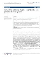
The overall access method is shown in Figure 4.1. It can be seen that the uplink and
downlink slots have a slightly different internal arrangement. The slot parts are described
below:
† The training part. This part has enables the MS and BS to ‘learn’ the channel. This is
because a signal is bound to arrive at the receiver over a number of paths due to reflections
from objects in the environment. Thus, equalization is used to extract the desired signal
from the unwanted reflections. The IS-54 standard also provides for an adaptive equalizer
to mitigate the intersymbol interference caused by large delay spreads, but due to the
relatively low channel rate (24.3 kbaud), the equalizer will be unnecessary in many
situations.
Second Generation (2G) Cellular Systems
Figure 4.1
115
Structure of IS-54 slot and frame
† The traffic (data) parts. These parts carry user traffic, either voice or data-related. As the
channels are digital, user traffic can be encoded or encrypted, thus the whole traffic part is
not always entirely dedicated to the transfer of user data but also contains encryption/
coding overhead.
† The guard part. This provides guard intervals in the time domain in order to separate a slot
from the previous slot and the next slot. The need for these parts is due to propagation
delay, which can cause a node to miss its slot when nodes are very far from one another.
† The ramp bits. These are used to ramp up and down the signal during periods where the
signal is in transition.
† The control parts. These carry control signaling via the channel shown in parentheses.
Uplink and downlink frames are offset in time by 8.518 ms. As the uplink and downlink
occur in different carriers, this offset allows an MS to operate at half-duplex mode since with
this arrangement MSs never transmit and receive at the same time.
4.2.3 Channels
D-AMPS reuses the AMPS channels described in Chapter 2. However, it also introduces
some new digital channels. The channel definitions for AMPS are as follows:
† Forward Control Channel (FOCC). Same as AMPS.
† Forward Voice Channel (FVC). Same as AMPS. The analog channel carrying voice traffic
from the BS to the MS.
† Forward Digital Traffic Channel (FDTC). This is a BS to MS channel carrying digital
traffic (both user data and control data). It consists of the Fast Associated Control Channel
(FACCH) and Slow Associated Control Channel (SACCH). FACCH is a blank-and-burst
operation, meaning that the traffic channel is pre-empted by control signaling. SACCH is a
Wireless Networks
116
continuous channel also associated with control signaling. However, it differs from
FACCH in that a certain amount of bandwidth is allocated a priori to SACCH.
† Reverse Control Channel (RECC). Same as AMPS.
† Forward Voice Channel (RVC). Same as AMPS. The analog channel carrying voice traffic
from the MS to the BS.
† Reverse Digital Traffic Channel (RDTC). This is an MS to BS channel carrying digital
traffic (both user data and control data). It consists of a FACCH and SACCH.
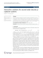
4.2.4 IS-136
IS-136 is an upgrade of AMPS that also operates in the 800 MHz bands. However, there are
planned upgrades to the 1900 band. While D-AMPS is a digital overlay over AMPS, IS-136 is
a fully digital standard. IS-136 has much in common with GSM (such as convolutional
coding, interleaving, etc.). However, their air interfaces are incompatible. Due to the similarities between GSM and IS-136, we do not make a detailed presentation of the former. Rather,
we present the organization of the air interface of IS-136, which as can be seen from Figure
4.2 builds on top of that of D-AMPS.
Figure 4.2
Structure of IS-136 slot, frame and multiframe
Second Generation (2G) Cellular Systems
117
4.3 cdmaOne (IS-95)
In 1993 cdmaOne, a 2G system also known as IS-95, has been standardized and the first
commercial systems were deployed in South Korea and Hong Kong in 1995, followed by
deployment in the United States in 1996. cdmaOne utilizes Code Division Multiple Access
(CDMA). In cdmaOne, multiple mobiles in a cell, whose signals are distinguished by spreading them with different codes, simultaneously use a frequency channel. Thus, neighboring
cells can use the same frequencies, unlike all other standards discussed so far. cdmaOne is
incompatible with IS-136 and its deployment in the United States started in 1995. Both IS136 and cdmaOne operate in the same bands with AMPS. cdmaOne is designed to support
dual-mode terminals that can operate either under an cdmaOne network or an AMPS
network. cdmaOne supports data traffic at rates of 4.8 and 14.4 kbps.
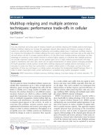
4.3.1 cdmaOne Protocol Architecture
Figure 4.3 shows the protocol architecture of the lower two layers of cdmaOne and its
correspondence to the layers of the OSI model. Layer 1 obviously deals with the actual
radio transmission, frequency use, etc. These issues will be discussed briefly in the next
subsection. Layer 2 offers a best effort delivery of voice and data packets. The MAC sublayer
of this layer also performs channel management. This sublayer maintains a finite-state
Figure 4.3 cdmaOne protocol architecture
Wireless Networks
118
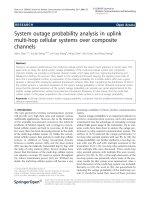
Figure 4.4
cdmaOne MAC states
machine with the two states shown in Figure 4.4. Reflecting the status of packet or circuit data
transmissions, a different machine is maintained for each transmission. cdmaOne mobiles
maintain all their channels and go to the dormant state after a ‘big’ timeout (big period during
which the MS is idle). In this state, mobiles do not maintain any channels. Thus, there exists
no mechanism for sending user data while in the dormant state; rather the mobile must request
channel assignment, thus incurring an overhead for infrequent data bursts. Upon having
traffic to send, they return to the active state where channels are assigned to the mobile.
Finally, data originating from different sources are multiplexed and handed for transmission
to the physical layer.
4.3.2 Network Architecture-Radio Transmission
As mentioned above, cdmaOne reuses the AMPS spectrum in the 800 MHz band. cdmaOne
uses a channel width of 1.228 MHz both on the uplink and downlink. Therefore, 41 30 kHz
AMPS channels are grouped together for cdmaOne operation. A significant difference
between cdmaOne and the other cellular standards stems from the fact that in cdmaOne,
the same frequency is reused in all cells of the system. This leads to a frequency reuse factor
of 1 and is due to the fact that cdmaOne identifies the transmissions of different mobiles via
the different spreading codes that identify each mobile. Both cdmaOne BSs and MSs utilize
antennas that have more than one element (RAKE receivers) in order to combat the fading
wireless medium via space diversity.
The use of CDMA for user separation imposes the need for precise synchronization
between BSs in order to avoid too much interference. This synchronization problem is solved
via the use of the Global Positioning System (GPS) receivers at each BS. GPS receivers
provide very accurate system timing. Once the BSs are synchronized, it is their responsibility
to provide timing information to the MSs as well. This is achieved by conveying from the BSs
to the MSs a parameter identifying the system time, offset by the one way or round-trip delay
of the transmission. In this way, it is ensured that BSs and MSs remain synchronized.
Finally, as far as the network side is concerned, cdmaOne utilizes the IS-41 network
protocol that is described in a later section.
4.3.3 Channels
4.3.3.1 Downlink Channels
Downlink channels are those carrying traffic from the BS to the MSs. The cdmaOne
downlink is composed of 64 channels. These logical channels are distinguished from
each other by using different CDMA spreading codes, W0 to W63. The spreading code
is an orthogonal code, or called Walsh function. The cdmaOne downlink comprises
Second Generation (2G) Cellular Systems
119
common control and dedicated traffic channels, the most important of which are summarized below.
† Pilot channel. This channel provides the timing information to the MS regarding the
downlink and signal strength comparisons between BSs. The actual content of the pilot
channel is a continuous stream of 0s at a rate of 19.2 kbps.
† Sync channel. This optional channel is used to transmit synchronization messages to MSs.
The sync channel is usually present, but may be omitted in very small cells. In that case, a
mobile will get synchronization information from a neighboring cell. The channel operates
at a rate of 1200 bps.
† Paging channel. This is an optional channel. There are up to seven paging channels on the
downlink which can carry four major types of messages: overhead, paging, order, and
channel assignment. This channel operates at one of the following data rates: 2400, 4800,
or 9600 bps.
† Traffic channels. Traffic channels carry user data, at 1200, 2400, 4800, or 9600 bps. All
traffic channels are spread by a long code (PN code), which provides discrimination
between mobile stations.
Except for the pilot channel, all channels on the downlink are coded and interleaved. The
vocoder uses the Code Excited Linear Predictive (CELP) algorithm. The vocoder is sensitive
to the amount of speech activity present on its input, and its output will appear at one of four
available rates. The bit rate of the vocoder changes in proportion to how active the speech
input may be at any time. The rate may vary every 20 ms. The output of the vocoder is first
encoded by the convolutional encoder into a constant 19.2 ksps (1000 symbols/second)
binary stream, each data bit is represented by two symbols, with one redundancy bit inserted
(rate 1/2). The output of the convolutional coder is input to a repetition function, which is
used to repeat the data pattern of reduced rates (1200, 2400, or 4800 bps) to form a constant
output rate of 19.2 ksps. The encoded binary stream is then interleaved randomly by the
interleaver (at an interval of 20 ms) into frames (frame interleaving). The purpose of using
interleaving is to combat the multipath fading environment, which causes burst errors on the
radio channel. The output of the interleaver is then modulo-2-added to a 19.2 kcps (1000
chips/second) scrambling code from a 1/64 decimator. The decimator selects every 64th bit
from a ‘long code’ generator running at 1.2288 Mcps. The ‘long code’ generator creates a
very long codes (2 42 2 1 bits) based on the user-specific information, such as the Mobile
Identity Number (MIN) or the user’s Electronic Serial Number (ESN). Long codes provide a
very high level of security, because of the long length. This information is also made available to the network when the MS sends its handshaking information to the BS. After modulated by a long code, the resulting 19.2 ksps data stream is spread by a Walsh function running
at a rate of 1.2288 Mcps. Walsh spreading provides every channel with a unique identification
number. Finally, the spread 1.2288 Mcps signal is spread one more time by a short code
running at 1.2288 Mcps. Short code is also a Pseudonoise (PN) code, and is 2 15 2 1 bits in
length. All base stations use the same short code, but with different offsets. There exist 512
different offsets, thus this scheme can uniquely identify 512 different cdmaOne BSs. A
mobile can easily distinguish transmissions from two different base stations by their shortcode offsets. The resulting signal is transmitted over the wireless medium via Quadrature
Phase Shift Keying (QPSK) modulation.
120
Wireless Networks
4.3.3.2 Uplink Channels
There are two types of uplink channels, access and traffic. There can be up to 32 access
channels on the uplink, each of which operates at 4800 bps. These channels are used by MSs
to initiate calls and respond to paging messages. An access channel contains information that
the BS needs to properly log the mobile into service. There can be up to 62 traffic channels on
the uplink. These are used to carry user data. The payload of a traffic channel comes from a
variable rate vocoder with four possible output rates: 9600, 4800, 2400 and 1200 bps.
The data from the vocoder is convolutionally encoded by a 1/3 rate encoder, which adds
two redundancy bits to each data bit, thus multiplying the data rate by three, resulting in a
binary stream of rate 28.8 ksps. The encoded data is interleaved randomly before entering the
block encoder, which examines the content of the input data stream in a 6-bit segment and
replaces the 6-bit segment with the corresponding 64-bit Walsh function.
After leaving the block encoder, the data stream is spread by the long code and short codes,
respectively. The resulting spread data stream has a rate of 1.2288 Mcps and is transmitted
over the wireless medium via Offset Quadrature Phase Shift Keying (OQPSK) modulation.
OQPSK provides more Forward Error Correction (FEC) than QPSK since MSs cannot
coordinate their transmissions as efficiently as BSs.
4.3.4 Network Operations
4.3.4.1 Handoff
There are four handoff categories in cdmaOne, soft, softer, hard and idle handoff. A handoff
occurs when a MS detects a pilot channel of higher quality than that of the BS currently
serving the MS. In soft handoff, a link is set up to the new BSs before the release of the old
link. This ensures reliability, as the new BS may be too crowded to support the roaming
mobile terminal or the link to the new BS may degrade shortly after establishment. However,
the mobile terminal should be able to communicate with two different BSs at the same time.
Thus, soft handoff causes increased complexity at the mobile terminals since it demands the
capability of supporting two links with different BSs at the same time. When a soft handoff
takes place between sectors inside the same cell, it is also known as softer handoff. Hard
handoff is relatively simpler than soft handoff since the link to the old BS is released before
establishment of the link to the BS of the new cell. However, it is somewhat less reliable than
soft handoff. Finally, the cdmaOne specification defines the idle handoff. The main difference
of idle handoff with the previous handoff types is that in the previous types the MS being
handed off is involved in an active call. However, in an idle handoff the MS is in idle mode.
4.3.4.2 Power Control
Power control is critical in cdmaOne due to the fact that the use of CDMA imposes the need
for all MS transmissions to reach the BS with strength difference of no more than 1 dB. If the
signal received from a near user is stronger than that from a far user, the former signal will be
swamped out by the latter. This is known as the ‘near-far’ problem. Another reason for
implementing power control is to increase capacity. Power control is implemented on both
the uplink and downlink.
On the uplink, both open-loop and closed-loop power control is used (the principle of
Second Generation (2G) Cellular Systems
121
which has been described in Chapter 2). On the downlink, a scheme known as slow power
control is employed. According to this scheme, the BS periodically reduces its transmitted
power to the MS. The latter makes periodic measurements on the frame error ratio (FER).
When the FER exceeds a predefined limit, typically 1%, the MS requests a boost in the
transmission power of the BS. This adjustment occurs every 15–20 ms. The dynamic range of
the downlink power control is around six times less than that of the composite open-loop and
closed-loop power control scheme employed on the uplink.
4.4 GSM
The origins of the Global System for Mobile Communications (GSM) can be found in Europe
in the early 1980s. At that time, Europe was experiencing a spectacular growth of analog
cellular systems, mainly with NMT in Scandinavia and TACS in Great Britain, Italy, Spain
and Ireland. Moreover, other European countries had deployed other 1G systems, such as C450 in Germany and Portugal, Radiocom 2000 in France and RTMS in Italy. These systems
were generally not compatible with each other so the European market suffered from a
divergence of standards. This was an undesirable situation, because (a) mobile equipment
operation was limited within national boundaries, which was obviously bad when taking into
account the European Community (EC, nowadays European Union, EU) aim of a unified
Europe and (b) limited the market for each type of equipment, so economies of scale and the
subsequent savings could not be realized.
Acknowledging this problem, in 1992 the EC formed a study group called the Groupe
Special Mobile (later renamed to Global System for Mobile Communications). GSM [1],
which comes from the initials of the group’s name, had the task of studying and developing a pan-European public land mobile system. The proposed system had to meet
certain criteria:
†
†
†
†
†
†
†
Good subjective speech quality;
Low terminal and service cost;
Support for international roaming;
Ability to support handheld terminals;
Support for range of new services and facilities;
Spectral efficiency;
ISDN compatibility.
In 1989, GSM responsibility was transferred to the European Telecommunication Standards
Institute (ETSI), and phase I of the GSM specifications was published in 1990. Commercial
deployment of GSM systems started in 1991, and by 1993 there were 36 GSM networks in 22
countries around Europe. GSM is nowadays the most popular 2G technology; by 1999 it had
1 million new subscribers every week. This popularity is not only due to its performance, but
also due to the fact that it is the only 2G standard in Europe. This existence of one standard
boosted the cellular industry in Europe, contrary to the situation in the United States, where
several different 2G systems have been deployed thus leading to a fragmented market.
Despite the fact that GSM was standardized in Europe, it has been deployed in a large
number of countries worldwide (approximately 110). Overall, there are four versions of the
GSM system, depending on the operating frequency. These systems are shown in Figure 4.5.
The system that operates at 900 MHz was the first to be used. The operating frequency was
Wireless Networks
122
Figure 4.5
GSM variants
chosen at 900 MHz in order to reuse the spectrum used by European TACS systems. The next
GSM variants to appear were those operating at 1800 MHz in Europe and 1900 MHz in
America. These variants are known as Digital Communications Network (DCN) and Personal
Communications System (PCS), respectively, but they are essentially GSM operating at
another frequency. The fourth variant operates at 450 MHz in order to provide a migration
path from the 1G NMT standard that uses this band to 2G GSM systems.
The primary service supported by GSM is voice telephony. Speech is digitally encoded and
transmitted through the GSM network as a binary bitstream. For emergency situations, an
emergency service is supported by dialing a certain three-digit number (usually 112).
GSM also offers a variety of data services. It allows users to send and receive data, at rates
up to 9600 bps. Data can be exchanged using a variety of access methods and protocols, such
as X.25. A modem is not required between the user and GSM network due to the fact that
GSM is a digital network. Other data services include Group 3 facsimile. GSM also supports
the Short Message Service (SMS) and Cell Broadcast Service (CBS). Finally, GSM supports
a number of additional services, such as call forward (call forwarding when the mobile
subscriber is unreachable by the network), call barring of outgoing or incoming calls, caller
identification, call waiting, multiparty conversations, etc.
4.4.1 Network Architecture
A GSM network comprises several functional entities, whose functions and interfaces are
specified. Figure 4.6 shows the layout of a GSM network.. The GSM network can be divided
into the three broad parts described below. As can be seen from the figure, the MS and the
BSS communicate across the Um interface, also known as the air interface or radio link. The
BSS communicates with the MSC across the A interface.
4.4.1.1 Mobile Station (MS)
The MS consists of the terminal (TE) and a smart card called the Subscriber Identity Module
(SIM). The SIM provides personal mobility, so that the user can have access to subscribed
services irrespective of a specific terminal. Furthermore, the SIM card is the actual place
where the GSM network finds the telephone number of the user. Thus, by inserting the SIM
Second Generation (2G) Cellular Systems
Figure 4.6
123
GSM network architecture
card into another GSM terminal, the user is able to use the new terminal to receive calls, make
calls and user other subscribed services while using the same telephone number.
The actual GSM terminal is uniquely identified by the International Mobile Equipment
Identity (IMEI). The SIM card contains the International Mobile Subscriber Identity (IMSI)
used to identify the subscriber to the system, a secret key for authentication, and other
information. The IMEI and the IMSI are independent, thereby allowing personal mobility.
Furthermore, the SIM card may be protected against unauthorized use by a password or
personal identity number.
The structures of the IMEI and the IMSI are shown in Figures 4.7 and 4.8, respectively.
The IMEI can be up to 15 digits and comprises the following parts:
† A 3-digit Type Approval Code (TAC). This is given to the unit after it passes conformance
tests.
† A 1 or 2-digit Final Assembly Code (FAC). This identifies the place of final manufacture or
assembly of the MS unit.
† The MS unit serial number.
† 1 spare digit reserved for future assignment.
Figure 4.7
IMEI structure
Figure 4.8
IMSI structure
124
Wireless Networks
The IMSI is also up to 15 digits and comprises the following parts:
† A 3-digit Mobile Country Code (MCC). This identifies the country where the GSM system
operates.
† A 2-digit Mobile Network Code (MNC). This uniquely identifies each cellular provider.
† The Mobile Subscriber Identification Code (MSIC). This uniquely identifies each customer
of the provider.
4.4.1.2 Base Station Subsystem (BSS)
The BSS contains the necessary hardware and software to enable and control the radio links
with the MSs. It comprises two parts, the Base Station (BS) and the Base Station Controller
(BSC). These communicate across the standardized Abis interface, allowing (as in the rest of
the system) operation between components made by different suppliers. The BS contains the
radio transceivers that define a cell and handles the radio-link protocols with the MS. In a
large urban area, there will potentially be a large number of BSs deployed, thus the BSC
typically manages the radio resources for one or more cells. BSs are responsible for frequency
administrations and handovers. The BSC is the connection between the mobile station and the
Mobile service Switching Center (MSC). BSCs are quite intelligent and perform many of the
necessary functions to enable the link between the BSs and the MSs. Finally, we mention that
BSs and BSCs may be collocated. Another option is for the BSC and the Mobile Switching
Center (MSC) to be collocated.
4.4.1.3 Network Subsystem
The central component of the network subsystem is the Mobile Switching Center (MSC). The
MSC performs switching of user calls and provides the necessary functionality to handle
mobile subscribers. This functionality includes support for registration, authentication, location updating, handovers, and call routing to a roaming subscriber. Furthermore, the MSC
interfaces the GSM network to fixed networks. Such an MSC is known as a Gateway MSC
(GMSC) and performs the necessary interworking functions (IWF) to interface the GSM
network to a fixed network such as the Public Switched Telephone Network (PSTN) or ISDN.
Signaling between functional entities in the network subsystem uses Signaling System
Number 7 (SS7), which is widely used in public networks.
The MSC contains no information about particular mobile stations. Rather, this information is stored in the two location registers of GSM. These are the Home Location Register
(HLR) and the Visitor Location Register (VLR). These two registers together with the MSC
provide the call-routing and roaming capabilities of GSM. The HLR contains all the administrative information for the subscribers. This information includes the current locations of
the MSs (that is the VLR of the subscriber, which is described later). There exists one HLR
per GSM network, although it may be implemented as a distributed database.
The Visitor Location Register (VLR) contains selected administrative information from
the HLR, necessary for call control and provision of the subscribed services, for each mobile
roaming in the area controlled by the VLR. VLR is implemented together with the MSC, so
that the geographical area controlled by the MSC corresponds to that controlled by the VLR
in order to simplify signaling.
Second Generation (2G) Cellular Systems
125
There exist two additional registers, which are used for authentication and security
purposes. These are the Equipment Identity Register (EIR) and the Authentication Center
(AuC). The EIR is a database that contains a list of all valid MSs on the network, each
uniquely identified by its IMEI as mentioned above. Invalid MSs are those that have either
been stolen or their operation has been prohibited due to other reasons. Invalid MSs are
identified by marking their IMEI as invalid. The actual markings that can be used for an MS’s
IMEI are:
† White-listed: This marking means that the MS is allowed to connect to the network.
† Grey-listed: This marking means that the terminal is under observation from the network
for possible problems.
† Black-listed: This marking means that the terminal has either been reported as stolen, or is
prohibited from using the network for some other reason.
The Authentication Center (AuC) is a protected database that stores a copy of the secret key
stored in each subscriber’s SIM card, which is used for authentication and encryption over the
radio channel.
4.4.2 Speech Coding
Voice needs to be converted from its analog form to a digital form that will be transmitted
over the digital GSM wireless network. However, PCM, which is used in ISDN is not
applicable to the case of wireless networks due to its high capacity demands (64 kbps).
The GSM group studied several speech coding algorithms on the basis of subjective speech
quality and complexity (which is related to cost, processing delay, and power consumption
once implemented) before arriving at the choice of a Regular Pulse Excited-Linear Predictive
Coder (RPE-LPC) with a long term predictor loop. Basically, information from previous
samples, which does not change very quickly, is used to predict the current sample. Speech is
divided into 20 ms samples, each of which is encoded as 260 bits, giving a total bit rate of 13
kbps. This is the so-called full-rate speech coding. Recently, an Enhanced Full-Rate (EFR)
speech coding algorithm has been implemented by some North American GSM1900 operators. This is said to provide improved speech quality using the existing 13 kbps bit rate.
Furthermore, a half-rate codec has been made possible due to the advances of microelectronics. This codec halves the bandwidth needed per call with only a slight degradation in
quality.
4.4.3 Radio Transmission Characteristics
In this section we discuss the air interface of GSM (the Um interface), which actually defines
the way information is transmitted over the air. As with every other wireless network, GSM
encodes data into waves in order to send it over the wireless medium. The actual modulation
scheme that is used is Gaussian Minimum Shift Keying (GMSK), which achieves 270.8 kbps
over each of the 200-kHz wide GSM channels. The available bandwidth in GSM is split into
124 carriers, each 200 kHz wide. GSM uses a combination of Time and Frequency Division
Multiple Access (TDMA/FDMA) for user separation. One or more carrier frequencies are
assigned to each BS of the GSM network and each of those carriers is divided in the time
Wireless Networks
126
Figure 4.9
Structure of GSM slot, frame and 26-frame multiframe
domain. Each time period is called a slot and lasts 0.577 ms. A slot comprises the following
parts, which are also shown in Figure 4.9:
† The head and tail parts. These parts are 3 bits each and are used to ramp up and down the
signal during periods where the signal is in transition.
† The training sequence part. This part comprises a fixed sequence of 26 bits. Its purpose is
to enable the MS and BS to ‘learn’ the channel. This is because a signal is bound to arrive
at the receiver over a number of paths due to reflections from objects in the environment.
Thus, equalization is used to extract the desired signal from the unwanted reflections. As
mentioned in Chapter 2, equalization works by finding out how a known transmitted signal
is modified by multipath fading, and constructing an inverse filter to extract the rest of the
desired signal. The 26-bit training sequence constitutes a signal known to both the BS and
the MS. The receiver will compare the incoming signal corresponding to the 26 bit training
sequence to the original one and will use it to ‘equalize’ the channel. The actual implementation of the equalizer is not specified in the GSM specifications.
† The stealing bits parts. These bits are used to identify whether the lot carries data or
control information.
† The traffic part. This part is 57 bits long and carries user traffic, either voice or data-related.
User traffic can be encoded or encrypted, thus the whole traffic part is not always entirely
dedicated to the transfer of user data.
† The guard interval. This is 8.25 bits long. It is essentially empty space whose purpose is to
provide guard intervals in the time domain in order to separate a slot from the previous slot
and the next slot. The need for this is due to propagation delay, which can cause a node to
miss its slot when nodes are very far from one another. In order to protect inter-slot
interference due to different propagation paths to mobiles being assigned adjacent slots,
GSM systems use the guard interval to ensure proper operation. Using this interval, the
effects of propagation delay are negated for distances up to 35 km from the GSM antenna
of the BS. For MS–BS distances that exceed 35 km the propagation delay becomes large
relative to the slot duration, thus resulting in the GSM phone losing its slot. Therefore, in
such a case a GSM phone cannot operate even in the presence of a signal of good quality.
Second Generation (2G) Cellular Systems
127
Eight slots make up a GSM frame with duration of 4.615 ms. An actual channel assigned to an
MS is served via a certain slot within the GSM frame. The fact that each MS is assigned only
one slot within each frame limits the maximum speeds offered by GSM for data services to
33.9 kbps; 1/8 of the 270.8 kbps capacity of a 200 kHz GSM carrier. Due to FEC and
encryption overhead, the actual speeds are much lower and are typically around 9.6 kbps.
As will be seen later, channels are divided into dedicated channels, which are allocated to
an active mobile station and common channels, which can be used by all mobile stations in
idle mode. Users cannot use all frames; rather, every 26 GSM frames, one is ‘stolen’ and used
by the network for signaling purposes, while a second one is reserved for other traffic types
such as Caller Line Identification (CLI), etc. A multiframe comprises 26 GSM frames and is
shown in Figure 4.9, which also shows the frequencies allocated for the downlink and the
uplink for the 900 MHz GSM variant. In this figure, the shaded frames are those that are
stolen by the network for control signaling. However, stolen frames are not always the same;
rather, stolen frames move on by one frame for every multiframe. This fact helps with timing.
For the control channels, there is a different multiframe structure that comprises 51 GSM
frames. This structure is shown in Figure 4.10. In this figure, one can also see that there are
four different possibilities for the actual content of each frame of the 51-frame multiframe.
All these comprise two tail parts, 3 bits each, and an 8.25 bit guard interval unless stated
otherwise. The different contents are summarized below:
† The frequency correction slot. This contains a sequence of 142 bits each having a value of
0. Its purpose is to synchronize the MS with the system master frequency.
Figure 4.10
Structure of GSM slot, frame and 51-frame multiframe
128
Wireless Networks
† The synchronization slot. This aims to synchronize in time the MS and the BS. It
comprises two 39-bit pairs of coded bits separated by 64 synchronization bits. The
coded bits contain information that enables the MS to know the position and identity of
all slots in the TDMA transmissions and receptions. Furthermore, they contain information relating to the code of the BS, the national code, etc. The synchronization bits play the
same role as those found in the slot structure shown in Figure 4.9, that is, to provide for
BS-MS synchronization.
† The access slot. This is used to enable the random access channel (this is explained later)
that is used by MS to request slot assignment. The 41 synchronization bits are used for BS–
MS synchronization and the coded bits contain information relating to the success of the
MSs random attempt. The longer 68.25 guard period of this slot ensures that the slot can be
used at MS-BS distances up to 75.5 km.
† The dummy slot. This is used to fill empty slots.
The overall GSM framing structure combines the 26 and 51 multiframes into a higher-level
structuring comprising superframes and hyperframes. Multiframes are grouped into superframes, with each superframe comprising 1326 frames and lasting 6.12 s. Each superframe
comprises 1326 frames, because this is the least common multiple of 26 and 51. Thus, this
configuration leads to no empty slots at a superframe. The hyperfame is the largest set and
comprises 2048 hyperframes and lasts 3 h, 28 min, 53 s and 760 ms. Obviously, these
definitions are cyclic which means that after a frame, multiframe, superframe, or hyperframe
have elapsed, a new corresponding structure is issued by the system.
GSM uses convolutional encoding and block interleaving to protect transmitted data. The
exact algorithms used differ for speech and for different data rates. The method used for
speech blocks is described below. Recall that the speech codec produces a 260 bit block for
every 20 ms speech sample. From subjective testing, it was found that some bits of this block
were more important for perceived speech quality than others. The bits are thus divided into
three classes:
† Class Ia. These are the 50 bits that are considered to be most sensitive to bit errors.
† Class Ib. These are the 132 bits that are considered to be moderately sensitive to bit errors.
† Class II. These are the 78 bits that are considered to be least sensitive to bit errors.
Class Ia bits have a 3-bit Cyclic Redundancy Code (CRC) added for error detection. These
53 bits, together with the 132 Class Ib bits and a 4 bit tail sequence (a total of 189 bits), are
input into a 1/2 rate convolutional encoder of constraint length 4. Each input bit is encoded as
two output bits, based on a combination of the previous 4 input bits. The convolutional
encoder thus outputs 378 bits, to which are added the 78 remaining Class II bits, which
are unprotected. Thus, every 20 ms speech sample is encoded as 456 bits, giving a bit rate
of 22.8 kbps.
To further protect against the burst errors common to the radio interface, each sample is
interleaved. The 456 bits output by the convolutional encoder are divided into 8 blocks of 57
bits, and these blocks are transmitted in eight consecutive slots. Since each slot can carry two
57-bit blocks, each burst carries traffic from two different speech samples. This provides
diversity and enhances the resistance of GSM to interference.
Second Generation (2G) Cellular Systems
129
4.4.4 Channels
4.4.4.1 Traffic Channels
A traffic channel (TCH) is used to carry speech and data traffic. Traffic channels are
defined using the GSM multiframe structure. TCHs for the uplink and downlink are
separated in time by 3 slots so that the mobile station does not have to transmit and
receive simultaneously, thus simplifying the electronics. In addition to these full-rate
TCHs, there are also half-rate TCHs defined to work with the half-rate speech codec.
Eighth-rate TCHs are also specified, and are used for signaling. They are called Standalone Dedicated Control Channels (SDCCH).
4.4.4.2 Control Channels
Control channels can be accessed both by idle and active mobiles. These are common
channels and are used by idle mode mobiles to exchange the signaling information required
to change to dedicated mode. Mobiles already in dedicated mode monitor the surrounding
base stations for handover and other information. The control channels are defined within the
51-frame GSM multiframe, so that active mobiles using the 26-frame multiframe TCH
structure can still monitor control channels. The control channels are summarized below:
† Broadcast Control Channel (BCCH). Continually broadcasts, on the downlink, information including BS identity, frequency allocations, and frequency-hopping sequences.
† Frequency Correction Channel (FCCH) and Synchronization Channel (SCH). These are
used to synchronize the mobile to the time slot structure of a cell by defining the boundaries of time slots and the time slot numbering. Every cell in a GSM network broadcasts
exactly one FCCH and one SCH, which are by definition on time slot number 0 (within a
TDMA frame).
† Random Access Channel (RACH). This is a used by the mobile to request access to the
network. Mobiles compete for access to this channel using slotted Aloha.
† Paging Channel (PCH). This channel is used to alert the mobile station to an incoming
call.
† Access Grant Channel (AGCH). This channel is used to allocate an SDCCH to a mobile for
signaling following a request on the RACH.
4.4.5 Network Operations
A GSM MS can seamlessly roam nationally and internationally. This requires that registration, authentication, call routing and location updating functions exist and are standardized in
GSM networks. These functions along with handover are performed by the network subsystem, mainly using the Mobile Application Part (MAP) built on top of the Signaling System
No. 7 protocol.
The signaling protocol in GSM is structured into three general layers. Layer 1 is the
physical layer, which uses the channel structures discussed above over the air interface.
Layer 2 is the data link layer. Across the Um interface, the data link layer is a modified
version of the LAPD protocol used in ISDN, called LAPDm. Across the A interface, the
Message Transfer Part layer 2 of Signaling System Number 7 is used. Layer 3 is divided into
Wireless Networks
130
the 3 sublayers described below. Following this description, handover and power control in
GSM are discussed.
4.4.5.1 Radio Resources Management
The radio resources (RR) management layer oversees the establishment of a link, both radio
and fixed, between the MS and the MSC. An RR session is always initiated by the MS side
either for an outgoing call or in response to a paging message. The RR layer handles among
other things radio features, such as power control, discontinuous transmission and reception,
frequency hopping and management of channel changes during handovers between cells.
4.4.5.2 Mobility Management
The Mobility Management (MM) layer is built on top of the RR layer and works with the
HLR and VLRs. It is concerned with handling issues arising due to the mobility of the MS
(such as location management and handoff), as well as authentication and security aspects.
Location management is concerned with the procedures that enable the system to know the
current location of a powered-on mobile station so that incoming call routing can be
completed. The actual location updating mechanism in GSM organizes cells into groups
called location areas. MSs send update messages to the network whenever the MS moves
into a different location area. This approach can be thought of as a compromise between two
extremes: (a) for every incoming call, page every cell in the network in order to find the
desired MS; (b) the MS notifies the network whenever it changes a cell. Location update
messages are conveyed via the Location Update Identifier (LAI), shown in Figure 4.11. The
first two fields of this structure have been explained earlier. The third field, the Location Area
Code (LAC) identifies a group of cells. Whenever the MS roams into a cell having a different
LAC than the previous one, a LAI is sent to the network, which records the new location of
the mobile and then makes the appropriate updating at the HLR and the MSC/VLR covering
the area where the MS is located. If the subscriber is allowed to use the requested service, the
HLR sends a subset of the subscriber information, needed for call control to the new MSC/
VLR. Then the HLR sends a message to the old MSC/VLR to cancel the old registration. For
reliability reasons, GSM also has a periodic location updating procedure. In the case of a HLR
or MSC/VLR failure, these databases are updated not from scratch but rather as subsequent
location updating events occur. Both the enabling of periodic updating and the time period
between periodic updates, are controlled by the operator and constitute a trade-off between
signaling overhead and speed of recovery. Finally, the detach procedure relates to location
updating. A detach procedure lets the network know that the MS is unreachable, in order to
avoid futile channel allocations and pages to the MS. Similarly, there is an attach procedure,
which informs the network that the mobile is reachable again.
Figure 4.11
LAI structure