Visualizing Data Models
Bạn đang xem bản rút gọn của tài liệu. Xem và tải ngay bản đầy đủ của tài liệu tại đây (677.06 KB, 20 trang )
225
Chapter 14
Visualizing Data Models
After completing this chapter, you will be able to:
Design an entity model using drag-and-drop techniques
Describe how Visual Studio converts Entity Framework models to source code
Import objects from an existing database into the Entity Framework
ADO.NET’s Entity Framework (EF) rests on a foundation of XML schema files. From the con-
ceptual model used in your applications to the mapping links between your code and an
external database, EF stores its core modeling data using three different XML schema languages.
If you already understand XML, using these schema variants is not overwhelming. But trying
to handcraft three layers of modeling data for the dozens or even hundreds of database ob-
jects that support a complex enterprise application is a considerable undertaking.
Fortunately, Visual Studio includes the ADO.NET Entity Data Model Designer, a visual design
tool that makes model design as simple as adding controls to a Windows Forms application.
This chapter shows you how to use the Designer and its various design elements. Whether
you are importing an existing database schema into an application or creating custom enti-
ties for an application’s internal use, the Entity Data Model Designer will help you move from
the model design phase to actual software development quickly and easily.
Designing an Entity Framework Model
Given the complexity of the Entity Framework, the Entity Data Model Designer included with
Visual Studio is surprisingly simple. All you need to use it is an existing Visual Studio project.
Using the Entity Data Model Wizard
You can build a model using the Entity Data Model Designer starting from a blank slate, let-
ting you model new entities as needed within your application. For many projects, though,
you’ll create the base model from the logical objects stored in an existing database. When
you add a new Entity Data Model (EDM) to your project, Visual Studio prompts you to
import tables, stored procedures, and other objects from an existing database using the
ADO.NET Entity Data Model Wizard.
Dwonloaded from: iDATA.ws
226
Microsoft ADO.NET 4 Step by Step
Note
The wizard’s capability to build a model from an existing database can be limited by se-
curity rights and restrictions imposed on your database account. Make sure you have sufficient
rights to the database tables and elements that you will model in your application.
Similar to the Data Source Configuration Wizard demonstrated in Chapter 1, “Introducing
ADO.NET 4,” the Entity Data Model Wizard guides you through the database selection and
connection process, which serves four main purposes:
To build the connection string for both the model and the target database. Built
upon standard ADO.NET connection strings, this wizard adds EF-specific metadata key-
value pairs that help the Framework access the three XML-based modeling layers.
metadata=res://*/Model1.csdl|res://*/Model1.ssdl|res://*/Model1.msl;
provider=System.Data.SqlClient;
provider connection string='Data Source=(local)\SQLExpress;
Initial Catalog=StepSample;Integrated Security=True;
Connect Timeout=30;User Instance=True'
In this sample, the expected SQL Server connection string comes after three resource
references that identify the Conceptual Schema Definition Language (CSDL), Store
Schema Definition Language (SSDL), and Mapping Specification Language (MSL) mod-
eling documents.
To build an application-side storage layer that parallels the database-side tables,
views, and stored procedures specified in the wizard. This layer appears within
your application using the SSDL schema language, a layer that is only indirectly acces-
sible through the model designer.
To create a conceptual model of the imported storage items. At first, this model
will be nearly identical to the logical organization of the storage layer. You will have
the opportunity to adjust this model to meet the needs of your application. This layer
is created using the CSDL schema and is presented in the visual designer as a series of
database modeling objects on a design surface.
To link the storage and conceptual models with mappings using the MSL schema
language. An additional Visual Studio panel called the Mapping Details panel lets
you modify the mapping relationships for all entities and associations included in the
conceptual model.
Dwonloaded from: iDATA.ws
Chapter 14 Visualizing Data Models
227
That’s a lot of activity. Fortunately, the wizard performs most of it through a few point-and-
click actions.
Importing Database Tables as Entities
1. Create a new Windows Forms application (or almost any standard Visual Studio applica-
tion) using either C# or Visual Basic.
2. In the Visual Studio development environment, select the Project | Add New Item menu
command. When the Add New Item dialog box appears, select ADO.NET Entity Data
Model from the list of template items. Change the default item name to SalesOrder.
edmx. Click Add.
3. The Entity Data Model Wizard appears. On the Choose Model Contents panel, select
Generate From Database; then click Next.
Dwonloaded from: iDATA.ws
228
Microsoft ADO.NET 4 Step by Step
4. On the Choose Your Data Connection panel, either select an existing connection to
the book’s sample database from the drop-down list of connections or click New
Connection to locate the sample database.
Note
The Visual Studio 2010 Entity Framework tools do not support SQL Server 2000 or earlier.
When importing objects from a SQL Server database, you must use SQL Server 2005 or higher.
The EF-modified connection string appears in the middle of the panel. If you use SQL
Server security with a plain-text password, the wizard will ask you to indicate whether
to store this unsecured connection string. For this example, select Yes if prompted. The
Save Entity Connection Settings In App.Config As option near the bottom of the panel
should already be selected. Under this field, enter SalesOrderEntities as the configura-
tion name. Click Next.
Dwonloaded from: iDATA.ws
Chapter 14 Visualizing Data Models
229
5. The Choose Your Database Objects panel appears.
In this hierarchical list of objects, select the Customer and OrderEntry tables, plus the
CancelOrder stored procedure. The Include Foreign Key Columns In The Model field is
already selected, which in this case will add the OrderEntry.Customer database field as a
distinct conceptual property. Maintaining this setting also limits your ability to modify
the mapping details between the two tables. Clear this field. Enter SalesOrderModel as
the Model Namespace. Click Finish to close the wizard and generate the model.
Note
Imported views and table-valued stored procedures are read-only in the model. You can
modify the model to add support for updates if you provide the relevant SQL commands or
stored procedures yourself.
6. The model appears in the main Visual Studio window as SalesOrder.edmx. The design
surface includes distinct Customer and OrderEntry entities that are connected by a line.
Dwonloaded from: iDATA.ws
230
Microsoft ADO.NET 4 Step by Step
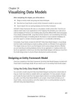
Entity Data Model Designer
The design surface of the Entity Data Model Designer hosts visual representations of enti-
ties and associations. If you have worked with other third-party entity-relationship modeling
tools, the presentation should be familiar. Each entity appears as a collapsible rectangle with
the name of the entity in bold at the top. Below the name is a list of defined entity proper-
ties, followed by any navigation properties.
Entity Name
Properties
Navigation Properties
Associations appear as lines connecting related entities. Although the line does not indicate
which properties are joined by the association, the cardinality (that is, the multiplicity of the
association endpoints) does appear as indicators on either end of the line.
The bottom-right corner of the Designer includes four display controls that let you adjust
the view of the model. From top to bottom, the four controls are: Zoom In, Zoom To 100%,
Dwonloaded from: iDATA.ws
Chapter 14 Visualizing Data Models
231
Zoom Out, and Move Via A Thumbnail View. Right-click on the design surface to see addi-
tional view management options through a shortcut menu.
Zoom In
Zoom to 100%
Zoom Out
Move Via a Thumbnail View
The Designer’s main purpose is to simplify the creation and editing of entities and their asso-
ciations. You perform most of these editing activities by clicking entities, entity properties, or
associations. You then use the Visual Studio Properties panel to modify the various settings
of the selected entity, property, or association. Right-clicking entities, properties, associations,
or even on the design surface provides access to additional editing and model management
features.
A full listing of editing activities is available in the Visual Studio online help. The following list
shows some the main tasks you can accomplish using the Model Designer:
Edit entities To add a new entity, right-click the design surface and select Add | Entity
from the shortcut menu. The Add Entity dialog box that appears lets you specify the
new entity name, its primary key (if any), and any inheritance relationship it has to an
existing entity.
Dwonloaded from: iDATA.ws
232
Microsoft ADO.NET 4 Step by Step
On the design surface, select an existing entity and use the Visual Studio Properties
panel to manage its basic settings. To remove an entity, click that entity in the Designer
and press Delete.
Edit properties To create a new property within an entity, right-click the entity and
select one of the Add | Property choices from the shortcut menu. The Designer supports
three types of properties: scalar properties, which are simple types such as strings and
numbers; navigation properties, which enable natural links between different entities;
and complex properties, a grouping of other simple types based on some conceptual
relationship. Complex types—such as an Address type that contains distinct street, city,
and postal code properties—can be defined independently by right-clicking the design
surface and selecting the Add | Complex Type shortcut command.
Edit associations Add a new association by right-clicking an entity and choosing
Add | Association from the shortcut menu. The Add Association dialog box that appears
lets you define the endpoints of the association, including the multiplicity of each end.
Select an association and use the Visual Studio Properties panel to manage its settings.
(Most of the settings are unavailable if the association is based on a storage layer for-
eign key relationship.) To remove an association, click its line in the Designer and press
Delete.
Dwonloaded from: iDATA.ws