Components of USB
Bạn đang xem bản rút gọn của tài liệu. Xem và tải ngay bản đầy đủ của tài liệu tại đây (77.24 KB, 5 trang )
Components of USB
The foundation for a test approach requires a basic understanding of functional
dependency and relationships. However, the order in which to go about beginning the
actual approach may differ from the order of logical dependency. A tip in starting is
to approach testing USB from a user point of view, keeping in mind the coverage of
the logical and physical integration and cross–dependencies, in order to affirm
completeness in coverage. The information in the following paragraphs encourage
the creation of a simple test approach.
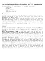
The following diagram shows the USB architecture for an automotive computing
device:
Transfer Types
USB supports the 4 basic transfer types listed below. For more information, see
Further Reference_apctest_Further_Reference.
• Interrupt (Keyboard, Legacy)
• Bulk (CUE®, Vetronix® Box)
• Isochronous (CD Changer)
• Control (All)
Built on Thursday, January 25, 2001
How WCEfA USB is different from Desktop
PCs
The primary differentiating factor between WCEfA USB and Desktop PC USB is the
type of physical connector. Automotive computing devices use the Hiroshi type
connector. In addition to the data and 5 volt power, this connector provides the 12
volts typically found in the car environment.
In the car environment, the USB chain experiences high frequency power cycles from
the root node. To attach a function, use the USBDeviceAttach function in the USB
client driver. To detach a function, use the USB_CLOSE_DEVICE handler of the
USBDeviceNotifications function in the USB client driver.
The following list describes hardware actions and the expected response for each:
• Warm boot – the attach function is called.
• Hot unplug – the detach function is called.
• Hot plug–in – the attach function is called if the device driver is already
registered.
• Ignition Off/Faceplate Detached – nothing is called.
• Unplug and Plug during Ignition Off – nothing is called.
• Ignition On/Faceplate Attached – the USB host controller enumerates all
the USB devices connected. A thread—with the highest priority—will call the
detach function of each loaded device driver, one by one. The same thread will
call the attach function for all the currently connected device drivers, one by
one, if the device driver is registered.
Built on Thursday, January 25, 2001
Send
USB Configurations
A USB network is composed of a master host computer that is connected to slave
USB devices. These devices may have a single function, such as a cell phone, or may
contain a hub connection that allows other USB devices to be chained to them. This
creates a tiered-star architecture that may be expanded to multiple levels. Examples
include the following:
A USB network may support up to 127 devices. This limit is due to the device
address field being limited to 7 bits.
The Auto PC is limited to four tiers and only one hub below the host hub. This
counts the Auto PC as the first tier with three layers below it.
Built on Thursday, January 25, 2001
Send feedback to MSDN. Look here for MSDN Online
USB Connectivity
USB offers a reliable, high-speed alternative to a standard serial port for connecting a
Windows CE-based platform to a desktop computer. Windows CE 2.10 and 2.12,
however, could not support USB connectivity to desktop systems, unless an OEM
implemented that functionality.
Windows CE 3.0 and later, however, do offer connectivity through USB. Windows
CE 3.0 and later provide a USB Function controller driver for Windows CE-based
platforms that include the appropriate USB Function controller hardware. By means
of this driver, the USB Function controller hardware appears to Windows CE as a
virtual serial port. Similarly, the desktop computer must have a similar host-side USB
serial driver. With the Windows CE-based platform and the desktop computer so
configured, the standard serial-port based mechanisms for connectivity can be used
over a USB connection. OEMs can find the files necessary for implementing USB
connectivity in the platform\cepc\drivers\serial_sl11\ directory of their Microsoft
Windows CE Platform Builder installations. These files support the Scanlogic
Corporation’s SL11 USB Function controller chipset. For complete information on
implementing a virtual serial port via USB on a Windows CE-based platform, see
Sample USB Function Controller Driver.
There is, however, still no support for making a Windows CE–based platform itself
appear as a USB peripheral to other host computers. This is because Windows CE
only implements the host side of the USB client/host architecture. That is, the HCD
and USBD modules supplied in Windows CE do not provide facilities to connect a
Windows CE–based platform to a desktop computer that is running as a USB host.
An OEM could implement this functionality if desired, although, as with the above
connectivity scenarios, the Windows CE-based platform would still require USB
Function controller hardware.
Built on Wednesday, October 04, 2000
Send feedback to MSDN. Look here for MSDN Online resources.
USB Connector
The connectors on the reference platforms are the standard 4-pin USB type intended
for the desktop environment and are only used during development and testing.
The Auto PC reference hardware documentation refers to an eight-pin connector
designed by Hirose (part number GT17-8DP-DS) and meant for a car’s high-
vibration and wide-temperature-range environment. The pinout is as follows:
Pin Number Pin Function
1 +5V
2 Data -
3 Data +
4 GND
5 GND
6 Wakeup2
7 Remote Power
8 +12V Main battery
Two wires are used for the USB standard serial data bus. This data bus is shared by
the Auto PC and its USB slave devices. The data rate is typically 12 megabits per
second (Mbps), but there is an optional 1.5 Mbps mode. In accordance to the USB
standard, the data is differentially driven to improve noise immunity.
The USB connector can also supply power to the hubs and devices on the USB
network. While some devices are self-powered from their own power supplies, others
pull power from the USB connector. The Auto PC USB connector supplies two power
sources of +5V and +12V.
The +5V supply is specified by the USB standard and is required to provide a
maximum of 600 mA continuous.
The +12V line is added by the Auto PC design and continuously supplies a
maximum of 3 A.
The Auto PC USB connector also adds two signal lines for use in wakeup modes
(labeled Wakeup2 and Remote Battery). The OEM system designer can use these
signal lines to allow USB peripherals to signal the Power Management System to
trigger a power event. This allows the Auto PC to transition from a powered-down
state to a partial-power state to process information from the USB peripheral; for
example, to store a page message. See the Power Management specification for
more information.
Built on Thursday, January 25, 2001