giáo trình mạng truyền thông công nghệ
Bạn đang xem bản rút gọn của tài liệu. Xem và tải ngay bản đầy đủ của tài liệu tại đây (22.85 MB, 140 trang )
Introduction to industrial
communication networks
Section 1:
Basic concepts
Section 2:
Section 3:
Requirements and positioning of the
mai
The ISO model
Section 4:
Physical media
Section 5:
Major medium access methods
Section 6:
Concepts used at application
level
Interconnection products
Section 7:
n networks
1/160
Introduction to industrial
communication networks
Section 8:
ASi
Section 9:
CANopen
Section 10:
DeviceNet
Section 11:
Modbu
Section 12:
Ethernet - TCP/IP Profibus-DP
Section 13:
FIPIO
s
2/160
Introduction to industrial
communication networks
Section 14:
Interbus
Section 15:
Modbus
Section 16:
Comparison table for the major networks
Section 17:
A look at the IA communication offer
Section 18:
How PL7 deals with the communication
function
3/160
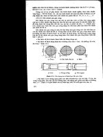
Section 1: Basic concepts
Elements used during communication
Communication
module
Communication
module
Data
Transmission
Medium
Transmission
Data
Reception
Transmitter/Receiv er
Reception
Transmitter/Receiver
The data comprises physical elements (light, sound, images, electrical voltage,
etc.) to which a direction has been attributed.
4/160
Section 1: Basic concepts
Transmission methods
Data can be transmitted in analog format:
Continuous progression of value
Or in digital format:
Discontinuous progression of value (sampling)
5/160
Section 1: Basic concepts
Transmission types
Simplex transmission: Unidirectional
Half duplex transmission: Alternate bidirectional
Full duplex transmission: Simultaneous bidirectional
6/160
Section 1: Basic concepts
Transmission types
■ Serial transmission:
The link usually requires 3 wires: send, receive and earth.
The bits in a byte are transmitted one after the other.
■ Parallel transmission:
The bits in a byte are transmitted simultaneously.
Used for shortdistances. As each channel tends to cause interference on
neighbouring channels, the quality of the signal deteriorates rapidly.
7/160
Section 1: Basic concepts
Serial transmission types
■ Synchronous serial transmission:
Data is transmitted continuously.
A synchronization signal is transmitted in parallel with the data signals.
■ Asynchronous serial transmission:
Data can be transmitted in an irregular fashion, although the interval
between 2 bits is fixed.
Synchronization bits (START, STOP) encapsulate the data.
8/160
Section 1: Basic concepts
Industrial communication networks
For reasons of cost and durability, most communication
networks use
half duplex asynchronous serial di
transmission.
gital
9/160
Section 2: Requirements and positioning of the main
networks
Communication requirements
1 MB
1
minut
e
Level 3
Company
Information system
1s
Level 2
Workshop
Production
management
Supervision
Level 1
Machines
Control system
1 KB
AMOUNT
OF DATA TO BE
TRANSMITTED
REQUIRED
SPEED OF
REACTION
Level 0
1 bit
1 ms
Components
Actuators
Sensors
10/160
Section 2: Requirements and positioning of the main
networks
Main networks and buses
Control of
process
Data networks
(Data Bus)
Local area networks
(Field Bus)
Control of
machine
Y
et
Modbus PlusFIPWA TCP/IP
Profibus-DP
Modbus
FIPIO
CANopen
Fieldbus
Sensor actuator
(Device Bus)
bus
(Sensor Bu s)
DeviceNet
Interbus
Ethernet
TCP/IP
FTPHTTP...
Ethern
Modbus
AS-i
Simple
Sophisticated
11/160
Section 2: Requirements and positioning of the main
networks
Network strategy of the Schneider industrial sector
■ Core networks:
Ethernet TCP/IP & Modbus
Levels 2 and 3: Information and control system (inter-PLC)
to be extended to fieldbus level (level 1)
CANopen
Like an internal device and panel bus (e.g.: Automation Island)
ASi
For the connection of sensors/actuators (level 0)
Modbus RS 485
When Ethernet is not suitable (price, topology, etc.)
12/160
Section 2: Requirements and positioning of the main
networks
Network strategy of the Schneider industrial sector
■ Legacy networks
FIPIO, Modbus Plus, Uni-Telway, Seriplex
■ Connectivity networks
A pragmatic approach when the market imposes a solution
DeviceNet (Allen-Bradley) - Profibus (Siemens) - Interbus Phoenix) etc.
(
13/160
Chapter 3: The ISO model
ISO model
ISO = International Organization for Standardization
STATION
Modbus or
Unite...
Network
concept
Example:
TCP/IP
Bus
concept
APPLICATION 7
LAYER
Network administration (starting and stopping the
network, message handling)
PRESENTAT ION
6 LAYER
Entity used for PC/MAC dialogue
4
SESSION
5
LAY
the network
TRANSPORT
4 LAYER
Organize and synchronize the exchang ER
es between users of
End-to-end checking: restart on errors which have been
signalled or otherwise by the network layer
NETWORK
LAYER
3
3
Switching in a mesh network: establishment of route
LINK
LAYER
2
Sub-layer: error correction, acknowledgement
Sub-layer: management of access to physical medium
PHYSICAL
LAYER
1
TCP: Transmission Control Protocol (Layer 4)
Twisted pair, shielded twisted pair, coaxial cable, optical
fibre...
IP: Internet Protocol (Layer 3)
14/160
Chapter 3: The ISO model
Examples of frames in relation to the ISO model
Modbus RTU frame
Request to read words W5 and W6 at slave address 7
1
Bytes
1
Slave
2
Function
address
=7
No. of first
code
=3
2
2
No. of words
word
=5
to be read
=2
CRC 16
Ethernet TCP-IP frame
Bytes
8
6
6
46 to 1500
20 20
Source
Application
FTP, HTTP , SMTP Modbus etc.
4
FCS
TCP
IP
LLC
addr.
layers
addr.
Preamble
Destin.
2
15/160
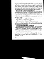
Chapter 4: Physical media
Physical media
Most popular transmission media
A few electrical standards for twisted pairs
The various topologies
16/160
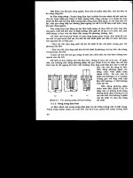
Chapter 4: Physical media
Most popular transmission media
The MEDIA establish the transmission quality:
• speed
• distance
• electromagnetic immunity
Cost of
medium
Low
Most commonly used media:
Pair of twisted wires
The simplest to install, and the least expensive.
Coaxial cable
This consists of a copper conductor, surrounded by grounding shielding. There is a plastic insulating layer
between the conductor and the shielding. The coaxial cable has excellent electrical properties and is
suitable for high speed transmission.
Optical fibre
Electrical signals are not carried by a copper cable, but an optical fibre transmits light signals.
This is suitable for use in harsh industrial environments. Transmission is reliable over long distances.
High
17/160
Chapter 4: Physical media
A few electrical standards for twisted pairs
RS232:
Point-to-point link via 25-pin SUB-D connector.
Distance < 15 meters, speed < 20 Kbps.
RS422A:
Full duplex (simultaneous bidirectional) multi-drop bus on 4 wires.
2 transmission wires, 2 reception wires.
Good immunity to interference. Max distance 1200 meters at 100
Kbps.
istics as RS422A but on 2 wires.
RS485:
Same character
Half duplex (alternate bidirectional) multi-drop bus on 2 wires.
18/160
Chapter 4: Physical media
The various topologies
POINT-TO-POINT TOPOLOGY
STAR TOPOLOGY
(Between 2 units
in communication)
GRID TOPOLOGY
(Devices are linked to one
another, forming a “spider’s
web”.
There are a number of
possible paths for reaching
a node)
(Several units
communicating via
their own line line
with a Central unit)
RING TOPOLOGY
(A
ll the units are connected in
series in a closed loop.
Communications must pass
via all the units to arrive at the
receiver)
TREE TOPOLOGY
(This is a variant of
the star topology)
BUS TOPOLOGY
(The network consists of a main
line to which all the units are
connected)
19/160
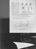
Section 5: The main medium access methods
The main medium access
methods
Master - Slave
Token ring
Random access
20/160
Section 5: The main medium access methods
Master - Slave
Located at the link layer level
The MASTER is the entity which grants access to the medium.
The SLAVE is the entity which accesses the medium after requesting it from the master.
Polling
What do you want to say?
Nothing to declare
MASTER
Response
SLAVE
Eg: Profibus-DP
21/160
Section 5: The main medium access methods
Token ring
Located at the link layer level
The members of a logical RING gain access to the network upon receipt of a token.
The TOKEN is a group of bits that is passed in a rotating address sequence from one
node to another.
Address 2
Address 3
Address 1
Eg: Modbus Plus
Address 4
22/160
23/160
Section 5: The main medium access methods
Random access
Located at the link layer level
Carrier Sense Multiple Access
A set of rules determining how network devices respond when two devices attempt to
use the medium simultaneously (called a collision).
CSMA/CD is a type of contention protocol: competition for resources
Informal discussion between
undisciplined individuals:
As soon as there’s a
silence,
the
one who wants t o talk
begins to speak.
Address 2
Address 3
Address 1
Address 4
23/160
Section 5: The main medium access methods
CSMA/CD
CSMA/CA
CSMA/CD = Carrier Sense Multiple Access Collision Detect: Destructive collision
1 - Collision detection
2 - Stop of the emitted frame
3 - Scrambling frame emission
ime
Ethernet
Eg:
4 - Wait a random t
5 - Frame re-emission
CSMA/CD = Carrier Sense Multiple Access Collision Avoidance: Non destructive
2 - The device with the lower priority stops its transmission
1 - Non destructive collision detection
Eg
3 - End of the high priority
frame transmission
collision
: CAN
4 - The device with lower priority can send its frame
24/160
Section 6: Concepts used at application level
Concepts used at
application level
Client - Server
Producer - Consumer
Traffic types
The concept of a profile
25/160