draft ietf dmm deployment models 00
Bạn đang xem bản rút gọn của tài liệu. Xem và tải ngay bản đầy đủ của tài liệu tại đây (279.88 KB, 20 trang )
DMM Deployment Models and
Architectural Considerations
Internet-Draft
DMM WG,
Expires: February 23, 2017
S. Jeon, Sungkyunkwan University; S. Gundavelli, Cisco
Presenter: Harry 2.16.2017
Abstract
• This document identifies the deployment models for Distributed Mobility Management architecture.
• One of the key aspects of the Distributed Mobility Management (DMM) architecture is the separation of control plane
(CP) and data plane (DP) functions of a network element.
• While data plane elements continue to reside on customized networking hardware, the control plane resides as a
software element in the cloud.
• This is usually referred to as CP-DP separation and is the basis for the IETF’s DMM Architecture.
• This approach of centralized control plane and distributed data plane allows elastic scaling of control plane and efficient
use of common data plane that is agnostic to access architectures.
Terminology
• Home Control-Plane Anchor (H-CPA)
• The Home-CPA function hosts the mobile node’s mobility session.
• There can be more than one mobility session for a mobile node [MN] and those sessions may be anchored on the same or
different Home- CPA’s.
• The home-CPA will interface with the home-dpa for managing the forwarding state.
• Home Data Plane Anchor (Home-DPA)
• The Home-DPA is the topological anchor for the mobile node’s IP address/prefix(es).
• The Home-DPA is chosen by the Home-CPA on a session-basis.
• The Home-DPA is in the forwarding path for all the mobile node’s IP traffic.
Terminology
• Access Control Plane Node (Access-CPN)
• The Access-CPN is responsible for interfacing with the mobile node’s Home-CPA and with the Access-DPN.
• The Access-CPN has a protocol interface to the Home-CPA.
• Access Data Plane Node (Access-DPN)
• The Access-DPN function is hosted on the first-hop router where the mobile node is attached.
• This function is not hosted on a layer-2 bridging device such as a eNode(B) or Access Point.
DMM Architectural Overview
• Following are the key goals of the Distributed Mobility Management architecture.
• 1. Separation of control and data Plane
• 2. Aggregation of control plane for elastic scaling
• 3. Distribution of the data plane for efficient network usage
• 4. Elimination of mobility state from the data plane
• 5. Dynamic selection of control and data plane nodes
• 6. Enabling the mobile node with network properties
• 7. Relocation of anchor functions for efficient network usage
DMM Service Primitives
• The functions in the DMM architecture support a set of service primitives.
• Each of these service primitives identifies a specific service capability with the exact service definition.
• The functions in the DMM architecture are required to support a specific set of service primitives that are mandatory for
that service function.
• Not all service primitives are applicable to all DMM functions.
• The below table identifies the service primitives that each of the DMM function SHOULD support.
• The marking "X" indicates the service primitive on that row needs to be supported by the identified DMM function on the
corresponding column; for example, the IP address management must be supported by Home-CPA function.
Figure 1: Mapping of DMM functions
DMM Functions and Interfaces
Home Control-Plane Anchor (H-CPA):
• The Home-CPA function hosts the mobile node’s mobility session.
• There can be more than one mobility session for a mobile node and those sessions may be anchored on the same or
different Home-CPA’s.
• The home-CPA will interface with the homd-dpa for managing the forwarding state.
• There can be more than one Home-CPA serving the same mobile node at a given point of time, each hosting a different
control plane session.
DMM Functions and Interfaces
Home Control-Plane Anchor (H-CPA):
• The Home-CPA is responsible for life cycle management of the session, interfacing with the policy infrastructure, policy
control and interfacing with the Home-DPA functions.
• The Home-CPA function typically stays on the same node. In some special use-cases (Ex: Geo-Redundancy), the session
may be migrated to a different node and with the new node assuming the Home-CPA role for that session.
Home Data-Plane Anchor (H-DPA):
• The Home-DPA is the topological anchor for the mobile node’s IP address/prefix(es).
• The Home-DPA is chosen by the Home-CPA/MC on a session-basis.
• The Home-DPA is in the forwarding path for all the mobile node’s IP traffic.
• As the mobile node roams in the mobile network, the mobile node’s access-DPN may change, however, the Home-DPA
does not change, unless the session is migrated to a new node.
• The Home-DPA interfaces with the Home-CPA/MC for all IP forwarding and QoS rules enforcement.
• The Home-DPA and the Access-DPN functions may be collocated on the same node.
Access Control Plane Node (Access-CPN)
• The Access-CPN is responsible for interfacing with the mobile node’s Home-CPA and with the Access-DPN.
• The Access-CPN has a protocol interface to the Home-CPA.
• The Access-CPN is responsible for the mobile node’s Home-CPA selection based on: Mobile Node’s Attach Preferences,
Access and Subscription Policy, Topological Proximity and Other Considerations.
• The Access-CPN function is responsible for MN’s service authorization.
• It will interface with the access network authorization functions.
Access Data Plane Node (Access-DPN)
• The Access-DPN function is hosted on the first-hop router where the mobile node is attached.
• This function is not hosted on a layer-2 bridging device such as a eNode(B) or Access Point.
• The Access-DPA will have a protocol interface to the Access-CPA.
• The Access-DPN and the Home-DPA functions may be collocated on the same node.
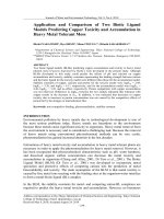
DMM Function Mapping to other Architectures
• Following table identifies the potential mapping of DMM functions to protocol functions in other system architectures
Protocol for Forwarding Policy Configuration (FPC) in
DMM
•
The specification as per this document supports the separation of the Control-Plane for mobility- and
session management from the actual Data-Plane.
•
The protocol semantics abstract from the actual details for the configuration of Data-Plane nodes and
apply between a Client function, which is used by an application of the mobility Control- Plane, and an
Agent function, which is associated with the configuration of Data-Plane nodes according to the policies
issued by the mobility Control-Plane.
•
The scope of the policies comprises forwarding rules and treatment of packets in terms of encapsulation, IP
address re-writing and QoS.
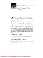
Deployment Models
• Model-1: Split Home Anchor Mode
• In this model, the control and the data plane functions of the home anchor
are separated and deployed on different nodes.
• The CP function of the Home anchor is handled by the Home-CPA and
where as the data plane function is handled by the Home-DPA.
• In this model, the access node operates in the legacy mode with the
integrated control and user plane functions.
• The FPC interface defined in [I-D.ietf-dmm-fpc-cpdp] allows the CP
functions to interact with the data plane for the subscriber’s forwarding
state management.
Figure 3: Split Home Anchor Mode
Deployment Models
• Model-2: Seperated Control and User Plane Mode
• In this model, the control and the data plane functions on both the home
anchor and the access node are seperated and deployed on different nodes.
• The CP function of the Home anchor is handled by the Home-CPA and
where as the data plane function is handled by the Home-DPA.
• The CP function of the access node is handled by the Access-CPN and where
as the data plane function is handled by the Access-DPN.
• The FPC interface defined in [I-D.ietf-dmm-fpc-cpdp] allows the CP functions
of the home and access nodes to interact with the respective data plane
functions for the subscriber’s forwarding state management.
Figure 4: Seperated Control and User Plane Mode
Deployment Models
• Model-3: Centralized Control Plane Mode
• In this model, the control-plane functions of the home and the
access nodes are collapsed.
• This is a flat architecture with no signaling protocol between the
access node and home anchors.
• The interface between the Home-CPA and the Access-DPN is
internal to the system.
• The FPC interface defined in [I-D.ietf-dmm-fpc-cpdp] allows the
mobility controller to interact with the respective data plane
functions for the subscriber’s forwarding state management.
Figure 5: Centralized Control Plane Mode
Deployment Models
• Model-4: Data Plane Abstraction Mode
• In this model, the data plane network is completely abstracted from the
control plane.
• There is a new network element, Routing Controller which abstracts the
entire data plane network and offers data plane services to the CP
functions.
• The CP functions, Home-CPA and the Access-CPN interface with the Routing
Controller for the forwarding state management.
• The FPC interface defined in [I-D.ietf-dmm-fpc-cpdp] allows the Home- CPA
and Access-CPN functions to interface with the Routing Controller for
subscriber’s forwarding state management.
Figure 6: Data Plane Abstraction Mode
Deployment Models
• Model 5: On-Demand Control Plane Orchestration Mode
• In this model, there is a new function Mobility Controller
which manages the orchestration of Access-CPN and HomeCPA functions.
• The Mobility Controller allocates the Home-CPA and AccessDPN