Tài liệu SERVO MOTOR LG
Bạn đang xem bản rút gọn của tài liệu. Xem và tải ngay bản đầy đủ của tài liệu tại đây (4.65 MB, 294 trang )
Instruction Manual
Manual Version : [ver 3.4]
Software Version : Higher than 2.14
The first edition :
2002. 01. 02.
A revised edition : 2004. 11. 01.
- This content and specifications may be changed without prior notice
according to Software Version.
- No part of this may be reproduced in any form or by any electronic or
mechanical means without permission of Metronix.
- Metronix holds the patent right, the trademark right, the copyright and
intellectual property rights which are related to this product. Therefore NO
permission to illegal use.
Thank you for purchasing Metronix’s
Metronix s AnyPack Series
Read this instruction
instruction manual thoroughly before installation, operation, maintenance or
inspection of this product.
Symbols for Safe Operation
In this manual, NOTES FOR SAFE OPERATION are classified as “WARNING” or
“CAUTION”.
WARNING
Indicates a potentially hazardous situation which, if not avoided, could result in death or
serious injury to personnel.
CAUTION
Indicates a potentially hazardous situation which, may result in minor or moderate injury
to personnel, and possible damage to equipment if not avoided. It may also be used to
alert against unsafe practices.
Items described in Caution may also result in a vital accident in some situations.
In cither case, follow these important notes.
Note for Safe Operation
INSTALLATION
CAUTION
Make sure to keep the install direction.
Do not throw down and prevent from impact.
Never use the equipment where it may be exposed to splashes of water,
corrosive or flammable gases, or near flammable materials.(Failure to
observe this warning may lead to electric shock or fire)
WIRING
For the input power supply of Servo drive, surely use AC200~230[V]
Make sure to ground the ground terminal.
Never connect the AC main circuit power supply to servo motor.
Never connect the AC main circuit power supply to output terminals U,V and W.
Use the compression terminal with insulated tube when wire the power
terminal.
Make sure that Power cable(U,V,W) and Encoder cable are separated when
connected.
Disconnect the power wires surely after the input power is off and
“CHARGE” Lamp is completely OFF.
Surely use Twist pair shield cable for pulse command signal (PF+, PF-,
PR+, PR-), speed command signal(SPDCOM), torque limit signal(TRQLIM).
OPERATION
Before starting operation, check and adjust each menu.
During operation, do not touch the shaft of motor.
During operation, do not touch the heat sink.
Do not connect or disconnect CN1,CN2,CN3 connectors while power is
applied to the circuit.
GENERAL PRECAUTIONS
Specifications are subject to change for product modifications and
improvements. In this case, we issue the manual on updated Version NO.
Precaution at First Setup
CAUTION
Make sure the Power Supply voltage (AC200~230[V]) and wiring before
power is applied to the circuit.
At first power apply, applied the power on Servo-OFF status.
Verify the model No. of motor and the No. of Encoder pulse before power is
applied to the circuit.
Set the motor ID on menu[PE-201], number of Encoder Pulse on menu [PE-204]
After finishing the above, set the operation mode of servo drive by linking
upper motion controller on the menu [PE-601].
Wire CN1 if servo drive according to each operation mode referring to “1.2 System
Construction”(Refer to “5.5 Example of connecting to upper Controller”)
The ON/OFF state of each CN1 input contacts can be verified at CN1
contacts state.
MAINTENANCE AND INSPECTION
WARNNING
After turning OFF Control power supply L1C, L2C, and main power supply
L1, L2, L3 then wait enough time (Until the charge lamp is turned off),
Proceed the maintenance and inspection. High voltage still remains in the
internal condenser.
Never touch the high-voltage terminals at first power apply.
Do not repair, inspect, and replace the component except for authorized
person.
The alteration of products is not allowed in any case
Contents
◈ Precaution
1. Product Configuration and Main Function
1.1 Product Configuration
1.1.1 Checking Products……………………………………………. 1-2
1.1.2 Identifying…….……………………………………………….. 1-4
1.2 System Composition
Composition
1.2.1 Summary……………………………………………………….. 1-9
1.2.2 Position Operation Mode……………………………………… 1-11
1.2.3 Speed Operation Mode….……………………………………
1-12
1.2.4 Torque Operation Mode………………………………………
1-13
1.2.5 Speed/Position Operation Mode……………………………. 1-14
1.2.6 Speed/Torque Operation Mode…………………………….. 1-15
1.2.7 Position/Torque Operation Mode………………………….
1.3 Signal Explanation……………………………………………..
1-16
1-17
2. Installation
2.1 Servo Motor
2.1.1 Operating Environment…………………………………………
2-2
2.1.2 Preventing Excessive Impact………………………………… 2-2
2.1.3 Wring …………………………………………………………… 2-2
2.1.4 Assembling Load System………………………………………
2.1.5 Cable Installation………………………………………………. 2-3
2.2 Servo
Servo Drive
2.2.1 Operating Environment……………………………………… 2-4
2.2.2 Installation In a Control Board(Panel)……………………
2-5
2.2.3 Wring………………………………………………………….
2-6
2-3
3.Wiring
3.1 Internal Block Diagram
3.1.1 Block Diagram (Rated Output is less than 400[V])………. 3-2
3.1.2 Block Diagram (Rated Output is from 0.5 to 11.0[kW])
3-3
3.2 Power Board Wring
3.2.1 Wiring Diagram (Rated Output is less than 400[V])………
3-4
3.2.2 Wiring Diagram (Rated Output is from 0.5 to 11.0[kW]).. 3-5
3-5
3.2.3 Power Board Part Specification……………………………..
3.3 Timing Diagram
3.3.1 Timing Diagram at Supplying Power.………………………
3.3.2 Timing Diagram at Alarm …………………..……………….
3-6
3-7
3.4 Wiring control Signal
Signal
3.4.1 Contact Input Signal.…………………………………………
3-8
3.4.2 Contact Output Signal ……….……………………….…..…
3-8
3.4.3 Analog I/O Signal
…………………………………………
3.4.4 Pulse Input Signal
…………………………………………..
3.4.5 Encoder Output Signal………………………………………
3-9
3-11
3-11
3.5 Incremental Encoder Signal (CN2) Wiring
3.5.1 Small-size Motor…………………………………………….
3-12
3.5.2 Medium/Large-size Motor………………………………….
3-12
3.6 Absolute Encoder Signal (CN2)
(CN2) Wiring
3.6.1 Small-size Motor.…………………………………….………
3-13
3.6.2 Medium/Large-size Motor……………………………….…
3-13
3.6.3 How to use Absolute Encoder…………………………….
3-14
3.7 Communication (Option) Signal Wiring
3.7.1 PC-Communication (for RS232C)……………………….
3-16
3.7.2 Communication for Only Servo (for O/S Download)
3-17
4.Detail Explanation of Program Menu
4.1 How to Operate Loader……………………….………….……. 4-2
4.2 Program Menu Summary.…………….………….……………. 4-4
4.3 Display Operation
Operation state
4.3.1 Display State………………………………….………………… 4-18
4.3.2 Display Speed…….……………………………….…………… 4-18
4.3.3 Display Position……………………….………………………
4-18
4.3.4 Display torque and Load …………………………………….. 4-18
4.3.5 Display I/O State………………………………………………
4-19
4.3.6 Display Software Version……………………………………. 4-20
4.4 Setting Up Menu
4.4.1 Setting System Variables …………………………………....
4-21
4.4.2 Setting Control Variables.…………………………………....
4-25
4.4.3 Setting Analog I/O Variables …..……………………………
4-30
4.4.4 Setting I/O Connecting Variables………………………….
4-32
4.4.5 Setting Speed Operation Variables…………………………..
4-36
4.4.6 Setting Position Operation Variables………………………..
4-38
5. Handling and Operation
5.1 Check Point before Operation……………………………….
5.2 Handling
5-2
5.2.1 Alarm Reset....………………………………………….……… 5-3
5.2.2 Alarm History Clear……………………………………..……. 5-3
5.2.3 Menu lnitialization……………………………………………… 5-3
5.2.4 Prohibiting Menu Handling…………………………………… 5-3
5.2.5 Absolute Encoder Reset………………………………………. 5-3
5.2.6 Setting Input Contact Logic…………………………. ….…. 5-4
5.2.7 Compulsory Handing Input Contact…………………………. 5-5
5.3 Adjustment
5.3.1 Gain Tuning …………………………………………….………. 5-6
5.3.2 Current Offset Tuning…………………………………………..
5-6
5.4 Adjustment
5.4.1 Gain Tuning
………….………………………………….. 5-7
5.4.2 Current Offset Tuning..……………………………………….
5.4.3 Operation at Z position……………….………………………. 5-7
5.5 Example of Connecting to Upper Controller…………….. 5-8
5-7
6.Communication Protocol
6.1 The outline and Specification of Protocol
6.1.1 Outline …………………….……..…..……………………
6-2
6.1.2. The Specification of Protocol
and Cable Connecting diagram ……………………..
6-3
6.2 Basic Structure of Communication Protocol
6.2.1 Frame Type
………..……………………………….
6.2.2 The Collection of Commands ………………………………
6-4
6-6
6.3 Commands for Data Processing
6.3.1 Data Reading Command[RSS/RSB] ……..……..…… 6-7
6.3.2 Data Writing Command[WSS/WSB] ..…………………
6-16
6.3.3 Monitor Command[X##/Y##/Z##]..………………… 6-22
6.3.4 Set Command[WDK] ……….…………………..……….
6-31
6.3.5 Check Command[RCS/ RCB]……………………………
6-34
6.4 Commands for Operation
Operation
6.4.1 Speed Operation Command[CJR] ……………………
6-40
6.4.2 Position Operation Command[CPR]…..………………
6-43
6.4.3 Program Operation Command[CTA]……………………
6-46
6.4.4 Operation Command[CST/CSM/CSH/COR/CGR]……
6-49
7. Product Specification
7.1 Servo Motor
7.1.1 Features …………………………………………….………..
7-2
7.1.2 External Dimensions………………………………….……..
7-13
7.2 Servo Drive
7.2.1 Features ………………………………………………….…..
7-23
7.2.2 External Dimensions…………………………………………
7-24
7.3 Option and Perpherals……………………….…………………. 7-28
8. Maintenance
Maintenance and Inspection
8.1 Maintenance and Inspection
…....………………………………………………..
8-2
8.1.2 Inspection Items………………………………………………
8.1.1 Caution
8-3
8.1.3 Period of Replacing Parts…………………………………… 8-4
8.2 Fault Diagnosis and Corrective Actions
8.2.1 Servo Motor …....……………………………………………… 8-5
8.2.2 Servo Drive
………………………………………………. 8-6
[Appendix]
Appendix 1 summary Program Menu………………..……
………
appendix 1-1
Appendix 2 Test operation ….………………………..……………. appendix 2-1
Appendix 3 Regenerative braking………………………..………… appendix 3-1
* Guarantee Letter
* Revision History
Chapter1
Product Configuration and Main Function
1.1 Product Configuration
1.1.1 Checking Products …………………….…………… 1-2
1.1.2 Identifying the Parts ……………………….……… 1-4
1.2 System Composition
Composition
1.2.1
1.2.2
1.2.3
1.2.4
Summary …………..………………………………
Position Operation Mode ……………………..…
Speed Operation Mode……………………………
Torque Operation Mode……………………………
1-9
1-11
1-12
1-13
1.2.5 Speed/Position Operation Mode ………………..
1.2.6 Speed/Torque Operation Mode …….……………
1.2.7 Position/Torque Operation Mode ..……………..
1-14
1-15
1-16
1.3 Signal Explanation
……………………………….
1-17
APDAPD-VS[Standard Type] Manual
1.1 Product
Product Construction
1.1.1 Checking Products
① Check if the products are the right one you ordered.
- Check the types marked in the nameplates of Servo Drive
- Check the types marked in the nameplates of Servo Motor
② Check Product and Option Items.
- Check if the cable types and length are right.
- Check if the regenerative resistance is in accordance with the standard.
- Check if the motor shaft is correct.
- Check if the Oil Seal and Brake is correct.
- Check if the reducer/gearbox and reduction ratio is correct.
- Check if the Encoder type is correct.
③ Check the External Appearance
- Check if there is no dust or moisture
- Check if there is fading, contamination, damage, and disconnection
- Check if the tightness of fitting & bolts are correct.
- Check if there is no noise or excessive friction at rotating
■ Servo drive Type Designation
APD
VS
–
Type
AnyPack Series
Servo Drive
VS
:
Standard
type
VP : ControllerEmbedded
type
1-2
04
Drive Capacity
R5 : 50W
15 : 1.5kW
01 : 100W
20 : 2.0kW
02 : 200W
35 : 3.5kW
04 : 400W
50 : 5.0kW
05 : 500W
75 : 7.5kW
10 : 1.0kW 110: 11.0Kw
15 : 1.5kw 150 : 15.0kW
N
A4
Encoder Type
Exclusiv
N : Incremental
e
A : Absolute
Option
Code
Chapter1 Product Configuration
Configuration and Main Function
■ Servo Motor Product Type
APM – S B 04 A E K 1 G1 03
AnyPack Series
Servo Motor
Motor Shape Type
S : 실축형
H : 중공축형
B : 조립형
Motor Capacity
R3 : 30[W]
Shape of Shaft
Reduction ratio
R5 : 50[W]
N : Straight
01 : 100[W]
03 : 1/3
K : One side round
02 : 200[W]
10 : 1/10
(Standard)
03 : 300[W]
04 : 400[W]
05 : 450[W]
06 : 550/600[W]
07 : 650[W]
08 : 750/800[W]
··
·
C : C Cut
D : D Cut
T : Taper shape
R : Both side round
H : Hollow Shaft
Reducer
None : No Reducer
G1
(Flange Mount)
150 :15.0[kW]
Encoder Type
A : Inc. 1024
Rated Speed
A : 3000 [rpm]
F : 180 Flange
D : 2000 [rpm]
G : 220 Flange
G
:
[rpm]
General
G2 : General industry
10 : 1.0[kW]
··
·
For
(Foot Mount)
09 : 850/900[W]
Flange Size
A : 40 Flange
B : 60 Flange
C : 80 Flange
D : 100 Flange
E : 130 Flange
:
industry
1500
Oil Seal, Brake
[P/R]
None : none
B : Inc. 2000
1 : Oil Seal
[P/R]
C : Inc. 2048
2 : Brake
3 : Oil Seal, Brake
[P/R]
D : Inc. 2500
[P/R]
E : Inc. 3000 [P/R]
F : Inc. 5000 [P/R]
G : Inc. 6000 [P/R]
1-3
APDAPD-VS[Standard Type] Manual
1.1.2 Identifying the Parts
■ Servo Motor
- Less than 80 Flange
Motor Power
Cable
Motor
Connector
Encoder
Connector
Encoder
Cable
Shaft
Bearing Cap
Flange
Frame
Housing
Encoder
Cover
- More than 130 Flange
Motor
Connector
Encoder
Connector
Encoder
Cover
Shaft
Bearing Cap
1-4
Flange
Frame
Housing
Chapter1 Product Configuration
Configuration and Main Function
■ Servo Drive
- Small Capacity (less than APD-VS04)
Display
Heat Sink
Operation key
(Left,
Right,
Up,
Main Power Connector
(L1, L2, L3)
Regenerative Resistance
Connector (B1, B2, B3)
- Additional Resistance
- Internal Resistance
CN3 : Communication
Connector
CN2 : Encoder
Connector
Motor Cable
Connector
(U, V, W)
CN1 : Control Signal
Connector
Grounding Connector
(E x2)
Front cover
1-5
APDAPD-VS[Standard Type] Manual
- Medium Capacity (APD-VS05 ~10)
Display
Heat Sink
Main
Operation key
(Left,
Right,
Up,
CN3 : Communication
Connector
Power
Connector
Control Power
Connector
(L1C, L2C)
Regenerative
Resistance
CN2 : Encoder
Connector
CN1 : Control Signal
Connector
Motor Cable
Connector
(U, V, W)
Front cover
Ground
1-6
Chapter1 Product Configuration
Configuration and Main Function
- Large Capacity (APD-VS15 ~75)
Display
Operation key
(Left, Right, Up,
Heat Sink
Main
Power
Connector
Control Power
Connector
(L1C, L2C)
Enter)
CN3:
Communication
Connector
CN2 : Encoder
Connector
CN1
Signal
:
Control
Regenerative
Resistance
Front cover
Motor Cable
Connector
(U, V, W)
Ground
1-7
APDAPD-VS[Standard Type] Manual
- Special Large Capacity (APD-VS110/VS150)
Displa
Operation key
CN3:
Communication
Connector
CN2 : Encoder
Connector
CN1 :
Control Signal
Connector
Control Power
Connector
(L1C, L2C)
L1C L2C
L1
Main Power
1-8
L2
L3
B1
B2
Regenerative
Connector
Resistance
(L1,L2,L3)
(Option)
U
V
W
FG
FG
Motor Cable
Connector
(U, V, W)
Ground
Chapter1 Product Configuration
Configuration and Main Function
1.2 System Composition
Composition
1.2.1 Summary
Servo System can be variously used as per the interface with Upper controller.
1) Position Operation System
Operate Servo by pulse command that operates the position of servo motor by
ration of encoder pulse compared to command pulse.
Upper Controller
Position
Controlle
r
Speed
Controller
Servo Drive
Position
Command
Pulse
Conversion
Servo Motor
Pulse
command
Position
Controlle
r
Speed
Controlle
r
M
Current
Controlle
r
E
Strength : Because of pulse input by transfer unit, upper controller is simple.
Weakness : High speed rotating is difficult at using precise transfer unit
Response characteristics are not good by using various steps of
controller.
2) Speed Operation System
Operating servo by speed command that is analog or digital speed command.
Upper Controller
Position
Controlle
r
Speed
Controller
Position
Command
Pulse
conversion
Servo Drive
Speed
command
Speed
Controlle
r
Current
Controlle
r
Servo Motor
M
E
Strong point : Response of servo is fast.
Easy to control precisely
Weak point : Upper controller is complicate.
1-9
APDAPD-VS[Standard Type] Manual
3) Torque Operation System
Operating Servo by torque command that is analog voltage.
Upper Controller
Strength
Torque
Command
conversion
Torque
Controller
Position
Controlle
r
Servo Drive
Torque
command
Speed
Controlle
r
Current
Controlle
r
: Response of servo is fast.
Easy to control precisely
Weakness : Upper controller is complicate
4) Operation mode
According to interface with upper controller, Operating mode is as below
Operation Mode
System
0
Operating Torque mode
1
Operating Speed mode
2
Operating Position mode
3
Operating Speed/Position mode by selecting connector
4
Operating Speed/Torque mode by selecting connector
5
Operating Position/Torque mode by selecting connector
* Operation mode is set up on menu [PE-601]
1-10
Servo Motor
M
E
Chaper1 Product Configuration and Main Function
1.2.2 Position Operating Mode
Regenerative resistance
MC1
MCCB1
Power supply AC
200-230 [V]
50/60 [Hz]
B1
L1
L2
L3
L1C
L2C
NF
(Note1)
CN2
Servo drive
U
V
W
Input
+24V
IN
U
V
W
E
Output
CN3
DC24V
B2
CN1
38
ALARM+
39
ALARM-
40
RDY+
41
RDY-
42
TLOUT
43
ZSPD
44
BRAKE
45
INPOS
24
GND24
25
GND24
PCON
13
GAIN2
14
PCLEAR
15
TLIMIT
16
ALMRST
17
EMG
18
CWLIM
19
CCWLIM
20
EGEAR2
22
EGEAR1
23
28 MONIT1
SVON
47
29 MONIT2
MONITOR Output
-5V ~+5V
-5V ~+5V
37 GND
PULCOM
Line driver
driver
PF+
PF-
Upper
controller
PR+
PR-
9
10
11
12
Open
collector
Torque
limit
ENCODER Output
49
0V ~+10V
TRQLIM
1
GND
8
32
AO
33
/AO
30
BO
Upper
31
/BO
controller
4
ZO
5
/ZO
3
OPCZO
36
GND
Connect to Case of connector
Note1) The models that are higher than VS05 have a control power terminal(L1C,
L2C)
Note2) Surely use Twist pair shield cable for pulse command signal (PF+, PF-, PR+,
1-11
APDAPD-VS[Standard Type] Manual
PR-) and torque limit signal(TRQLIM).
1.2.3 Speed Operation Mode
Regenerative resistance
MC1
MCCB1
Power supply AC
200-230 [V]
50/60 [Hz]
B1
L1
L2
L3
L1C
L2C
NF
(Note1)
CN2
Servo drive
U
V
W
DC24V
+24V IN
50
PCON
13
GAIN2
14
TLIMIT
16
ALMRST
17
EMG
CWLIM
18
CCWLIM
SPD3
20
21
SPD2
22
19
SPD1
23
DIR
46
SVON
47
STOP
48
U
V
W
E
Output
CN3
Input
B2
CN1
38
ALARM+
39
ALARM-
40
RDY+
41
RDY-
42
TLOUT
43
ZSPD
44
BRAKE
45
INSPD
24
GND24
25
GND24
MONITOR Output
-5V ~+5V
28 MONIT1
29 MONIT2
-5V ~+5V
37 GND
ENCODER Output
Speed
command
Torque
limit
-10V ~+10V
SPDCOM 27
0V ~+10V
GND
8
TRQLIM
1
GND
8
32
AO
33
/AO
30
BO
Upper
31
/BO
controller
4
ZO
5
/ZO
3
OPCZO
36
GND
Connect to Case of connector
Note1) The models that are higher than VS05 have a control power terminal(L1C,
1-12
Chaper1 Product Configuration and Main Function
L2C)
Note2) Surely use Twist Pair shield cable for SPDCOM, TRQLIM, GND.
1.2.4 Torque Control Mode
Regenerative resistance
MC1
MCCB1
Power supply AC
200-230 [V]
50/60 [Hz]
B1
L1
L2
L3
L1C
L2C
NF
(Note1)
CN3
Input
DC24V
+24V
IN
ALMRST
17
EMG
CWLIM
18
CCWLIM
20
19
B2
CN2
Servo drive
U
V
W
CN1
U
V
W
E
Output
38
ALARM+
39
ALARM-
40
RDY+
41
RDY-
42
TCONT
43
ZSPD
44
BRAKE
45
INSPD
24
GND24
25
GND24
MONITOR Output
SPD2
22
SPD1
23
SVON
47
STOP
48
-5V ~+5V
28 MONIT1
29 MONIT2
-5V ~+5V
37 GND
ENCODER Output
Speed
limit
Torque
command
0V ~+10V
-10V ~+10V
32
AO
33
/AO
30
BO
Upper
31
/BO
controller
4
ZO
5
/ZO
SPDLIM
27
3
OPCZO
GND
8
36
GND
TRQCOM
1
GND
8
Connect to Case of connector
1-13
APDAPD-VS[Standard Type] Manual
Note1) The models that are higher than VS05 have a control power terminal(L1C,
L2C)
Note2) Surely use Twist Pair shield cable for SPDCOM, TRQLIM, GND.
1.2.5 Speed/Position
Speed/Position Operation Mode
Regenerative resistance
MC1
MCCB1
Power supply AC
200-230 [V]
50/60 [Hz]
B1
NF
(Note1)
Servo drive
U
V
W
Input
+24V
13
GAIN2
14
PCLEAR
15
TLIMIT
16
ALMRST
EMG
17
CWLIM
19
CCWLIM
MODE
20
21
SPD2/EGR2
22
SPD1/EGR1
23
18
DIR
46
SVON
47
STOP
48
PULCOM
49
Line driver
driver
Upper
controller
Torque
limit
0V ~+10V
39
ALARM-
40
RDY+
41
RDY-
42
TLOUT
43
ZSPD
44
BRAKE
45
INSPD/POS
24
GND24
25
GND24
MONITOR Output
(Note2)
-5V ~+5V
28 MONIT1
29 MONIT2
-5V ~+5V
37 GND
ENCODER Output
AO
/AO
11
30
BO
Upper
12
31
/BO
controller
4
ZO
5
/ZO
PF-
10
PR+
PR-
SPDCOM
ALARM+
33
9
Open
collector
Speed
command
38
32
PF+
-10V ~+10V
CN1
IN
PCON
U
V
W
E
Output
CN3
DC24V
B2
CN2
L1
L2
L3
L1C
L2C
27
GND
8
TRQLIM
1
GND
8
3
OPCZO
36
GND
Connect to Case of connector
1-14
Chaper1 Product Configuration and Main Function
Note1) The models that are higher than VS05 have a control power terminal(L1C, L2C)
Note2)Input contact MODE=ON : Speed control mode, MODE=OFF:Position control
mode
1.2.6 Speed/Torque
Speed/Torque Operation Mode
Regenerative resistance
MC1
MCCB1
Power supply AC
200-230 [V]
50/60 [Hz]
B1
NF
(Note1)
B2
CN2
L1
L2
L3
L1C
L2C
Servo drive
U
V
W
Output
CN3
Input
DC24V
+24V
CN1
IN
PCON
13
GAIN2
14
TLIMIT
16
ALMRST
17
EMG
CWLIM
18
CCWLIM
MODE
20
21
SPD2
22
SPD1
23
DIR
46
SVON
47
STOP
48
U
V
W
E
19
38
ALARM+
39
ALARM-
40
RDY+
41
RDY-
42
TLOUT
43
ZSPD
44
BRAKE
45
INSPD
24
GND24
25
GND24
MONITOR Output
(Note2)
-5V ~+5V
28 MONIT1
29 MONIT2
-5V ~+5V
37 GND
ENCODER Output
Speed
Command
/limit
Torque
limit
/command
-10V ~+10V
AO
33
/AO
30
BO
Upper
31
/BO
controller
4
ZO
5
/ZO
27
3
OPCZO
GND
8
36
GND
TRQLIM/COM
1
GND
8
SPDCOM/LIM
0V ~+10V
32
Connect to Case of
connector
1-15
APDAPD-VS[Standard Type] Manual
Note1) The models that are higher than VS05 have a control power terminal(L1C,
L2C)
Note2) Input contact MODE=ON:Speed control mode, Mode=OFF:Torque control
mode
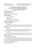
1.2.7 Position/Torque
Position/Torque Operation Mode
Regenerative resistance
MC1
MCCB1
Power supply AC
200-230 [V]
50/60 [Hz]
B1
NF
(Note1)
B2
CN2
L1
L2
L3
L1C
L2C
Servo drive
U
V
W
Output
CN3
Input
DC24V
+24V
CN1
IN
PCON
13
GAIN2
14
PCLEAR
15
TLIMIT
16
ALMRST
17
EMG
18
CWLIM
19
CCWLIM
MODE
20
21
EGR2/SPD2
22
EGR1/SPD1
23
SVON
47
STOP
48
PULCOM
49
38
ALARM+
39
ALARM-
40
RDY+
41
RDY-
42
TLOUT
43
ZSPD
44
BRAKE
45
INPOS
24
GND24
25
GND24
MONITOR Output
(Note2)
-5V ~+5V
28 MONIT1
29 MONIT2
controller
ENCODER Output
PF+
9
32
AO
PF-
10
33
/AO
PR+
11
PR-
12
30
BO
Upper
31
/BO
controller
4
ZO
5
/ZO
Open
collector
Speed
limit
1-16
-5V ~+5V
37 GND
Line driver
driver
Upper
U
V
W
E
0V ~+10V
SPDLIM
27
3
OPCZO
GND
8
36
GND
Connect to Case of connector