Máy đào HuynDai R170W-9 (Phần 6) - P2.1
Bạn đang xem bản rút gọn của tài liệu. Xem và tải ngay bản đầy đủ của tài liệu tại đây (2.83 MB, 20 trang )
SECTION 2 STRUCTURE AND FUNCTIONSECTION 2 STRUCTURE AND FUNCTION
Group 1 Pump Device
------------------------------------------------------------------------------------------------------
2-1
Group 2 Main Control Valve
---------------------------------------------------------------------------------------------
2-20
Group 3 Swing Device
------------------------------------------------------------------------------------------------------
2-47
Group 4 Travel Motor
--------------------------------------------------------------------------------------------------------
2-58
Group 5 RCV Lever
----------------------------------------------------------------------------------------------------------
2-65
Group 6 Accelerator Pedal
-----------------------------------------------------------------------------------------------
2-72
Group 7 Brake Pedal
--------------------------------------------------------------------------------------------------------
2-73
Group 8 Transmission
-------------------------------------------------------------------------------------------------------
2-75
Group 9 Travel Control Valve
--------------------------------------------------------------------------------------------
2-82
Group 10 Steering Valve
----------------------------------------------------------------------------------------------------
2-84
2-1
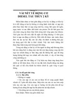
1. STRUCTURE1. STRUCTURE
The pump device consists of main pump, regulator and gear pump.
SECTION 2 STRUCTURE AND FUNCTIONSECTION 2 STRUCTURE AND FUNCTION
GROUP 1 PUMP DEVICEGROUP 1 PUMP DEVICE
Pi1
a4
Dr3
B3
A3
A1 A2
Pi1
Pi2
B1
Qmax adjusting screw
EPPR valve
Front regulator
Rear regulator
Front pump Valve block
Rear pump
Gear pump
Qmin adjusting screw
Qmin adjusting screw
P1
Dr2
a3
Pi2
Hydraulic circuit
Dr1
A
VIEW A
A2
A1
a1
a2
B1
a1
a2
A1
A2
Pi2
Pi1
B3
a3
A3
P1
FRONT REAR
Dr2
B1
Dr1
a4
Dr3
Dr2
KR38-9N37
KR38-9N35
17W92MP01
Port Port name Port size
A1,2 Delivery port SAE6000psi 3/4"
B1 Suction port SAE2500psi 2 1/2"
Dr1 Drain port PF 3/4 - 20
Dr2 Drain port PF 1/2 - 19
Dr3 Drain port PF 3/8 - 15
Pi1, i2 Pilot port PF 1/4 - 15
P1 EPPR valve primary port PF 1/4 - 15
a1,2,3 Gauge port PF 1/4 - 15
a4 Gauge port PF 1/4 - 14
A3 Gear pump delivery port PF 1/2 - 19
B3 Gear pump suction port PF 3/4 - 20.5
2-2
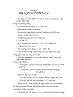
MAIN PUMP (1/2)
The main pump consists of two piston pumps(front & rear) and valve block.
1)1)
111 Drive shaft (F)
113 Drive shaft (R)
116 Gear
123 Roller bearing
124 Needle bearing
127 Bearing spacer
141 Cylinder block
151 Piston
152 Shoe
153 Push-plate
156 Bushing
157 Cylinder spring
211 Shoe plate
212 Swash plate
214 Bushing
251 Support
261 Seal cover (F)
262 Seal cover (R)
271 Pump casing
312 Valve block
313 Valve plate (R)
314 Valve plate (L)
401 Hexagon socket bolt
406 Hexagon socket bolt
466 VP Plug
467 VP Plug
468 VP Plug
490 Plug
531 Tilting pin
532 Servo piston
534 Stopper (L)
535 Stopper (S)
548 Pin
702 O-ring
710 O-ring
711 O-ring
717 O-ring
719 O-ring
724 O-ring
725 O-ring
727 O-ring
728 O-ring
732 O-ring
774 Oil seal
789 Back up ring
792 Back up ring
808 Hexagon head nut
824 Snap ring
885 Pin
886 Spring pin
901 Eye bolt
953 Set screw
954 Set screw
981 Plate
983 Pin
710
406113152151124719312711901
954
724
534
792702214
548
531
532732789535
808
953
886
717
406
774
111
261
127
123
710
824
251
490
212 211 153 156 157 467
728
468
727
466
725
313 116 885 314 141 981
983
271 401
406
262
808
14W72SF02
2-3
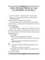
MAIN PUMP (2/2)MAIN PUMP (2/2)
04 Gear pump
115 Shaft
117 Gear No. 2
118 Gear No. 3
125 Ball bearing
126 Roller bearing
128 Bearing spacer
262 Cover
284 Plate
326 Gear case
414 Screw
435 Hexagon socket bolt
468 Plug
710 O-ring
711 O-ring
728 O-ring
825 Retainer ring
826 Retainer ring
885 Spring pin
886 Pin
04
826
115
128
262
885
126
326
414
125
711
284 710 825
435
468 728
118
117
FRONT SIDE REAR SIDE
886
14W92MP03
2-4
REGULATOR (1/2)REGULATOR (1/2)
2)2)
412
876
874
A
B
755
858
614
615
613
611
A
B
VIEW C (FRONT)
897
612
641
730
643
708
644
645
646
SECTION B-B
728
924
801
438
P2
KR38-9N37 (FRONT)
KR38-9N35 (REAR)
A
B
413
438
496
724
725
436
D
D
VIEW C (REAR)
413
438
656
438
722
496
724
725
436
079
735
722
466
755496753
SECTION D-D(REAR)
P1
a
875
P1
a
405
699
Pi
735
Pi
Pi
C
753
Pi
14W92MP04
Port Port name Port size
A Delivery port 3/4"
B Suction port 2 1/2"
Pi Pilot port PF 1/4-15
P1
EPPR valve primary port
PF 1/4-15
P2 Companion delivery port Internal
a
Gauge port
PF 1/4-15
2-5
REGULATOR (2/2)REGULATOR (2/2)
079 EPPR valve assembly
405 Hexagon socket screw
412 Hexagon socket screw
413 Hexagon socket screw
436 Hexagon socket screw
438 Hexagon socket screw
466 Plug
496 Plug
601 Casing
611 Feed back lever
612 Lever (1)
613 Lever (2)
614 Fulcrum plug
615 Adjust plug
621 Compensator piston
622 Piston case
623 Compensator rod
624 Spring seat (C)
625 Outer spring
626 Inner spring
627 Adjust stem (C)
628 Adjust screw (C)
629 Cover (C)
630 Lock nut
631 Sleeve, Pf
641 Pilot cover
643 Pilot piston
644 Spring seat (Q)
645 Adjust stem (Q)
646 Pilot spring
651 Sleeve
652 Spool
653 Spring seat
654 Return spring
655 Set spring
656 Block cover
699 Valve casing
708 O-ring
722 O-ring
724 O-ring
725 O-ring
728 O-ring
730 O-ring
732 O-ring
733 O-ring
734 O-ring
735 O-ring
753 O-ring
754 O-ring
755 O-ring
756 O-ring
763 O-ring
801 Nut
802 Nut
814 Snap ring
836 Snap ring
858 Snap ring
874 Pin
875 Pin
876 Pin
887 Pin
897 Pin
898 Pin
924 Set screw
734
653
654
836
651
652
601
624
629
630
655
641
814
898
631
732
628
756
763
887
626
625
733
622
621
623
754
802
627
SECTION A-A
14W92MP05
2-6
GEAR PUMPGEAR PUMP
3)3)
307 Poppet
308 Seat
309 Spring seat
310 Spring
311 Screw
312 Nut
351 Gear case
353 Drive gear
354 Driven gear
355 Filter
361 Front case
433 Flange socket
434 Flange socket
435 Flange socket
466 Plug
700 Ring
709 O-ring
725 O-ring
732 O-ring
850 Snap ring
887 Pin
434 466,725
435
700 353 351
354
709 361
433
434
311
312
732
310
307 309308
355
850
Dr3 Dr3
a3
B3
887
A3
14W7A2MP06
2-7
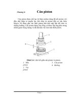
Rotary groupRotary group
The rotary group consists of drive shaft
(F) (111), cylinder block (141), piston
shoes (151,152), set plate (153),
spherical bushing (156) and cylinder
spring (157).
The drive shaft is supported by bearing
(123,124) at its both ends.
The shoe is caulked to the piston to from
a spherical coupling. It has a pocket to
relieve thrust force generated by loading
pressure and the take hydraulic balance
so that it slides lightly over the shoe plate
(211). The sub group composed by a
piston and a shoe is pressed against the
shoe plate by the action of the cylinder
spring via a retainer and a spherical
bush.
Similarly, the cylinder block is pressed
against valve plate (313) by the action of
the cylinder spring.
Swash plate groupSwash plate group
The swash plate group consists of swash
plate (212), shoe plate (211), swash plate
support (251), tilting bushing (214), tilting
pin (531) and servo piston (532).
The swash plate is a cylindrical part
formed on the opposite side of the sliding
surface of the shoe and is supported by
the swash support.
If the servo piston moves to the right or
left as hydraulic force controlled by the
regulator is admitted to hydraulic
chamber located on both sides of the
servo piston, the swash plate slides over
the swash plate support via the spherical
part of the tilting pin to change the tilting
angle (α)
2. FUNCTION2. FUNCTION
MAIN PUMPMAIN PUMP
The pumps may classified roughly into the rotary group performing a rotary motion and working as
the major part of the whole pump function: the swash plate group that varies the delivery rates: and
the valve cover group that changes over oil suction and discharge.
1)1)
(1) (1)
(2)(2)
151
152
157
111
123
153
156
141
313
124
211
531
211
548
214
212
532
251
α
α
21092MP06
2507A2MP14