iS5 Catalog
Bạn đang xem bản rút gọn của tài liệu. Xem và tải ngay bản đầy đủ của tài liệu tại đây (545.59 KB, 24 trang )
Drive Solution
0.75 -55kW(1-75HP) 3 phase 200 -230Volts
0.75 -75kW(1-100HP) 3 phase 380 -460Volts
Variable Frequency Drive / Inverter
Starvert iS5
Starvert iS5
Overview
Features & Selection Guide
Specifications & Wiring
Terminal Configuration, Keypad & Parameter Navigation
Program Parameter Descriptions
Dimension
Options, DB Resistor & Peripheral Devices
RFI Filters
02
04
06
08
10
18
20
22
Contents
Overview
02
Sensorless, sensored vector controlled iS5,
keeps your application in more stable,
durable and precise condition.
Options
■Communications Board:
•RS-485
•DeviceNet
•F-Net
•ModBus-RTU
•ProfiBus DP
•Extended I/O Module
-Sub-A Board:
3 Multi-Function Input
3 Multi-Function Output
-Sub-B Board :
Encoder Plus Input
Encoder Plus Output
-Sub-C Board :
3 Multi-Function Input
3 Multi-Function Output
Aux. Analog Reference Frequency (Isolated)
■Cable for Remote Keypad Operations
■Dynamic Braking Units for 11~75kW Inverters
■Dynamic Braking Resistors
Application
■Traverse
■Draw
■MMC (Mult Motor Control)
■Converting
■Material Handling
■Web Processing
■Fan/Pump Controls
■Conveyors
■Industrial Washing machine, etc.
Conformity to global standards
■UL and cUL listed for North America
■CE marked for Europe
■Quality process controlled by ISO9001, ISO14000
Standard features
■kW / Voltage Ratings:
•0.75~55kW, 200-230VAC, 3 phase
•0.75~75kW, 380-480VAC, 3 phase
■Enclosure: IP00 ~ IP20
■Inverter Type: PWM with IGBT
■Control Method: Sensorless/Sensored Vector
■1~15kHz Carrier Frequency (1~8kHz. over 30kW)
■0~400Hz Output Frequency
■Removable Keypad (Able to read & write parameters)
■Intelligent Accel/Decel for Trip-Free Operation
■Auto Tuning
■8 Multi-Function Inputs
■1 Multi-Function Outputs
■Failure Relay
■Built-in PID Control
■Pre-Set Speeds
■Wire Operation
■Multi-step Programmable Run Patterns
■Auto Torque Boost
■DC Injection Braking
■Stall Prevention
■Built-In Braking Circuit for 0.75 ~ 7.5kW units
Starvert iS5
03
Extended I/O boards
The iS5 has several additional I/O boards that can be easily mounted into the connection terminal on control
board. Each I/O board is standardized for a specific I/O requirement.
The three main I/O boards are "Sub-board A", "Sub-board B" and "Sub-board C".
This helps system engineer to design most adequate and cost effective system
using the exactly necessary number of I/Os and functions.
It is extendable and changeable in case of system upgrade or change.
The control parameters and detailed functions for these boards
are not shown until any of them is inserted.
Diversity of communication interfaces
The iS5 provides most popular communication interfaces such as Device Net, Profibus DP, Modbus-RTU,
RS485 and F-Net (LS proprietary protocol for LS PLC communication).
The "Driveview
TM
" software offers Window
®
based computer monitoring tool through RS-485 interface with
graphic capture, keypad emulator, parameter edit, and text monitor. It is applicable for all LS inverters.
Built-in PID control
It is valuable in process control. The built-in PID algorithm controls flow, temperature, pressure, etc. through the
proportional, integral and differential calculus between the feedback value and reference value in closed loop.
The high speed CPU makes the calculation easy and fast.
Sensorless vector control
The iS5 adopts sensorless vector control algorithm, and it improves not only the torque control characteristics, but the speed
controlability in an uncertain condition caused by the load variation as well.
The iS5 especially generates strong torque at a low speed range as shown below.
04
SV008iS5-4
SV015iS5-4
SV022iS5-4
SV037iS5-4
SV055iS5-4
SV110iS5-4
SV150iS5-4
SV185iS5-4
SV220iS5-4
SV300iS5-4
SV370iS5-4
SV450iS5-4
SV550iS5-4
SV750iS5-4
SV008iS5-2
SV015iS5-2
SV022iS5-2
SV037iS5-2
SV055iS5-2
SV110iS5-2
SV150iS5-2
SV185iS5-2
SV220iS5-2
SV300iS5-2
SV370iS5-2
SV450iS5-2
SV550iS5-2
0.75 1
1.5 2
2.2 3
3.7 5
5.5 7.5
7.5 10
11 15
15 20
18.5 25
22 30
30 40
37 50
45 60
55 75
75 100
Features & Selection Guide
Auto tuning
The auto tuning algorithm in iS5 sets the motor factors automatically. It brings the traditional commissioning difficulties mainly in
low speed by the load variation and the low torque generation to a settlement.
Optimum acceleration and deceleration
To make a maximum torque during the acceleration and deceleration, so called "trip free" function is acting during acceleration
and deceleration. Both of Acceleration and deceleration may cause a trip in case that it is manually programmed. The 32-bit
DSP CPU monitors the current transition during the acceleration and deceleration to program an optimum curve that is under
the triptrigering level automatically.
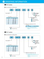
Inverter rating selection guide
Inverter type nomenclature
Application motor
KW HP
200~230V 380~460V
SV 008 iS5 -4 #
LS Starvert inverter
008
015
.
220
0.75kW
1.5kW
.
22kW
iG5
iS5
iH
iV5
iG5 series
iS5 series
iH series*
iV5 series
-2
-4
3 phase 200~230V
3 phase 380~480V
* iH inverter has a different designation in kW.
Stopped
CH1=2V
DC 10:1
CH3=5V
DC 10:1
CH4=2V
DC 10:1
1s/div
[1s/div]
NORM:1kS/s
=Trigger=
Mode : AUTO
Type : EDGE CH1
Delay : 0.0ns
Hold Off : MINIMUM
=Record Length=
Main : 10k
Zoom : 500
=Filter=
Smoothing : OFF
BW : FULL
=Offset=
Ch1 : 0.00V
Ch2 : 0.00V
CH3 : 0.00V
CH4 : 0.00V
3
Stopped
CH1=2V
DC 10:1
CH3=5V
DC 10:1
CH4=2V
DC 10:1
1s/div
[1s/div]
NORM:1kS/s
=Trigger=
Mode : AUTO
Type : EDGE CH1
Delay : 0.0ns
Hold Off : MINIMUM
=Record Length==Filter=
Smoothing : OFF
BW : FULL
=Offset=
3
Traditional curve Optimum curve
Trip
Main : 10k
Zoom : 500
Ch1 : 0.00V
Ch2 : 0.00V
CH3 : 0.00V
CH4 : 0.00V
# option built-in
Starvert iS5
05
Specifications 200~230V Class (0.75~55kW)
Inverter Type (SV_ _ _iS5-_)
Motor Rating*
1)
Output ratings
Input ratings
Weight[kg]
[HP]
[kW]
Capacity[kVA]
*2)
FLA[A]
Frequency
Voltage
Voltage
Frequency
1
0.75
1.9
5
4.6
008-2 015-2 022-2 037-2 055-2 075-2 110-2 150-2 185-2 220-2 300-2 370-2 450-2 550-2
2
1.5
3
8
4.6
3
2.2
4.5
12
4.8
5
3.7
6.1
16
4.9
7.5
5.5
9.1
24
7.5
10
7.5
12.2
32
7.7
15
11
17.5
46
13.8
20
15
22.9
60
14.3
25
18.5
28.2
74
19.4
30
22
33.5
88
20
40
30
46
122
50
37
55
146
60
45
68
180
75
55
84
220
0 ~ 400 Hz
200 ~ 230V*
3)
3 phase 200 ~ 230 V (±10%)
50 ~ 60 Hz (±5%)
Specifications 380~480V Class (0.75~75kW)
Inverter Type (SV_ _ _iS5-_)
Motor Rating*
1)
Output ratings
Input ratings
Weight[kg]
Braking Torque
Cooling method
Enclosure
Braking circuit
Average braking torque
Max.continuous
braking
Max. duty
100%
5seconds
30 (3)%ED
100%
5seconds
30 (2)%ED
100%
5seconds
30 %ED
Forced air cooling
IP00
150%
Controlled by braking unit*
4)
10 %ED
On board
Control
Operation
Control method
Frequency setting resolution
Frequency accuracy
V/F ratio
Overload capacity
Torque boost
Operation method
Frequency setting
Start signal
Multi-step
Multi-step accel/decel time
Emergency stop
Jog
Auto operation
Fault reset
Operation status
Fault output
Indicator
Operation function
Inverter trip
Inverter alarm
Momentary power loss
Operation information
Trip information
Ambient temperature
Storage temperature
Ambient humidity
Altitude . Vibration
Application side
Key / terminal / communication operation
Analog : 0 ~ 10V / 4 ~ 20 mA / Additional port for Sub-board (0 ~10V)
forward, reverse
Up to 8 speeds can be set (use multi-function terminal)
0 ~ 6,000 sec, up to 8 types can be set and selected for each setting (use the multi- function terminal),
Accel/Decel pattern : linear pattern, U pattern, S pattern
Interrupts the output of the inverter
Jog operation
Operates from internal sequence by setting the multi-function terminal (5way x 8step)Trip status is removed when protective function is
active
Frequency level detection, Overload alarm, stalling, overvoltage, undervoltage, inverter overheating, running, stop,
constant speed, exchange inverter to commercial line, speed searching, auto operation step, auto operation sequence
Contact output (30A,30C,30B) - AC250V 1A, DC30V 1A
Choose 1 from Output frequency, output current, output voltage, DC voltage (Output voltage: 0 ~ 10V)
DC braking, frequency limit, frequency jump, second function, slip compensation, reverse rotation prevention, auto restart,
exchange inverter to commercial line, auto-tuning, PID control
Overvoltage, undervoltage, overcurrent, fuse open, ground fault, inverter overheating, motor overheating, output phase loss,
MC fail (over 30kW only), overload protection, external fault 1,2, communication error, loss of speed command, hardware fault, option fault
etc.
Stall prevention, overload alarm
Less than 15 msec : continuous operation (over 30kW drives excluded), more than 15 msec : auto restart possible
Output frequency, output current, output voltage, frequency value setting, operating speed, DC voltage
Indicates the fault when the protection function activates, memorizes up to 5 faults
-10 °C ~ 40 °C
-20 °C ~ 65 °C
90 % RH max.(Non condensing)
Below 1,000 m˙below 5.9m/sec
2
(=0.6g)
No corrosive gas, combustible gas, oil mist, or dust
V/F control, sensorless vector control(selectable), sensored vector control
Digital reference : 0.01 Hz (below 100 Hz), 0.1 Hz (over 100 Hz) Analog reference : 0.03 Hz / 50 Hz
Digital : 0.01% of max. output frequency Analog : 0.1% of max. output frequency
Linear, Square pattern, User V/F
150 % of rated current for 1 min., 200% of rated current for 0.5 sec. (characteristic is inversely proportional to time)
Manual torque boost (0 ~ 15 %), Auto torque boost
Optional (Braking unit, resistor)
[HP]
[kW]
Capacity[kVA]
*2)
FLA[A]
Frequency
Voltage
Voltage
Frequency
1
0.75
1.9
2.5
4.6
008-4 015-4 022-4 037-4 055-4 075-4 110-4 150-4 185-4 220-4 300-4 370-4 450-4 550-4 750-4
2
1.5
3
4
4.6
3
2.2
4.5
6
4.8
5
3.7
6.1
8
4.9
7.5
5.5
9.1
12
7.5
10
7.5
12.2
16
7.7
15
11
18.3
24
13.8
20
15
22.9
30
14.3
25
18.5
29.7
39
19.4
30
22
34.3
45
20
40
30
45
61
50
37
56
75
60
45
68
91
75
55
82
110
100
75
100
152
0 ~ 400 Hz
380 ~ 480V*
3)
3 phase 380 ~ 480V (±10%)
50 ~ 60 Hz (±5%)
*1) Indicates the maximum applicable capacity when using 4 pole LS standard motor.
*2) Rated capacity ( 3*V*I) is based on 220V for 200V class and 440V for 400V class.
*3) Maximum output voltage will not be greater than the input voltage. Output voltage less than the input voltage can be set.
*4) 0.75 ~ 3.7kW inverter have internal braking resistor inside. 5.5 ~ 75kW inverters need optional braking resistor.
Input signal
Output signal
Protective
function
Display
Keypad
Environment
√
Specifications & Wiring
06
Wiring
DB ResistorDC Bus Choke
Dynamic
Braking Unit
DB UNIT(OPTION)
*4
DB Resistor
MOTOR
U
P1
*1
P2
*1
N
*1
V
W
R
MCCB(OPTION)
*4
DC BUS CHOKE
(OPTION)
*3
3ф
230/460V
50/60Hz
S
T
G
FX
RX
BX
RST
JOG
P1
P2
P3
CM
VR
30A
30C
30B
AXA
AXC
FM
5G
V1
I
5G
Forward Run/Stop
Reverse Run/Stop
Invert Disable
Fault Reset
Jog
Multi-function Input 1
Multi-function Input 2
Multi-function Input 3
Common Terminal
Potentiometer
(1kohm, 1/2W)
Shield
Factory Setting
‘Speed-L‘
‘Speed-M‘
‘Speed-H‘
Power supply for
speed signal:
+11V, 10mA
Output Frequency Meter
(0 - 10V : pulse output)
Fault output relay
Iess than AC250V, 1A
Iess than DC30V, 1A
Mult-function output relay1
Iess than AC250V, 1A
Iess than DC30V, 1A
Factory setting:‘RUN‘
Speed signal input:
0 ~10V
Speed signal input:
4 ~ 20mA(250ohm)
Common for
VR, V1, I
Speed signal Input
*2
+
P N B1 B2
FM
Note) "●" display main circuit terminals, "○" display control circuit terminals.
1. The terminal configuration varies depend on the model name.
`P`terminal is available in 5.5 to 7.5kW inverters. `P1` and `P2` are available in 11 to 75kW inverters.
`B1` and `B2` terminals are for braking resister or connection. `P1` and `P2` are for braking unit.
2. Analog speed command can be set by voltage, current and both of them.
3. When installing the DC Reactor, the common busbar between P1 and P2 must be removed.
4. 0.75 ~ 7.5kW inverters have on-board braking circuit. Braking resistor is only included for 0.75 ~ 3.7kW inverters.
11 ~ 75kW inverters need optional braking unit and resister for dynamic braking.
5. Marked as “CM” for over 30kW drives.
Starvert iS5
07
Power terminal configuration
Keypad
1. LCD Keypad
Symbol Function
R
S
T
U
V
W
P
P1
P2
B1
B2
N
G
AC Line input (3 phase, 200~230 Vac for "-2" units and 380~480 Vac for "-4" units)
3 phase output terminals to motor
Positive DC Bus Terminals, DC Bus Choke (reactor)connection terminals. These terminals are available for 5.5 to 7.5kW inverter with optional DB unit
when an application need braking torque over 30% ED
Positive DC Bus Terminals, DC Bus Choke (reactor)connection terminals. These terminals are available for 11 to 22kW inverter with optional DB unit.
These terminal are shorted when DB unit is not applied.
Dynamic braking resistor connection terminals. These terminals are available for 0.75 to 3.7kW inverters in order to connect an external braking resistor.
Negative DC Bus terminal
Chassis ground (The ground terminal ("G") may be located on heat sink instead of terminal strip depend on the model type)
Control terminal configuration
TypeTypeTypeTypeTypeTypeTypeTypeTypeTypeTypeTypeTypeTypeTypeTypeTypeTypeTypeTypeTypeTypeTypeTypeTypeTypeTypeTypeTypeTypeTypeTypeTypeTypeTypeTypeTypeTypeTypeTypeTypeTypeTypeTypeTypeTypeTypeTypeType
Starting Contact
Function
Selection
Analog/Digital
Pulse
Contact
RS232
Type Symbol
P1, P2, P3
FX
RX
JOG
BX
RST
CM
NC
VR
V1
I
5G
FM
30A,30C,30B
AXA,AXC
CN3
Name
Multi function input 1,2,3
Forward run command
Reverse run command
Jog frequency reference
Emergency stop
Fault reset
Sequence common
-
Frequency setting power (+12V)
Frequency reference (Voltage)
Frequency reference (Current)
Frequency setting common terminal
Analog/digital output
(For external monitoring)
Fault contact output
Multi-function output
Communication port
Description
Used for multi function input. Factory default is set to step frequency 1, 2, 3.
Forward run when closed and stop when open.
Reverse run when closed and stop when open.
Runs at jog frequency when the jog signal is ON. The direction is set by the FX (or BX) signal.
When the BX signal is ON, the output of the inverter is cut off. When the motor uses an electrical brake to stop,
BX is used to cut off the output signal. When the BX signal, which does not cut off by latching, is OFF and the
FX signal (or the RX signal) is ON, the motor keeps running, so be cautious.
Used to release the protective status when the protective circuit is active.
Used for the common terminal for contact input terminals.
Not used.
Used as power for the analog frequency setting. Maximum output is +12V, 100mA.
Used for frequency reference and uses 0-10V for input. Input resistance is 20 kΩ
Used for frequency reference and uses DC 4-20mA for input. Input resistance is 250Ω
Common terminal for the analog frequency reference signal and the FM (for monitoring).
Outputs one of the followings: output frequency, output current, output voltage, DC link voltage.
Factory default is set to output frequency. Maximum output voltage and output current is 0-12V, 1mA.
Output frequency is set to 500Hz.
Activates when the protective function is operating. AC250V 1A or less, DC30V 1A or less
Fault : 30A-30C short (30B-30C open)
Normal : 30B-30C short (30A-30C open)
Use after defining the multi-function output terminal. AC250V 1A or less, DC30V 1A or less.
Use the keypad connector. Use the keypad connector for RS232 communication. Disconnect the keypad
and connect the RS232-RS485 converter for RS485 communication.
Input signal
Output signal
Comm.
Key/LED Description
MODE
PROG
ENT
UP
DOWN
SHIFT/ESC
REW
STOP/RESET
FWD
REV
STOP/RESET
FWD
Name
Mode key
Program key
Enter key
Up key
Down key
Shift key
Escape key
Reverse key
Stop key
Reset key
Forward key
Reverse run
Stop/reset
Forward run
The mode button moves you through the seven program groups : DRV, FUN1, FUN2, I/O, (EXT), (COM) and APP.
The program button is used to go into programming mode to change data.
The enter button is used to enter changed parameters.
The up and down arrows are used to move through and change data.
The button is used to move cursor across the display in a programming mode.
This button is used to move the program code to DRV00 from any program code.
The reverse run button is used to run the motor in reverse direction.
The stop button is used to the drive from running.
The reset button is used to reset faults.
The forward run button is used to run the motor in forward direction.
The LED blinks when th inverter accels or decels.
The LED blinks when there is a fault.
The LED blinks when the inverter accels or decels.
▲
▼
2. LED Keypad (7-segment)
Encoder knob
SET
SHIFT/ESC
STOP/RESET
RUN
SET
STOP/RESET
RUN
DRV
FU1
FU2
I/O
EXT
I/O+EXT
I/O+EXT+FU2
Encoder Knob
Set key
Shift key
Escape key
Stop key
Reset key
Run key
Setting status
Stop/Fault status
Run status
Drive group
Function1 group
Function2 group
I/O group
Sub-board group
Option-board group
Application group
This is used to move you through seven parameter groups and parameter codes. Also,
used to change data by rotating knob.
This is used to go into program mode to change data and to enter the changed data.
This is used to go into program mode to change data and to enter the changed data.
This button is used to move cursor across the display in a programming mode.
This is used to stop the inverter from running.The reset button is used to reset faults.
This is used to run the inverter.
The motor direction is set in DRV13.
It blinks in setting mode.
The LED is lit in Stop status and blinks in fault status.
The LED is lit in Run status and blinks in fault status.
It blinks in drive group.
It blinks in Function1 group.
It blinks in Function2 group.
It blinks in I/O group.
It blinks in Sub-board group.
It blinks in Option board group.
It blinks in Application group.
MODE PROG
LC-200
ENT
FWDREV
SHIFT
ESC
STOP
RESET
PROG
ENT
LC-200
RUN
SHIFT
ESC
STOP
RESET
DRV FU1 FU2 I / O EXT
Terminal Configuration, Keypad & Parameter Navigation
08
Parameter group
Parameter navigation
Drive
Function 1
Function 2
Input / Output
External board
Communication
Application
Parameter group
LCD keypad
DRV
FU1
FUN2
I/O
EXT
COM
APP
7-segment keypad
DRV LED is lit
FU1 is lit
FU2 is lit
I/O is lit
EXT is lit
I/O + EXT are lit
I/O + EXT + FU2 are lit
Description
Command frequency, accel/decel time, etc. Basic parameters.
Max. frequency, amount of torque boost, etc. Basic function related parameters.
Frequency jumps, max./min. limit of frequency etc. Application function related parameters.
Multi function terminal setting, auto operation etc. Parameter needed for sequence operation.
Displayed when sub-board is installed.
Displayed when option board is installed.
Specific application related parameters.
1. LCD Keypad
MODE
MODE
MODE
MODE
MODE
MODE
MODE
DRV T/K 0.0A
00 STP 60.00Hz
FU1 Jump coad
00 1
FU2 Jump coad
00 30
I/O Jump coad
00 1
DRV Acc. time
01 10.0sec
FU1
Run prohibit
03 None
FU2 last trip-1
01
______
I/O V1 filter
01 10ms
MODE MODE MODE MODE
DRV Dc. time
02 20.0sec
FU1
Acc.Pattern
05 Linear
FU2 last trip-2
02
______
I/O V1voltx1
02 0.00V
MODE MODE MODE MODE
DRV Drive mode
03 Fx/Rx-1
FU1
Dec.Pattern
06 Linear
FU2 last trip-3
03
______
I/O V1 freqy1
03 0.00Hz
MODE MODE MODE MODE
DRV Freq mode
04 Keypad-1
FU1 Stop mode
07 Decel
FU2 last trip-4
04
______
I/O V1 voltx2
04 10.00V
MODE MODE MODE MODE
DRV Step freq-1
05 10.00Hz
FU1 DcStvalue
08 50%
FU2 last trip-5
05
______
I/O V1 freq y2
03 60.00Hz
MODE
DRV Fault
12
- - - - - - - - - - -
MODE
FU1
Stall Level
60 150%
MODE
FU2 Para.lock
94 0
MODE
I/O Way1/2D
60 Forward
MODE
Drive group Function1 group Function2 group I / O group