KRONE - Guide Book - KRONE Instalation pratices
Bạn đang xem bản rút gọn của tài liệu. Xem và tải ngay bản đầy đủ của tài liệu tại đây (2 MB, 71 trang )
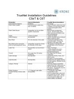
Cable Installation Guide
KRONE is obliged by European Law to make course
attendees aware of Health and Safety rules and correct
working practices.
General Safety Rules
When working in an office, mark off areas where cables
could be a potential hazard
Remove all customer’s items that could be damaged
during the installation.
Remember: A tidy job is a safe job!
Personal Protective Equipment
Hard hats must be worn on all building sites.
Protective shoes must be worn at all times.
Protective gloves should be worn when pulling in cables.
Goggles must be worn when removing ceiling tiles or
when drilling and chopping into walls.
It is advisable to wear protective overalls to stop
loose clothing getting caught.
• Before using ladders and stepladders, make sure the
correct Safety Procedures are followed for:
– Siting
– Right ladder for right job
– Bad weather use
– Slippery surfaces
Ladder Safety
• If you think you may be working in an area
where asbestos or other suspect substances are
present:
– Stop and inform your supervisor.
– Always ask your Supervisor if you have to
work in the proximity of unknown substances.
• Always observe your national Health and Safety
at Work regulations.
Hazardous Materials
• A careful survey of cabling and wiring routes should
always be made to select the best possible routes.
• The time taken completing a site survey of cable
routes will expedite the installation.
• Look for possible routes:
– Suspended floors
– Suspended ceilings
– Building risers
Possible Cable Routes
• Floor access traps should not be left open and
unguarded.
• When working in a floor access use proper
guard rails round tile access.
• As soon as work is completed all covers and
fixing screws should be properly secured.
Precautions for sub-floor & ducting access
Power Separation Distances
Distance A
Type of Installation
Without Divider,
or with Non-
Metallic Divider
Aluminium
Divider
Steel
Divider
Unscreened power cable
and unscreened IT cable
Unscreened power cable
and screened IT cable
2
Screened power cable
and unscreened IT cable
Screened power cable
and screened IT cable
2
200mm
50mm
30mm
0mm
100mm
20mm
10mm
0mm
50mm
5mm
2mm
0mm
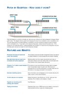
Recommended Pathway Separation Distances
Auxiliary
Circuits
Power
Cabling
IT Cabling
Sensitive
Circuits
Not Recommended
Metallic Cable Trays
Correct Practice
Power
Cabling
Auxiliary
Circuits
IT Cabling
Sensitive
Circuits
Recommended
Recommended Pathway Separation Distances
• BS EN 50174-2 states that:
• Data cables and power cables must not share the
same duct or conduit:
• Use site plans to estimate length of cable needed, remembering
to leave at least:
– 50cm at socket
– 2 meters at frame (for terminating).
• For short runs pace out length.
• For suspended ceilings, remember to include length to ceiling
and drop to floor.
• Do not exceed the cable lengths specified in the Standards.
• Consideration should be given to the use of fire retardant cable
with low smoke emission properties such as LSZHFR. (Low
Smoke Zero Halogen Flame Retardant).
Cable Estimation
• Tray work should be used when available, but must be
segregated from other cables.
• Route round walls or under the floor using trunking, if this is not
possible, use cable tray in the ceiling space.
• On no account should cables be suspended from ceiling
support hangers.
• Where tray work is not available. Fixing to the top ceiling must
be made every 300mm max.
• When cables are concealed, they must be labelled at all points
where they enter and emerge.
• On no account should cables run near fluorescent lights and
inductive circuits.
Cable Routes
Cable Routes: Containment
Cable Tray Sections:
Trays Bends Risers
Cross-Pieces T-pieces
Cable Tray Installation Products:
Stand-off Brackets Cantilever Arms
Trapeze Hangers Overhead Hangers Couplers
Cable Routes: Containment
Position support brackets 150mm
either side of corner sections, bends,
T-pieces or Cross-pieces
150mm
Cable Routes: Containment
When fitting horizontal tray to the floor, use
stand-off brackets to allow access
underneath the tray
When bolting the trays to the support
brackets ensure the bolt head is inside
the tray, to prevent snagging and
cable damage
Cable Routes: Containment
Conduit - Trunking - Cable Tray - Basket Tray
Turning Boxes etc...
All new types of containment must not be
loaded more than 50% of capacity at the
time of new installation.
25% is further available for expansion.
The total fill rate of containment must not
exceed 75%.
Cable Routes: Containment
Conduit Installation
If there are more than 2
bends, a turning box is
required
Cable Routes: Containment
Cantilever Installation
– Dress cables on to cantilever supported trays with the
larger bundles close to the supporting wall. This will
reduce the leverage on the wall fixings.
Cable Routes: Containment
Risers & Vertical Trunking Support
– Vertical trunking must have some means of cable support
– If the trunking product does not provide for cable support drill
holes through the trunking and into the supporting wall. Fit a
product such as tie plugs and use cable ties to support the
cables
Cable Dressing
Do not dress cables against sharp edges i.e. cable tray
angled bends, cut-off cable trays etc.
• Label the ends of cable and the corresponding box. This will
help for identification purposes at the central distribution frame
and socket
Box Labelling
• Don’t cut corners with cable - leave ample slack. A metre or so
of cable costs a lot less than the time it takes to redo a cable run
because of cable lengths being too short or the cable being
stretched.
• When you wire the jacks and patch panel you should have
enough slack to reach the floor and extend another metre at
both ends of the cable.
– In addition, it’s standard practice to leave a service loop (not
a coil) of 2 meters inside the ceiling or other out-of-the-way
place. However, do not exceed the 90m rule.
Spare Cable
Example: Cabinet Layout
Horizontal
Wiring to
Outlets
Active
Components
PABX
Fibre
Notes
• Mains distribution for the rack is located at the back of the
cabinet and is fed from an unswitched fused spur which is in
turn derived from an independent feed on the mains
distribution board within the building
• The mains cables to the communications equipment should
formed into a neat cable loom with fabric hook and loop ties
and kept away from any voice or data cables. The metalwork
of the rack or cabinet should be bonded to earth.
• Cable management for permanent wiring is located at the
back of the cabinet and secured ideally using Velcro ties.
Installation practices
Right and Wrong