Network Virtualization — Path Isolation Design Guide
Bạn đang xem bản rút gọn của tài liệu. Xem và tải ngay bản đầy đủ của tài liệu tại đây (4.4 MB, 160 trang )
Americas Headquarters:
© 2007 Cisco Systems, Inc. All rights reserved.
Cisco Systems, Inc., 170 West Tasman Drive, San Jose, CA 95134-1706 USA
Network Virtualization—Path Isolation Design
Guide
Contents
Introduction
3
Path Isolation Overview
6
Policy-Based Path Isolation
7
Control Plane-Based Path Isolation
8
Network Device Virtualization with VRF
9
Data Path Virtualization—Single- and Multi-Hop Techniques
11
Path Isolation Initial Design Considerations
12
Path Isolation Using Distributed Access Control Lists
14
Connectivity Requirements
15
Configuration Details
15
Path Differentiation
17
High Availability Considerations
19
Challenges and Limitations of Distributed ACLs
19
Path Isolation over the WAN using Distributed ACLs
19
Path Isolation using VRF-Lite and GRE
21
Connectivity Requirements
21
Configuration Details
23
Using Point-to-Point GRE
23
Using mGRE Technology
32
MTU Considerations
37
Loopback IP Address Considerations
39
High Availability Considerations
43
Using VRF-Lite and GRE over the WAN
44
2
Network Virtualization—Path Isolation Design Guide
OL-13638-01
Contents
Configuration Details
49
QoS in Hub-and-Spoke Deployments
51
Wired Clients
52
Wireless Clients
59
Challenges and Limitations Using VRF and GRE
68
Path Isolation Deploying MPLS VPN
69
MPLS VPN Technology Overview
69
MPLS Rehearsal
69
MPLS VPN Rehearsal
72
MPLS VPN in Campus
75
High Level Design Principles
75
Network Topologies
77
Network Device Roles
79
VRF and MPLS on Catalyst 6500 Platforms
80
Virtualizing the Campus Distribution Block
95
Configuring the Core Devices (P Routers)
117
Redundancy and Traffic Load Balancing
118
Dealing with MTU Size Issues
124
Tagging or not-Tagging Global Table Traffic
127
Convergence Analysis for VPN and Global Traffic
130
Summary of Design Recommendations
138
MPLS-Specific Troubleshooting Tools
139
Extending Path Isolation over the WAN
141
Overview
141
Design Options—Three Deployment Models
141
Initial Conditions
142
Enterprise MPLS Terminology
142
Mapping Enterprise VRFs to Service Provider VPN (Profile 1)
143
Connecting the Enterprise to the Service Provider
145
QoS on the WAN Interface
145
Routing within a VRF
147
Scale Considerations
148
Multiple VRFs Over a Single VPN (Profile Two)
148
Isolation versus Privacy
149
MPLS with DMVPN
150
Routing Over VRF-Mapped DVMPN Tunnels
151
Scale Considerations
153
Extending the Enterprise Label Edge to the Branch (Profile 3)
154
Setting up BGP over the WAN
155
Route Reflector Placement
155
3
Network Virtualization—Path Isolation Design Guide
OL-13638-01
Introduction
Integration of Campus and WAN Route Reflectors
155
Label Distribution
155
WAN Convergence
156
MTU Considerations
157
QoS Features
157
Scalability Considerations
158
General Scalability Considerations
158
Multiple Routing Processes
158
Branch Services
159
IOS Firewall Services
159
IOS IPS
159
DHCP Server
159
WAN Path Isolation—Summary
159
Introduction
The term network virtualization refers to the creation of logical isolated network partitions overlaid on
top of a common enterprise physical network infrastructure, as shown in
Figure 1.
Figure 1 Creation of Virtual Networks
Each partition is logically isolated from the others, and must provide the same services that are available
in a traditional dedicated enterprise network. The end user experience should be as if connected to a
dedicated network providing privacy, security, an independent set of policies, service level, and even
routing decisions. At the same time, the network administrator can easily create and modify virtual work
environments for various user groups, and adapt to changing business requirements adequately. The
latter is possible because of the ability to create security zones that are governed by policies enforced
centrally; these policies usually control (or restrict) the communication between separate virtual
221035
Virtual Network
Physical Network Infrastructure
Virtual Network Virtual Network
4
Network Virtualization—Path Isolation Design Guide
OL-13638-01
Introduction
networks or between each logical partition and resources that can be shared across virtual networks.
Because policies are centrally enforced, adding or removing users and services to or from a VPN
requires no policy reconfiguration. Meanwhile, new policies affecting an entire group can be deployed
centrally at the VPN perimeter. Thus, virtualizing the enterprise network infrastructure provides the
benefits of using multiple networks but not the associated costs, because operationally they should
behave like one network (reducing the relative OPEX costs).
Network virtualization provides multiple solutions to business problems and drivers that range from
simple to complex. Simple scenarios include enterprises that want to provide Internet access to visitors
(guest access). The stringent requirement in this case is to allow visitors external Internet access, while
simultaneously preventing any possibility of unauthorized connection to the enterprise internal resources
and services. This can be achieved by dedicating a logical “virtual network” to handle the entire guest
communication path. Internet access can also be combined with connectivity to a subset of the enterprise
internal resources, as is typical in partner access deployments.
Another simple driver for network virtualization is the creation of a logical partition dedicated to the
machines that have been quarantined as a result of a Network Admission Control (NAC) posture
validation. In this case, it is essential to guarantee isolation of these devices in a remediation segment of
the network, where only access to remediation servers is possible until the process of cleaning and
patching the machine is successfully completed.
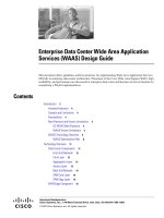
Complex scenarios include enterprise IT departments acting as a service provider, offering access to the
enterprise network to many different “customers” that need logical isolation between them. In the future,
users belonging to the same logical partitions will be able to communicate with each other and to share
dedicated network resources. However, some direct inter-communication between groups may be
prohibited. Typical deployment scenarios in this category include retail stores that provide on-location
network access for kiosks or hotspot providers.
The architecture of an end-to-end network virtualization solution targeted to satisfy the requirements
listed above can be separated in the following three logical functional areas:
•
Access control
•
Path isolation
•
Services edge
Each area performs several functions and must interface with the other functional areas to provide the
end-to-end solution (see
Figure 2).
5
Network Virtualization—Path Isolation Design Guide
OL-13638-01
Introduction
Figure 2 Network Virtualization Framework
The functionalities highlighted in Figure 2 are discussed in great detail in separate design guides, each
one dedicated to a specific functional area.
•
Network Virtualization—Access Control Design Guide (OL-13634-01)—Responsible for
authenticating and authorizing entities connecting at the edge of the network; this allows assigning
them to their specific network “segment”, which usually corresponds to deploying them in a
dedicated VLAN.
•
Network Virtualization—Services Edge Design Guide (OL-13637-01)—Central policy enforcement
point where it is possible to control/restrict communications between separate logical partitions or
access to services that can be dedicated or shared between virtual networks.
The path isolation functional area is the focus of this guide.
This guide mainly discusses two approaches for achieving virtualization of the routed portion of the
network:
•
Policy-based network virtualization—Restricts the forwarding of traffic to specific destinations,
based on a policy, and independently from the information provided by the control plane. A classic
example of this uses ACLs to restrict the valid destination addresses to subnets in the VPN.
•
Control plane-based network virtualization—Restricts the propagation of routing information so
that only subnets that belong to a virtual network (VPN) are included in any VPN-specific routing
tables and updates. This second approach is the main core of this guide, because it allows
overcoming many of the limitations of the policy-based method.
Various path isolation alternatives technologies are discussed in the sections of this guide; for the reader
to make good use of this guide, it is important to underline two important points:
•
This guide discusses the implementation details of each path isolation technology to solve the
business problems previously discussed, but is not intended to provide a complete description of
each technology. Thus, some background reading is needed to acquire complete familiarity with
221036
GRE
VRFs
MPLS
Access Control
Functions
Path Isolation Services Edge
Branch - Campus WAN – MAN - Campus
Authenticate client (user,
device, app) attempting to
gain network access
Authorize client into a
Partition (VLAN, ACL)
Deny access to
unauthorized clients
Maintain traffic partitioned over
Layer 3 infrastructure
Transport traffic over isolated
Layer 3 partitions
Map Layer 3 Isolated Path to VLANs
in Access and Services Edge
Provide access to services:
Shared
Dedicated
Apply policy per partition
Isolated application environments
if necessary
Data Center - Internet Edge -
Campus
IP
LWAPP
6
Network Virtualization—Path Isolation Design Guide
OL-13638-01
Path Isolation Overview
each topic. For example, when discussing MPLS VPN deployments, some background knowledge
of the technology is required, because the focus of the document is discussing the impact of
implementing MPLS VPN in an enterprise environment, and not its basic functionality.
•
Not all the technologies found in this design guide represent the right fit for each business
requirement. For example, the use of distributed access control lists (ACLs) or generic routing
encapsulation (GRE) tunnels may be particularly relevant in guest and partner access scenarios, but
not in deployments aiming to fulfill different business requirements. To properly map the
technologies discussed here with each specific business requirement, see the following
accompanying deployment guides:
–
Network Virtualization—Guest and Partner Access Deployment Guide (OL-13635-01)
–
Network Virtualization—Network Admission Control Deployment Guide (OL-13635-01)
Path Isolation Overview
Path isolation refers to the creation of independent logical traffic paths over a shared physical network
infrastructure. This involves the creation of VPNs with various mechanisms as well as the mapping
between various VPN technologies, Layer 2 segments, and transport circuits to provide end-to-end
isolated connectivity between various groups of users.
The main goal when segmenting the network is to preserve and in many cases improve scalability,
resiliency, and security services available in a non-segmented network. Any technology used to achieve
virtualization must also provide the necessary mechanisms to preserve resiliency and scalability, and to
improve security.
A hierarchical IP network is a combination of Layer 3 (routed) and Layer 2 (switched) domains. Both
types of domains must be virtualized and the virtual domains must be mapped to each other to keep
traffic segmented. This can be achieved when combining the virtualization of the network devices (also
referred to as “device virtualization”) with the virtualization of their interconnections (known as “data
path virtualization”).
In traditional (that is, not virtualized) deployments, high availability and scalability are achieved through
a hierarchical and modular design based on the use of three layers: access, distribution, and core.
Note
For more information on the recommended design choices to achieve high availability and scalability in
campus networks, see the following URL:
/>Much of the hierarchy and modularity discussed in the documents referenced above rely on the use of a
routed core. Nevertheless, some areas of the network continue to benefit from the use of Layer 2
technologies such as VLANs (typically in a campus environment) and ATM or Frame Relay circuits
(over the WAN). Thus, a hierarchical IP network is a combination of Layer 3 (routed) and Layer 2
(switched) domains. Both types of domains must be virtualized and the virtual domains must be mapped
to each other to keep traffic segmented.
Virtualization in the Layer 2 domain is not a new concept: VLANs have been used for years. What is
now required is a mechanism that allows the extension of the logical isolation over the routed portion of
the network. Path isolation is the generic term referring to this logical virtualization of the transport. This
can be achieved in various ways, as is discussed in great detail in the rest of this guide.
Virtualization of the transport must address the virtualization of the network devices as well as their
interconnection. Thus, the virtualization of the transport involves the following two areas of focus:
7
Network Virtualization—Path Isolation Design Guide
OL-13638-01
Path Isolation Overview
•
Device virtualization—The virtualization of the network device; this includes all processes,
databases, tables, and interfaces within the device.
•
Data path virtualization—The virtualization of the interconnection between devices. This can be a
single-hop or multi-hop interconnection. For example, an Ethernet link between two switches
provides a single-hop interconnection that can be virtualized by means of 802.1q VLAN tags;
whereas for Frame Relay or ATM transports, separate virtual circuits can be used to provide data
path virtualization. When an IP cloud is separating two virtualized devices, a multi-hop
interconnection is required to provide end-to-end logical isolation. An example of this is the use of
tunnel technologies (for example, GRE) established between the virtualized devices deployed at the
edge of the network.
In addition, within each networking device there are two planes to virtualize:
•
Control plane—All the protocols, databases, and tables necessary to make forwarding decisions and
maintain a functional network topology free of loops or unintended black holes. This plane can be
said to draw a clear picture of the topology for the network device. A virtualized device must have
a unique picture of each virtual network it handles; thus, there is the requirement to virtualize the
control plane components.
•
Forwarding plane—All the processes and tables used to actually forward traffic. The forwarding
plane builds forwarding tables based on the information provided by the control plane. Similar to
the control plane, each virtual network has a unique forwarding table that needs to be virtualized.
Furthermore, the control and forwarding planes can be virtualized at different levels, which map directly
to different layers of the OSI model. For instance, a device can be VLAN-aware and therefore be
virtualized at Layer 2, yet have a single routing table, which means it is not virtualized at Layer 3. The
various levels of virtualization are useful, depending on the technical requirements of the deployment.
There are cases in which Layer 2 virtualization is enough, such as a wiring closet. In other cases,
virtualization of other layers may be necessary; for example, providing virtual firewall services requires
Layer 2, 3, and 4 virtualization, plus the ability to define independent services on each virtual firewall,
which perhaps is Layer 7 virtualization.
Policy-Based Path Isolation
Policy-based path isolation techniques restrict the forwarding of traffic to specific destinations, based on
a policy and independently of the information provided by the forwarding control plane. A classic
example of this uses an ACL to restrict the valid destination addresses to subnets that are part of the same
VPN.
Policy-based segmentation is limited by two main factors:
•
Policies must be configured pervasively (that is, at every edge device representing the first L3 hop
in the network)
•
Locally significant information (that is, IP address) is used for policy selection
The configuration of distributed policies can be a significant administrative burden, is error prone, and
causes any update in the policy to have widespread impact.
Because of the diverse nature of IP addresses, and because policies must be configured pervasively,
building policies based on IP addresses does not scale very well. Thus, IP-based policy-based
segmentation has limited applicability.
As discussed subsequently in Path Isolation Using Distributed Access Control Lists, page 14, using
policy-based path isolation with the tools available today (ACLs) is still feasible for the creation of
virtual networks with many-to-one connectivity requirements, but it is very difficult to provide
any-to-any connectivity with such technology For example, hub-and-spoke topologies are required to
8
Network Virtualization—Path Isolation Design Guide
OL-13638-01
Path Isolation Overview
provide an answer to the guest access problem, where all the visitors need to have access to a single
resource (the Internet). Using ACLs in this case is still manageable because the policies are identical
everywhere in the network (that is, allow Internet access, deny all internal access). The policies are
usually applied at the edge of the Layer 3 domain.
Figure 3 shows ACL policies applied at the
distribution layer to segment a campus network.
Figure 3 Policy-Based Path Isolation with Distributed ACLs
Control Plane-Based Path Isolation
Control plane-based path isolation techniques restrict the propagation of routing information so that only
subnets that belong to a virtual network (VPN) are included in any VPN-specific routing tables and
updates. To achieve control plane virtualization, a device must have many control/forwarding instances,
one for each VPN. This is possible when using the virtual routing and forwarding (VRF) technology that
allows for the virtualization of the L3 devices.
Internet
221172
ACL ACL ACL ACL
ACL ACLACL ACL
9
Network Virtualization—Path Isolation Design Guide
OL-13638-01
Path Isolation Overview
Network Device Virtualization with VRF
A VRF instance consists of an IP routing table, a derived forwarding table, a set of interfaces that use
the forwarding table, and a set of rules and routing protocols that determine what goes into the
forwarding table. As shown in
Figure 4, the use of VRF technology allows the customer to virtualize a
network device from a Layer 3 standpoint, creating different “virtual routers” in the same physical
device.
Note
A VRF is not strictly a virtual router because it does not have dedicated memory, processing, or I/O
resources, but this analogy is helpful in the context of this guide.
Figure 4 Virtualization of a Layer 3 Network Device
Table 1 provides a listing of the VRF-lite support on the various Cisco Catalyst platforms that are
typically found in an enterprise campus network. As is clarified in following sections, VRF-lite and
MPLS support are different capabilities that can be used to provide separate path isolation mechanisms
(VRF-lite + GRE, MPLS VPN, and so on.)
153703
VRF
VRF
Global
Logical or
Physical Int
(Layer 3)
Logical or
Physical Int
(Layer 3)
Ta b l e 1 VRF-Lite Support on Cisco Catalyst Switches
Platform
Minimum Software
Release
Number of
VRF
VRF Routing
Protection
Support
Full MPLS Support
Catalyst 3550 12.1(11)EA1
(EMI resp. IP Svc.)
7
1
Yes No
Catalyst 3560 12.2(25)SEC
(min. IP Svc.)
26
1
Yes No
Catalyst 3750 12.2(25)SEC
(min. IP Svc.)
26
1
Yes No
Catalyst 3750 Metro 12.1(14)AX
(min. IP Svc.)
26 Yes Yes
(min. Adv. IP Svc.)
10
Network Virtualization—Path Isolation Design Guide
OL-13638-01
Path Isolation Overview
One important thing to consider with regard to the information above is that a Catalyst 6500 equipped
with Supervisor 2 is capable of supporting VRFs only when using optical switching modules (OSMs).
The OSM implementation is considered legacy and more applicable to a WAN environment. As a
consequence, a solution based on VRF should be taken into consideration in a campus environment only
if Catalyst 6500 platforms are equipped with Supervisors 32 or 720 (this is why this option is not
displayed in
Table 1).
The use of Cisco VRF-Lite technology has the following advantages:
•
Allows for true routing and forwarding separation—Dedicated data and control planes are defined
to handle traffic belonging to groups with various requirements or policies. This represents an
additional level of segregation and security, because no communication between devices belonging
to different VRFs is allowed unless explicitly configured.
•
Simplifies the management and troubleshooting of the traffic belonging to the specific VRF, because
separate forwarding tables are used to switch that traffic—These data structures are different from
the one associated to the global routing table. This also guarantees that configuring the overlay
network does not cause issues (such as routing loops) in the global table.
•
Enables the support for alternate default routes—The advantage of using a separate control and data
plane is that it allows for defining a separate default route for each virtual network (VRF). This can
be useful, for example, in providing guest access in a deployment when there is a requirement to use
the default route in the global routing table just to create a black hole for unknown addresses to aid
in detecting certain types of worm and network scanning attacks.
In this example, employee connectivity to the Internet is usually achieved by using a web proxy
device, which can require a specific browser configuration on all the machines attempting to connect
to the Internet or having the need to provide valid credentials. Although support for web proxy
servers on employee desktops is common practice, it is not desirable to have to reconfigure a guest
browser to point to the proxy servers. As a result, the customer can configure a separate forwarding
table for using an alternative default route in the context of a VRF, to be used exclusively for a
specific type of traffic, such as guest traffic. In this case, the default browser configuration can be
used.
Catalyst 4500-SupIII/IV/V/V-10GE
Catalyst 4948/4948-10GE
Catalyst ME-X4924-10GE
12.2(18)EW
2
12.2(20)EWA
2
12.2(31)SGA
64
1
64
1
64
1
Yes
Yes
Yes
No
No
No
Catalyst 6500/7600-Sup720 (PFC3A)
Catalyst 6500/7600-Sup720-3B
Catalyst 6500/7600-Sup720-3BXL
Catalyst 6500/7600-Sup32
Catalyst ME-C6524 (currently DC only)
12.2(17b)SXA
12.2(18)SXD
12.2(17b)SXA
12.2(18)SXF
12.2(18)ZU
1000
1000
1000
1000
1000
Yes
Yes
Yes
Yes
Yes
No!
Yes (min. Adv. IP Svc.)
Yes (min. Adv. IP Svc.)
Yes (min. Adv. IP Svc.)
Yes (min. Adv. IP Svc.)
1. No multicast support within VRFs
2. Starting with 12.2(25)SG, VRF-lite is only supported in Enhanced Service Image -> SupII+ no longer provides VRFs.
Table 1 VRF-Lite Support on Cisco Catalyst Switches (continued)
Platform
Minimum Software
Release
Number of
VRF
VRF Routing
Protection
Support Full MPLS Support
11
Network Virtualization—Path Isolation Design Guide
OL-13638-01
Path Isolation Overview
Data Path Virtualization—Single- and Multi-Hop Techniques
The VRF achieves the virtualization of the networking devices at Layer 3. When the devices are
virtualized, the virtual instances in the various devices must be interconnected to form a VPN. Thus, a
VPN is a group of interconnected VRFs. In theory, this interconnection can be achieved by using
dedicated physical links for each VPN (a group of interconnected VRFs). In practice, this is very
inefficient and costly. Thus, it is necessary to virtualize the data path between the VRFs to provide
logical interconnectivity between the VRFs that participate in a VPN.
The type of data path virtualization varies depending on how far the VRFs are from each other. If the
virtualized devices are directly connected to each other (single hop), link or circuit virtualization is
necessary. If the virtualized devices are connected through multiple hops over an IP network, a tunneling
mechanism is necessary.
Figure 5 illustrates single-hop and multi-hop data path virtualization.
Figure 5 Single- and Multi-Hop Data Path Virtualization
The many technologies that virtualize the data path and interconnect VRFs are discussed in the next
sections. The various technologies have benefits and limitations depending on the type of connectivity
and services required. For instance, some technologies are very good at providing hub-and-spoke
connectivity, while others provide any-to-any connectivity. The support for encryption, multicast, and
other services also determine the choice of technologies to be used for the virtualization of the transport.
The VRFs must also be mapped to the appropriate VLANs at the edge of the network. This mapping
provides continuous virtualization across the Layer 2 and Layer 3 portions of the network. The mapping
of VLANs to VRFs is as simple as placing the corresponding VLAN interface at the distribution switch
into the appropriate VRF. The same type of mapping mechanism applies to Layer 2 virtual circuits
(ATM, Frame Relay) or IP tunnels that are handled by the router as a logical interface. The mapping of
VLAN logical interfaces (Switch Virtual Interface [SVI]) and of sub-interfaces to VRFs is shown in
Figure 6.
221174
802.1q 802.1q
IP
L2 based labeling allows single hop data path virtualization
802.1q
Tunnels allow multi-hop data path virtualization
12
Network Virtualization—Path Isolation Design Guide
OL-13638-01
Path Isolation Initial Design Considerations
Figure 6 VLAN to VRF Mapping
Path Isolation Initial Design Considerations
Before discussing the various path isolation alternatives in more detail, it is important to highlight some
initial considerations that affect the overall design presented in the rest of this guide. These assumptions
are influenced by several factors, including the current status of the technology and the specific business
requirements driving each specific solution. As such, they may change or evolve in the future; this guide
will be accordingly updated to reflect this fact.
•
Use of virtual networks for specific applications
The first basic assumption is that even in a virtualized network environment, the global table is
where most of the enterprise traffic is still handled. This means that logical partitions (virtual
networks) are created to provide response to specific business problems (as, for example, guest
Internet access), and users/entities are removed from the global table and assigned to these partitions
only when meeting specific requirements (as, for example, being a guest and not an internal
enterprise employee). The routing protocol traditionally used to provide connectivity to the various
enterprise entities in global table (IGP) is still used for that purpose. In addition, the global IGP may
also be used to provide the basic IP connectivity allowing for the creation of the logical overlay
partitions; this is, for example, the case when implementing tunneling technologies such as
VRF-Lite and GRE or MPLS VPN. In summary, the idea is to maintain the original global table
design and “pull out” entities from the global table only for satisfying specific requirements (the
business drivers previously discussed). This strategy allows support for gradual evolution to a
virtualized from a non-virtualized network; also, it reduces the risk to existing production
applications.
•
Integration of VoIP technologies in a virtualized network
221175
VRF
VRF
VRF
interface ethernet 2/0.100
ip vrf forwarding green
ip address x.x.x.x
encapsulation dot1q 100
interface ethernet 2/0.100
ip vrf forwarding blue
ip address x.x.x.x
802.1q
13
Network Virtualization—Path Isolation Design Guide
OL-13638-01
Path Isolation Initial Design Considerations
When deploying a VoIP architecture to be integrated in a virtualized network, the current best
practice design recommends to keep the main components of the voice infrastructure (VoIP
handsets, Cisco CallManagers, Cisco Unity Servers, and so on) in the global table, together with all
the users that use voice services (using Cisco Communicator software, VT Advantage, and so on).
Reasons for following this recommendation in this phase of the technology include the following:
–
Current lack of VRF-aware voice services such as Survivable Remote Site Telephony (SRST)
or Resource Reservation Protocol (RSVP) for Call Admission Control (CAC), which would
prevent a successful deployment of VoIP technologies at remote locations (without the burden
of replicating the physical network infrastructure, which is against one of the main drivers for
virtualizing the network). Also, Cisco CallManager does not currently officially support
multi-tenant environments.
- Complex configuration required at the services edge of the network to allow the establishment
of voice flows between entities belonging to separate VPNs. This would also require
“punching” holes in the firewall deployed in this area of the network, increasing the security
concerns of the overall solution.
- VoIP can be secured without requiring the creation of a dedicated logical partition for the voice
infrastructure. There are proven tools and design recommendations that can be used for
hardening the voice systems that are inherent in the system and do not require any form of
network virtualization to be implemented. For more information, see the Voice SRND at the
following URL:
/>anchor10
When the VoIP infrastructure is deployed in the global table, the direct consequence is the
recommendation of keeping all the internal users that make use of VoIP applications (such as Cisco
Communicator clients, for example) in the same domain, to not complicate the design too much
when there is a need to establish voice flows between these users and, for example, the VoIP
handsets. This is inline with the recommendation given in the first bullet point dictating the creation
of virtual networks only for specific purposes.
•
Deployment of network virtualization as an overlay design
Another important initial assumption is that the deployment of a virtualized infrastructure
constitutes an overlay design rather than a “rip-and-replace” approach. This means that the goal is
the deployment of network virtualization without impacting (or just with limited impact to) network
design that customers may already have in place. For example, if routing is already deployed using
a specific IGP, the design should focus on demonstrating how to add services to that specific
environment, rather than suggesting to tear apart the network and put a new network in place. This
guide is focused on networks characterized by a single autonomous system (AS) and a single
IGP-based environment, rather than large backbones with dual-redundant BGP cores.
•
Security and VRF considerations
Consider the following with regard to security and VRF:
–
A VRF-enabled network device is different from a completely virtualized device. The latter is
usually referred to as “logical router”, whereas the first is called “virtual router”. A
VRF-enabled device shares device resources (such as CPU, memory, hardware, and so on)
between the various virtual instances supported. This essentially means that a failure of a
problem with one of these shared elements affects all the virtual routers defined in the box.
–
In terms of isolation versus privacy, configuring separate VRFs allows support for multiple
address spaces and for virtualizing both the control and data planes. However, simply doing this
does not ensure the privacy of the information that is exchanged in the context of each VPN. To
provide this extra layer of security, other technologies (such as IPsec) should be coupled with
the specific path isolation strategy implemented.
14
Network Virtualization—Path Isolation Design Guide
OL-13638-01
Path Isolation Using Distributed Access Control Lists
–
The use of VRF does not eliminate the need for edge security features. As previously discussed,
VRFs are enabled on the first L3 hop device; therefore, many of the security features that are
recommended at the edge of the network (access layer) should still be implemented. This is true
for identity-based techniques, such as 802.1x and MAB, which are discussed in Network
Virtualization—Access Control Design Guide (OL-13634-01).
However, it is important to highlight the requirement for integrating other security components,
such as Catalyst Integrated Security Features (CISF) including DHCP Snooping, IP Source
Guard, Dynamic ARP Inspection, or Port Security. In addition to these, Control Plane Policing
(CPP) also needs to be considered to protect the CPU of the network devices. Another factor is
that, as explained in the previous point above, a problem in a specific VRF may affect the CPU
of the virtualized devices causing outages also in the other VRFs defined in the network device.
•
QoS and network virtualization
QoS and network virtualization are orthogonal problems in this phase of the technology. The main
reason is that the DiffServ architecture has been deployed to be oriented around applications. Traffic
originated by different applications (such as voice and video) is classified and marked at the edge
of the network, and this marking information is used across the network to provide it with an
appropriate level of service.
In this phase of the technology, most enterprise routers and switches lack a virtual QoS mechanism.
This means, for example, that the various input and output queues available on the network devices
are not VRF-aware, which essentially implies that there is no capability to treat differently traffic
originated by the same type of application in two different VPNs. For this reason, when discussing
the deployment of QoS technologies in a virtualized network, there are two main strategies that can
be adopted and that are applied to the various path isolation alternatives discussed in this paper:
–
Conform with the DiffServ standard functionality and keep classifying the traffic at the edge on
an application base. This means that flows originating from the same application in different
VPNs are treated in the same way across the network.
–
Define per-VPN policies. This means that all the traffic originating in a specific VPN is
classified in the same way, independently from the application that originated it. This may find
applicability for example in guest access scenarios, where the recommended strategy is to
classify all the traffic originated from the guest user as best effort when below a predefined
threshold. Traffic exceeding the threshold could for example be classified as scavenger so that
it is the first to be dropped in case of network congestion.
The following sections provide more details on various path isolation techniques. The first is the use of
distributed ACLs that, as previously mentioned, can be considered a policy-based mechanism, and is
here discussed as a “legacy” way of limiting communication between users belonging to different
network partitions. Various control plan-based techniques are then analyzed: first the use of VRF-Lite
in conjunction with GRE tunneling, specifically recommended for deployments where an hub-and-spoke
type of connectivity must be provided. For scenarios requiring any-to-any connectivity, the use of MPLS
VPNs is discussed, highlighting the main differences between the enterprise deployments versus the
more traditional service provider deployment.
Path Isolation Using Distributed Access Control Lists
The use of distributed ACLs represents a classic example of a policy-based path isolation mechanism to
restrict the forwarding of traffic to specific destinations, based on a policy and independently of the
information provided by the control plane. This allows restricting the group of valid destination
addresses to the subnets that are configured as part of the same VPN (or virtual network).
15
Network Virtualization—Path Isolation Design Guide
OL-13638-01
Path Isolation Using Distributed Access Control Lists
Connectivity Requirements
The use of static ACLs at the edge of the network is the quickest way to provide traffic isolation,
controlling and restricting communications between the various user groups. Most customers are
comfortable with the use of ACLs to enforce security policies.
At the same time, using ACLs is recommended only in very specific scenarios where the network
connectivity requirements are hub-and-spoke (multi-to-one). The main limitation of the ACL approach
is the lack of scalability. The complexity of each distributed ACL is directly related to two main factors:
•
The number of user groups that need to be supported
•
Connectivity requirements between user groups
Defining ACLs in scenarios with a large number of groups requiring any-to-any connectivity can quickly
become cumbersome from a management point of view. The goal is to propose this approach when the
connectivity requirement is hub-and-spoke, so that it is possible to create a portable ACL template to be
used across different spoke devices. Two typical applications that require this type of connectivity are
guest access (where the target is providing access to the Internet as a centralized resource), and Network
Admission Control (NAC) remediation (where connectivity must be restricted between unhealthy
endpoints and a centralized remediation server). The common characteristic for these applications is the
very limited number of user groups required (two in both cases), which makes the ACL approach a
feasible technical candidate.
Configuration Details
The main goal is to create a generic ACL template that can be seamlessly used on all the required edge
devices. This approach minimizes configuration and management efforts, and enhances the scalability
of the overall solution. The same generic ACL should also be applied for both wired and wireless
deployments. The specific wireless solution in place should affect the network device where the policy
is applied, but not the format of the ACL itself.
Using ACLs to logically isolate traffic for specific categories of users (for example, employees and
guests) on the same physical network implies that the control and data plan of the network needs to be
shared between these different groups. The most immediate consequence is a limited freedom in
assigning IP addresses to the various categories of users. The root of this problem is shown in
Figure 7,
which represents a generic campus network. This example refers to a guest access deployment where the
hub devices are located in the Internet edge, but it can also be generic.
16
Network Virtualization—Path Isolation Design Guide
OL-13638-01
Path Isolation Using Distributed Access Control Lists
Figure 7 IP Addressing in the Campus Network
As shown in Figure 7, the recommended campus design dictates the assignment of IP addresses to
various campus buildings in such a way that a summary route can be sent to the core (independent of the
specific routing protocol being used). This isolates the buildings from a routing control point of view,
contributing to the overall scalability and stability of the design. For example, 10.121.0.0/16 is the
summary sent toward the core by the distribution layer devices belonging to Building 1.
Note
The IP addresses used in this example simplify the description and are not intended to represent a best
practice summarization schema.
As a result, all the IP subnets defined in each specific building block should be part of the advertised
summary. This implies that subnets associated to the same user group but defined in separate buildings
are part of different class B subnets. This clearly poses a challenge in defining a generic ACL template
to be applied to devices belonging to different campus building blocks. The best way to achieve this is
to define the edge policies without including the subnets from which the traffic is originated.
The recommended design described in this guide is based on the use of router ACLs (RACLs), which
must be applied to Layer 3 interfaces. This means that in the multilayer campus design, the RACLs are
applied to the distribution layer devices (representing the demarcation between Layer 2 and Layer 3
domains). The format of these ACLs remains the same, even in campus routed access deployments where
the demarcation between Layer 2 and Layer 3 is pushed down to the access layer. The only difference is
that, in this case, the RACLs need to be applied on the switched virtual interface (SVI) defined on the
access layer devices.
RACLs are supported in hardware on Cisco Catalyst 6500 and 4500 platforms, which represent the
devices most commonly deployed in the distribution layer of each campus building block. For more
information, see the following URLs:
•
/>800c9470.shtml
Internet Edge
Building 1
153701
Campus
Building 2
10.130.0.0/16
10.128.0.0/16
10.121.0.0/16
17
Network Virtualization—Path Isolation Design Guide
OL-13638-01
Path Isolation Using Distributed Access Control Lists
•
/>a499.shtml
The simplest RACL that can be deployed for a generic hub-and-spoke scenario is as follows:
ip access-list extended SEGM-RACL
10 permit udp any any eq bootps
20 permit udp any host <DNS-Server-IP> eq domain
30 deny ip any <protected_prefixes>
40 permit ip any <target_prefixes>
•
Statements 10 and 20 allow connectivity to receive DHCP and DNS services (if needed).
•
Statement 30 denies connectivity to protected resources that should not being accessed from this
specific category of users.
•
Statement 40 restricts connectivity only to the subset of required prefixes. The list of required
prefixes varies, depending on the specific application. For example, in the case of guest access, it
might be all the public IP addresses representing the Internet; for NAC remediation, it might be
represented by the remediation server.
Note
As previously mentioned, this ACL is generic enough to be applied to various edge devices. The key to
doing this is to avoid the use of the source IP address in ACL statements.
RACLs derive their name from the fact that they need to be applied on Layer 3 (routed) interfaces. The
Layer 3 interface where the RACL is applied depends on the specific type of network access used. For
wired clients, the Layer 3 interfaces are the SVI (VLAN interface) defined on the distribution layer
device (traditional design) or on the access layer devices (routed access design). The configuration for
a generic SVI is as follows:
interface Vlan50
description Wired-client-floor1
ip address 10.124.50.2 255.255.255.0
ip access-group SEGM-RACL in
For wireless clients, it depends on the specific deployment in place. For traditional Cisco Aironet
deployments and deployments using WLAN controllers, the situation is very similar to the wired case,
and the ACL is applied on the SVIs defined on the distribution or access layer devices. For WLSM
designs, where all the data traffic is tunneled from each distributed access point to a centralized Catalyst
6500 equipped with WLSM, the RACL can be directly applied on the receiving multipoint GRE (mGRE)
interfaces defined on this centralized device, as follows:
interface Tunnel160
description mGRE for clients-floor1
ip address 10.121.160.1 255.255.255.0
ip access-group SEGM-RACL in
Path Differentiation
Another aspect to consider is the problem of path differentiation. In some scenarios, you might need to
redirect the traffic to a specific direction when it gets to the hub device. For example, this can be relevant
in a guest access scenario where traffic might need to be enforced through a web authentication
appliance. The solution uses policy-based routing (PBR). The following configuration samples and
considerations refer to a guest access application, but their validity can easily be extended to other
applications. Without going into specific detail on the problems associated with web authentication, note
that web authentication appliances are usually deployed in-band, so you must devise a way to enforce
the guest traffic through them, as illustrated in
Figure 8.
18
Network Virtualization—Path Isolation Design Guide
OL-13638-01
Path Isolation Using Distributed Access Control Lists
Figure 8 Traffic Flows for Various Categories of Users
An internal employee and a guest pointing to the same final destination (in this example,
www.google.com) must take two different paths. The employee can connect directly to the Internet after
going through a firewall (or a firewall context, as shown in
Figure 8). The guest must first be forced
through the web authentication appliance to complete an authentication process. The recommended way
to accomplish this is by using PBR on the network devices in the Internet edge, connecting to the campus
core (two Catalyst 6500s in this example).
²
Note
On Catalyst 6500 platforms using Supervisor 2 with PFC2 or Supervisor 720 with PFC3, PBR is fully
supported in hardware using a combination of security and the ACL ternary content addressable memory
(TCAM) feature, and the hardware adjacency table. Although a detailed description of PBR is beyond
the scope of this guide, note that PBR does consume ACL TCAM resources and adjacency table entries.
In Supervisor 2 with PFC2, 1024 of the 256 K available hardware adjacencies are reserved for PBR. In
Supervisor 720 with PFC3, 2048 of the one million available hardware adjacencies are reserved for PBR.
The considerations about the IP range assignment to the guest subnets made in the previous section also
have an impact on the configuration of the ACL to be used for policing the traffic in the Internet edge.
It is unlikely that you can summarize all the guest subnets in a limited number of statements. More likely,
a separate ACL statement needs to be added for each specific guest subnet defined in each campus
building block, as shown in the following configuration sample:
ip access-list extended TO-WEB-AUTH-DEVICE
permit ip 10.121.150.0 0.0.0.255 any
permit ip 10.121.160.0 0.0.0.255 any
permit ip 10.122.150.0 0.0.0.255 any
………………………………………………………………………………………………
permit ip 10.128.160.0 0.0.0.255 any
!
route-map guest-to-WEB-AUTH-DEVICE permit 10
match ip address TO-WEB-AUTH-DEVICE
set ip next-hop 172.18.3.30
Note
The address specified in the set ip next-hop statement is the internal interface of the web authentication
appliance.
Internet Edge
Building
153702
Core
VFW
www.google.com
VFW
Internet
Employee
Guest
19
Network Virtualization—Path Isolation Design Guide
OL-13638-01
Path Isolation Using Distributed Access Control Lists
The route map must then be applied on all the physical interfaces connecting the Internet edge devices
to the core of the network, as follows:
interface TenGigabitEthernet3/1
description 10GigE link to Core Switch 1
ip address 10.122.0.7 255.255.255.254
ip policy route-map guest-to-WEB-AUTH-DEVICE
High Availability Considerations
The resiliency of a solution based on the use of distributed ACLs is achieved by implementing the
recommended campus design. More information on this subject is beyond the scope of this guide. For
more information, see the campus HA documents at the following URLs:
•
/>f
•
/>Challenges and Limitations of Distributed ACLs
Some of the challenges and limitations of the distributed ACL approach are as follows:
•
ACLs do not support full data and control plane separation. Traffic originating from edge subnets
that is associated to different user groups is sent to the core of the network and is handled in the
common global routing table. This scenario is prone to configuration errors, which can cause the
establishment of unwanted communications between different groups. Also, in cases where path
differentiation must be achieved, using a common routing table forces the use of more complex
configuration (such as the PBR described in
Path Differentiation, page 17).
•
In many cases, the configuration is simplified by assigning a dedicated (and possibly overlapping)
IP address space to the subnets associated to different user groups. As previously described, this is
usually not possible in a campus deployment because of route summarization requirements and
because of the use of a shared global routing table.
•
Depending on the IP addressing plan being used, the distributed ACL can become lengthy and
require many statements to deny connectivity to the enterprise internal resources.
You can eliminate all the previously described limitations associated with using distributed ACLs if you
can separate the data and control plans for each separate category of users. The following section
describes a different network virtualization approach aimed at achieving this through the use of the Cisco
VPN Routing and Forwarding (VRF) technology.
Path Isolation over the WAN using Distributed ACLs
The previous sections described the use of distributed ACLs to provide path isolation mechanisms to be
implemented in a campus network to logically separate the traffic belonging to various categories of
users. A similar scenario applies to the WAN when there is a need to extend the VPNs up to remote
branch locations, as shown in
Figure 9.
20
Network Virtualization—Path Isolation Design Guide
OL-13638-01
Path Isolation Using Distributed Access Control Lists
Figure 9 Connecting Branch Offices to the Main Campus
The various branch offices can connect to the WAN edge block of the campus network, either through a
legacy WAN cloud (based, for example, on Frame Relay or ATM), or through an IP WAN cloud. In the
second case, IPsec is more likely used to guarantee privacy of the traffic over the WAN. The details of
IPsec deployments over the WAN are beyond the scope of this guide, but the following are some
deployment alternatives:
•
IPsec only
•
IPsec with GRE
•
IPsec with VTI
•
DMVPN
Corresponding design guides can be found at the following URL:
/>The use of distributed ACLs to provide path isolation over the WAN presents the same characteristics
and limitations described for the campus scenario in
Path Isolation Using Distributed Access Control
Lists, page 14. As a result, it is positioned again for applications requiring hub-and-spoke connectivity.
The following assumptions are considered valid in this context:
•
The hub resources are located in the main campus—These can be valid, for example, in the case of
guest access if the access to the ISP is limited to the main campus and not available at the remote
branch locations.
•
The connectivity between the branch and the main campus is in place—This can either be
unencrypted (legacy WAN based on Frame Relay or ATM) or encrypted. The details of this
connectivity are beyond the scope of this guide.
WAN Edge
Internet Edge
Building
Internet
Branch
Data Center
153713
WAN
Campus
Core
Branch
Branch
21
Network Virtualization—Path Isolation Design Guide
OL-13638-01
Path Isolation using VRF-Lite and GRE
In these scenarios, the format of the ACL that is required on the ISR router located at each branch
location is identical to the one implemented in each campus distribution block, as follows:
ip access-list extended SEGM-RACL
10 permit udp any any eq bootps
20 permit udp any host <DNS-Server-IP> eq domain
30 deny ip any <protected_prefixe>
40 permit ip any <target_prefixes>
•
Statements 10 and 20 allow connectivity to receive DHCP and DNS services (if needed).
•
Statement 30 denies connectivity to protected resources that should not being accessed from this
specific category of users.
•
Statement 40 restricts connectivity only to the subset of required prefixes. The list of required
prefixes can vary, depending on the specific application. For example, in the case of guest access, it
can be all the public IP addresses representing the Internet, whereas for NAC remediation, it can be
represented by the remediation server.
The RACL can be applied on all the router interfaces associated to each specific user group defined at
the branch location. Only traffic directed to the specified target is allowed into the WAN toward the main
campus.
Path Isolation using VRF-Lite and GRE
Connectivity Requirements
This particular solution is recommended in cases where there is a requirement for connectivity of
many-to-one. This is most likely the scenario for applications such as guest access or NAC remediation,
where the traffic originated on the edge of the network (campus buildings or branch offices) must be
gathered to a centralized location (represented by the enterprise Internet edge or by the data center where
a remediation server can be deployed).
In such scenarios, a hub-and-spoke topology is the recommended design. In a campus network, GRE
tunnels can be used to transport the guest VLAN traffic from the first Layer 3 hop to a hub location,
which is typically the Internet DMZ for an enterprise network. By placing the guest VLAN subnet (SVI)
and the GRE interface into a VRF, you can separate the IP address space and routing from the rest of the
enterprise network. Note that VRFs have to be defined only on the GRE tunnel endpoints (hub-and-spoke
devices). One of the benefits of using GRE tunnels is that they can traverse multiple Layer 3 hops, but
the VRF configuration is required only at the tunnel edges of the network.
A solution using GRE tunnels as a mechanism to segment the guest traffic has platform capability
limitations.
Table 2 provides a comparison of the GRE tunneling capabilities offered by the various
Cisco switching platforms.
Ta b l e 2 GRE Support on Catalyst Switches
Platform Supported Implemented in Hardware
Catalyst 3560 No N/A
Catalyst 3750 No N/A
Catalyst 3750 Metro No N/A
22
Network Virtualization—Path Isolation Design Guide
OL-13638-01
Path Isolation using VRF-Lite and GRE
The information presented in Table 2 limits the applicability of this solution, depending on the specific
Catalyst switches in place:
•
In traditional designs, where the first Layer 3 hop is represented by the distribution layer devices,
this approach is recommended when deploying a Catalyst 6500 with Sup720 or Sup32, because of
the hardware-switching capability offered on these platforms. An exception to this recommendation
can be for applications that do not require a large amount of bandwidth (such as guest access, where
you might not want to provide large bandwidth). In that case, designs implementing the Catalyst
4500 in the distribution layer might be a candidate for this network virtualization solution. However,
when originating (or terminating) GRE tunnels on a Catalyst 4500, it is a good practice to rate-limit
the amount of GRE traffic that is allowed, to protect the CPU. More details on the configuration
required for this are provided in
QoS in Hub-and-Spoke Deployments, page 51.
•
In routed access designs, where the demarcation line between Layer 2 and Layer 3 is moved down
to the access layer, there are the following two scenarios:
–
The access layer contains deployed devices that support GRE (such as a Catalyst 6500 or 4500).
In this case, GRE tunnels can be originated directly from the access layer devices, keeping in
mind the bandwidth implications previously described when deploying platforms that do not
support GRE in hardware.
–
The access layer contains deployed devices that do not support GRE (such as Catalyst 3xxx). In
this scenario, GRE tunnels can be originated only from the distribution layer (assuming the
platforms deployed there are GRE capable). As a result, some other mechanism should be
deployed to maintain the logical separation of traffic for different user groups between the
access and distribution layers. One possible way to achieve this is to use VRF-Lite with dot1q
trunking.
Figure 10 shows the definition of various VRFs on the distribution layer device, with the corresponding
mapping to the VRF for the VLANs defined on the Layer 2 domain of the network and the GRE tunnels
part of the Layer 3 domain.
Catalyst 4500-SupII+/III/IV/V (4948) Yes No
Catalyst 6500-Sup2
Catalyst 6500-Sup720/Sup32
Yes
Yes
No
Yes
Table 2 GRE Support on Catalyst Switches (continued)
Platform Supported Implemented in Hardware
23
Network Virtualization—Path Isolation Design Guide
OL-13638-01
Path Isolation using VRF-Lite and GRE
Figure 10 VRF-Lite
The diagram in Figure 10 is valid for both traditional and routed access designs when GRE tunnels are
originated on the distribution layer switches. When deploying routed access designs where GRE tunnels
can be originated from the access layer devices, the only difference is the absence of the trunk connection
on the left, because each switch port is mapped to a specific VLAN.
To deploy end-to-end network virtualization across the network, a mapping between VLANs to VRFs
and then VRFs to GRE on one side, as well as between the GRE tunnel interfaces and VRFs on the other
side is required. The next two paragraphs provide a more detailed description of the configuration
required to implement this form of traffic isolation.
Configuration Details
This section describes two options to build logical overlay networks using GRE and VRF. The first
approach uses point-to-point GRE connections between devices, and the second one introduces the use
of mGRE interfaces. The use of mGRE technology is particularly suited for applications requiring
hub-and-spoke connectivity, as described in this section.
Using Point-to-Point GRE
The traditional configuration for GRE tunnels requires the creation of point-to-point tunnel interfaces
on both sides of the tunnel. When building a hub-and-spoke topology, the use of point-to-point GRE
tunnels requires that you to create a separate logical interface on the hub switches every time a new spoke
needs to be added. This is both configuration-intensive and router resource-intensive. To address the
performance considerations, Cisco recommends using a Catalyst 6500 with a Supervisor 720 that has
GRE support in hardware. To address the configuration challenges associated with supporting multiple
GRE tunnels at the hub site, an alternative network design based on mGRE and Next Hop Resolution
Protocol (NHRP) is introduced. However, in some cases, point-to-point GRE might be the only option
because mGRE and NHRP are not supported on all platforms (for example, they are not supported on
Catalyst 4500 switches).
153705
VLAN
Interfaces
(Layer 3)
GRE Tunnel
Interface
(Layer 3)
802.1q
IP switching IP switching
VRF
VRF
Global Table
24
Network Virtualization—Path Isolation Design Guide
OL-13638-01
Path Isolation using VRF-Lite and GRE
The following configuration steps accompany the network diagram shown in Figure 11. Keep in mind
the following considerations when considering the required configuration:
•
The example is valid for a guest access application, so point-to-point GRE tunnels are defined
between a generic spoke device and the centralized hub in the Internet edge. Also, traffic is
originated from guest subnets defined at the edge of the network (spokes).
•
The configuration sample refers to the traditional campus design, so VRF and GRE are defined on
the distribution layer devices.
•
Catalyst 6500 switches are deployed as spoke and hub devices. The Catalyst 4500 is also a viable
alternative for applications not requiring high throughput.
•
It is assumed that all traffic directed to the Internet is sent to an undefined next hop device.
Depending on the specific application, this device might be an appliance, such as a firewall or a
router.
Figure 11 Hub-and-Spoke with Point-to-Point GRE Tunnels
Note
The following configuration sections assume that basic network connectivity (for example, in the global
routing table) is already in place in the network.
Internet Edge
Internet
153706
Next Hop
Device
Building 1
Building 2
Guest Subnet
172.16.11.0
Guest Subnet
172.17.11.0
t0
t0
t1
t1
t0
t0
t1
t1
t0
t1
t2
t3
t0
t1
t2
t3
25
Network Virtualization—Path Isolation Design Guide
OL-13638-01
Path Isolation using VRF-Lite and GRE
Hub GRE Configuration
On each hub device, a separate tunnel (and corresponding loopback) interface is required for each spoke
switch. In the previous example, there are four spokes devices, representing the two pairs of distribution
layer switches for two campus buildings.
Note
The configuration samples in the following sections refer specifically to a guest access deployment.
However, they are also valid for all applications requiring hub-and-spoke connectivity.
ip vrf guest
rd 100:1
!
interface Loopback0
description src GRE p2p tunnel 1
ip address 10.122.200.1 255.255.255.255
!
interface Loopback1
description src GRE p2p tunnel 2
ip address 10.122.200.2 255.255.255.255
!
interface Loopback2
description src GRE p2p tunnel 3
ip address 10.122.200.3 255.255.255.255
!
interface Loopback3
description src GRE p2p tunnel 4
ip address 10.122.200.4 255.255.255.255
!
interface Tunnel0
description GRE p2p tunnel 1
ip vrf forwarding guest
ip address 172.32.1.1 255.255.255.252
tunnel source Loopback0
tunnel destination 10.122.210.1
!
interface Tunnel1
description GRE p2p tunnel 2
ip vrf forwarding guest
ip address 172.32.1.5 255.255.255.252
tunnel source Loopback1
tunnel destination 10.122.210.2
!
interface Tunnel2
description GRE p2p tunnel 3
ip vrf forwarding guest
ip address 172.32.1.9 255.255.255.252
tunnel source Loopback2
tunnel destination 10.122.210.3
!
interface Tunnel3
description GRE p2p tunnel 4
ip vrf forwarding guest
ip address 172.32.1.13 255.255.255.252
tunnel source Loopback3
tunnel destination 10.122.210.4
Note that each tunnel interface is mapped to the guest VRF using the ip vrf forwarding command, which
is the key starting point in building the overlay logical network. The use of VRF allows great flexibility
when planning the IP addressing for the guest subnets. In the preceding example, the overlay logical
network is using a 172.16.0.0 address space, whereas all the addresses used in the global table (loopback