Transaction Capabilities and Mobile Application Part
Bạn đang xem bản rút gọn của tài liệu. Xem và tải ngay bản đầy đủ của tài liệu tại đây (274.32 KB, 39 trang )
11
Transaction Capabilities and Mobile
Application Part
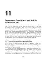
The TCAP and the MAP are “on top” of SS7 (MTP 1–3) and SCCP, the basis
for signaling on all NSS interfaces. Both are dealt with in this one chapter,
because the functionality of the MAP cannot be understood without knowing
about the TCAP. The TCAP, with its Layers 4 through 6 provides the GSM-
specific MAP with a standardized interface to the transmission medium and
to SS7. The clearly separated border between TCAP and MAP, as shown in
Figure 11.1, is in practice more difficult to identify. The transition between the
two layers is rather fuzzy. An essential precondition to understanding MAP is
the study of TCAP. Above MAP, there are the applications themselves, in the
GSM case there are the NSS subsystems HLR, VLR, MSC, and EIR.
11.1 Transaction Capabilities Application Part
TCAP uses SS7 or, more precisely, the SCCP, as shown in Figure 11.1.
The TCAP protocol is, to some extent, the most important piece of the proto-
col stack for GSM or any other mobile system, because it provides the core
functionality to support roaming.
Like the SCCP, TCAP is not restricted to being used by only mobile serv-
ices but is utilized by many other applications for database access and similar
tasks. In that respect, TCAP is different from all previously presented proto-
cols. TCAP allows its users to access databases and switching exchanges via the
worldwide SS7 network and to invoke services or modify parameters. That does
185
not exclude TCAP from being used as a platform for pure data transfer, as in
GSM, after an inter-MSC handover.
TCAP is the typical implementation of the OSI layers 4 through 6. In
that function, it allows integration of some translation functionality into a
message, for instance, to provide a means for users of a transaction to discuss or
synchronize on an application protocol. An example of this is the GSM net-
works of Phase 1 and Phase 2, which come with different sets of features.
Therefore, those GSM networks need to exchange some information in order
to synchronize the feature sets and the respective protocol elements. TCAP
provides that functionality.
Figure 11.2 illustrates a generic communication process via TCAP,
where, initially, both partners need to agree on the protocol to be used. The
receiving side finds the respective information in the dialog control informa-
tion, which in TCAP is called the dialog portion. Figure 11.2 describes the suc-
cessful case only. Figure 11.2 separates the parameter part which in TCAP is
called the component portion. The component portion carries the actual user
data. This is MAP traffic in the case of GSM.
11.1.1 Addressing in TCAP
With respect to addressing, TCAP relies completely on the services of the
SCCP. Although ITU does not explicitly exclude alternatives for the future,
SCCP currently is the only platform for TCAP. TCAP uses exclusively the
connectionless services of SCCP (PCs 0 and 1). The consequence is that
SCCP-UDT messages are the only candidates for the transport of TCAP
186 GSM Networks: Protocols, Terminology, and Implementation
TCAP
SCCP
MAP
HLR EIR
Layer 4–6
Layer 7
Layer 3
VLR
MSC
{
Figure 11.1 Positioning of MAP and TCAP in the SS7 protocol stack.
messages. The sender of a TCAP message directly addresses the destination via
the SCCP. The SCCP routes the message via STPs, where the actual path lies
in the discretion of the SCCP.
Consider the example of addressing in TCAP/SCCP in the context of a
scenario where the MSC and the HLR communicate. Figure 11.3 shows the
SCCP header of a TCAP BEGIN message, where an MSC in Australia accesses
an HLR in Germany. Both sender and addressee are identified by the global
title. Consequently, the MSC in Australia uses the ISDN number of the HLR
in Germany for addressing.
11.1.2 The Internal Structure of TCAP
TCAP can be separated into two parts or layers, as shown in Figure 11.4.
•
The transaction layer in OSI Layer 4 deals with setting up and main-
taining an end-to-end communication. It expects sufficient informa-
tion from its user about the sender and addressee of a message. As
shown in the example in Section 11.1.1, that value is not used by
TCAP itself but passed to the SCCP for addressing. In most cases, the
transaction layer assigns to a process an additional TCAP-internal
Transaction Capabilities and Mobile Application Part
187
MAP
user
MAP
user
Parameter
Dialog control
Parameter
Content of the dialog control:
"Parameters are encrypted and shall be
processed according to protocol XYZ.
Is this protocol and its version OK?"
Yes, the protocol is OK.
Continuation
Dialog control
Figure 11.2 The (optional) dialog at the begin of a communication via TCAP.
188 GSM Networks: Protocols, Terminology, and Implementation
All TCAP messages are transported in SCCP messages of the type UDT.
Hence, TCAP uses the "connectionless" services of SCCP, only. In other
words, only the protocol classes 0 and 1 are used.
Called a subsystem in this example, it is a GSM-HLR
in Germany (more precisely in the "D1" network).
This message is sent by a GSM-MSC
in Australia ( 61) / (operator OPTUS).+=
TCAP message type
UNITDATA
Protocol Class
message handling:0=nospecial options
protocol class : 0
Called Party Address
reserved for national use : 0
routing indicator : routing based on global title
global title indicator:4=global title includes translation
type,numbering plan,encoding scheme and nature of address indicator
SSN indicator : address contains a subsystem number
point code indicator : address contains no signalling point code
subsystem number:6=GSM-HLR
translation type : 0
numbering plan:1=ISDN/telep. numb. plan (recom. E.163 and E.164)
encoding scheme:2=BCD, even number of digits
nature of address indicator:4=international number
address information : 49171041056
Calling Party Address
reserved for national use : 0
routing indicator : routing based on global title
global title indicator:4=global title incl. transl. type,numbering
plan,encoding scheme and nature of address indicator
SSN indicator : address contains a subsystem number
point code indicator : address contains no signaling point code
subsystem number:8=GSM-MSC
translation type : 0
numbering plan:1=ISDN/telep. numb. plan (recom. E.163 and E.164)
encoding scheme:1=BCD, odd number of digits
nature of address indicator:4=international number
address information : 614187067000
BEGIN
Figure 11.3 Important information in the SCCP header of a TCAP message.
Component-layer
Transaction-layer
MAP (mobile application part)
Address information for
the transaction layer
APDU (application protocol data unit)
for the component layer
{
TCAP
Figure 11.4 Separation of TCAP into component and transaction layers and its communica-
tion with MAP.
identifier, the transaction ID, which is comparable to SLR and DLR of
the connection-oriented mode of the SCCP.
•
The component layer in the OSI Layers 5 and 6 is responsible for syn-
chronization and coordination of a communication. It also provides a
uniform data interface to its users, represented by the application pro-
tocol data unit (APDU). In TCAP, APDUs are also referred to as com-
ponents. They transport the payload, which MAP and the component
layer exchange.
11.1.3 Coding of Parameters and Data in TCAP
One of TCAP’s major advantages is its flexibility, which allows for processing
of all kinds of parameter types and data formats. Take this example: TCAP
(equals a shipping company) transports data (goods) of all kinds (pets, dishes,
bulldozer, etc.). More technically speaking,
•
TCAP has to be able to process length indicators from one byte to sev-
eral thousands of bytes. That requires that a sufficiently large area is
reserved for length indicators.
•
It must be possible to distinguish among various parameter types.
Parameter types are of little significance for the lower layers of the OSI
Reference Model. In contrast, OSI Layer 6—in this case, TCAP—has
the task of distinguishing and preprocessing the data for Layer 7
(MAP).
Examples for parameter types are:
•
Strings (i.e., a combination of characters, e.g., “the GSM system”);
•
Integer numbers (0, 1, 2, 3, …);
•
Real numbers (π = 3.14159…).
Recommendations ITU X.208 and X.209 provide a complete definition
of the coding of the various parameter types in ASN.1. GSM uses only a subset
of those parameter types (which will be described later). There are some practi-
cal limitations with respect to the coding of parameters and length that are a
consequence of the limited capacity of the data field of a UDT message (maxi-
mum 255 bytes).
In general, all data and message parts in TCAP are coded according to the
same scheme (Figure 11.5), and there is no distinction between mandatory and
Transaction Capabilities and Mobile Application Part
189
optional parameters. Every message starts with a TAG, which is an identifier,
followed by a length indicator. The TAG indicates the data type of the follow-
ing content.
•
TAG: type, classification;
•
Length: length of the content field;
•
Content: The actual information.
Note that the field “content” itself also may consist of a number of TAGs,
length, and content fields, which then results in an interlaced, overall structure.
That can lead to a confusing structure in which significant space is consumed
by type and length indicators.
Note further that the TAG field and the length indicator can be format-
ted in different ways, whereby the actual format is derived from the coded
information and the application in use. This is more closely examined in the
next section.
11.1.3.1 Formatting of the TAG Field
The TAG field is used to identify the data part, in which distinctions have to be
made among data classes, formats, and types. For that reason, the TAG field
itself is composed of three parts that provide the information. Note that the
length indication and bit information in Figure 11.6 refer to a TAG with a
length of 1 byte, only.
The meaning of the various fields is as follows:
190 GSM Networks: Protocols, Terminology, and Implementation
TAG
Length
Content
Figure 11.5 Coding of data in TCAP.
2 bit
5 bit
76543210
Class
Format
TAG value
MSB LSB
1 bit
Figure 11.6 Format of TAG field (short form with length of 1 byte).
Class
Class defines the data type. Four classes need to be distinguished and are listed
in Table 11.1. (The definitions provided in Table 11.1 are taken from ITU
X.208.)
Format
Format distinguishes between two possible formats. It has to be noted that the
distinction is valid only on the interface between MAP and TCAP.
•
Format = 0
bin
: The data field contains a primitive, which means that
the parameter is not further partitioned.
•
Format = 1
bin
: The data field contains a constructor. Here, the TAG
field is only a generic reference for the parameters that follow in the
data field, which again are constructors or primitives.
TAG Value
The TAG value indicates to the recipient what kind of parameter type the data
field carries. ITU provides a number of proposals that are mandatory within
ITU applications (i.e., the universal, applicationwide, and context-specific data
classes). The private-use data class can be used for proprietary data types.
11.1.3.2 Primitive Versus Constructor
The difference between a primitive, a single parameter and a constructor, and a
collection of parameters is valid only in the context of formatting in TCAP. It
can be explained by the example of transmitting an IMSI.
Transaction Capabilities and Mobile Application Part
191
Table 11.1
Classification of Data in TCAP
Value (Bin) Class, Explanation
00 Universal: Universal data types are specified in X.208. These data types are inde-
pendent of an application, and all users of SS7 have to be able to recognize them.
01 Applicationwide: Valid only within an ITU Recommendation (e.g., TCAP message
types and data types).
10 Context-specific: Valid only in an ITU application (e.g., MAP data types).
11 Private use: Network- or service-provider-specific data types, which will never be
assigned by ISO or ITU.
The IMSI is a constructor per definition. It consists of MCC, MNC, and
MSIN (mobile sunbscriber identification number), as presented in Figure 11.7.
In TCAP, the IMSI can be coded in two ways. Although the second way
of representation may seem unusual, it still demonstrates the alternatives.
•
If the IMSI is coded as a primitive, TCAP does not distinguish among
MNC, MCC, and MSIN. The complete IMSI is coded as shown in
Figure 11.8. The format value 0 indicates that this is a primitive and
thus a single parameter message.
•
If, however, the individual parameters of the IMSI are coded sepa-
rately as individual parameters, then a constructor is used for the
IMSI where the parameters MCC, MNC, and MSIN are the primi-
tives (Figure 11.9). Note that the fill digit F is required for the MCC,
because the MCC has a length of 3 bytes (uneven number of bytes).
The following remarks are given: (1) Because the MCC, MNC, and
192 GSM Networks: Protocols, Terminology, and Implementation
3 digits 2 digits 10 digits
MCC MNC MSIN
Figure 11.7 The IMSI.
.... 80 08 IMSI ...
<= MCC
<= MNC
<= MSIN
z.B. 262 02 9876543219F
Length of the IMSI 8 bytes=
TAG value of the IMSI as assigned by the application.
in this case '0'
Format 0 Primitive, content (IMSI) is not fragmented==>
Classification of this parameter 10 "context specific"==>
bin
10 0 00000
bin
Figure 11.8 Coding of an IMSI as a primitive (with TAG and length indicator).
MSIN are formatted as separate parameters, each requires its own
TAG and length indicator, and (2) the overall length of the message
increases by 6 bytes, compared to the first version.
11.1.3.3 More Options for Coding the TAG
Expansion
Let us, once more, come back to Figure 11.6. The 5-bit of the
TAG value field allows addressing of 31 different parameter types. That may
not be enough for certain applications. Furthermore, ASN.1 has predefined
most of the values (refer to the Glossary).
In addition, it may be necessary for the internal purposes of an applica-
tion to assign a TAG value outside that value range (0–31).
The solution to the problem consists of the extension of the TAG to
any necessary length. To do so, a special method is used, which is illustrated in
Figure 11.11 and explained as follows.
•
A TAG with a length of 1 byte is used for all TAG values smaller than
31
dez
. The TAG value is binary coded. Hence, the maximum TAG
value is 30
dez
and its binary representation is 11110
bin
.
Transaction Capabilities and Mobile Application Part
193
Total length of IMSI MCC MNC MSIN=++
TAG for MCC (context specific, primitive, TAG value '1')=
Length indication for the individual elements MCC, MNC, and MSIN
TAG for MNC TAG for MSIN
TAG value of the IMSI as assigned by the application,
in this case 0
Format 1; Constructor, content (IMSI) is fragmented=
Classification of this parameter 10 ; "context specific"=
bin
10 1 00000
bin
A0 0E 81 02 26 2F 82 01 02 83 05 98 76 54 32 19
Figure 11.9 Coding of an IMSI as a constructor (with TAGs and length indicators).
•
If the TAG value exceeds 30
dez
, then more than one octet is required to
code that value. Therefore, the value 11111
bin
for the first byte of the
TAG is reserved to indicate that the TAG is extended. In this way of
coding, bits 0 through 6 of the following octets contain the actual
value of the TAG. To be more precise, bits 0 through 6 represent the
TAG value, while bit 7 always indicates whether another octet with
a TAG value field follows. If bit 7 is set to 1, the next octet also
contains TAG information; if bit 7 is set to 0, the TAG ends with this
octet. Bit 6 of the second octet is the most significant bit (MSB), while
bit 0 of the last octet represents the least significant bit (LSB).
Data Type Octetstring
Two variants of TAG coding have been presented, the
“short” and the “long” versions, which can be assigned by the user based on
data type and TAG value. GSM uses yet another TAG borrowed from ASN.1.
This data type is the octetstring, which is always used as the TAG when the
data type does not require that an explicit identification be provided.
Data type octetstring has a fixed TAG value of 00100
bin
, which is the rep-
resentation of 4
dez
.
For the class = universal = 00 and format = primitive = 0, the result for
the TAG is 04
hex
.
The data type octetstring was defined by ITU, in particular, to transport
strings, where the individual characters are ASCII coded. The Glossary pro-
vides a complete list of all variable types and the assigned TAGs.
An example of “GSM” coded as octetstring in shown in Figure 11.10.
Note a peculiarity of MAP when it uses the octetstring TAG. When
numbers need to be transmitted, the respective digits are not coded in ASCII.
Figure 11.11 illustrates the various formats for TAG and length
indicators.
194 GSM Networks: Protocols, Terminology, and Implementation
TAG
Length
GS
M
ASCII ASCII ASCII
04 03
47
53
4D
Figure 11.10 Format of octetstring.
TransactionCapabilitiesandMobileApplicationPart
195
TAG Length Data
Data
Class
For-
mat
TAG value
76543210bit
Class
For-
mat
11111
76543210bit
76543210bit
1 TAG value (high)
76543210bit
1 TAG value
76543210bit
0 TAG value (low)
76543210bit
0 Length
76543210bit
10000000
TAG 30>=>
dec
Length 128<=>
dec
Length 127>=>
dec
Length not determined =>
TAG 31<=>
dec
76543210bit
1
Number of length bytes (N)
EOC 00 00=
76543210bit
Length (high)
Byte 1
76543210bit
Length
76543210bit
Length (low)
Byte N
Figure 11.11 Various formats for TAG and length indicators in TCAP. Note that bit 0 is always sent first, despite the information about the direc-
tion, right to left.
11.1.3.4 Presentation of the Length Indicator
Problems similar to those described for the coding of the TAG arise in the cod-
ing of the length of a message or a parameter. The theoretical limit for coding
the length field with just 1 byte is 255 bytes. For all practical purposes, that
value would be suitable for the time being, because SCCP UDT messages are
limited to 255 bytes. However, to be safe in the future and allow for additional
applications, a solution was needed that allowed the coding of a field of any
necessary (arbitrary) length.
Another requirement was that fields of undefined length be allowed, at
least for constructor parameters, where MAP possibly does not know the actual
length. Therefore, three different representations needed to be distinguished
(see Figure 11.11).
•
For “small” length (less than 128 bytes), the length indicator field is
1 byte long. Only bits 0 through 6 are used, which allows coding of
values between 0 and 127
dez
(0111 1111
bin
). Bit 7 is always zero; hence,
the limit of 255 cannot be reached.
•
For a “large” length (greater than 127 bytes), the length indicator field
needs to be extended by the necessary number of bytes. For that pur-
pose, bit 7 is set to 1 and bits 0 through 6 then indicate the number of
bytes to follow, which carry length information. For example, when
the first byte of the length indicator field is coded as 1000 0111
bin
,
then 7 bytes (111
bin
= 7) of length information will follow, for a total
of 8 bytes of length information.
•
For an undefined length, the length indicator field is 1 byte long and is
fix-coded with 80
hex
. Here, bits 0 through 6 are all of 0 value and bit 7
is set to 1. However, the end of a parameter with undefined length
needs to be indicated, too. For that purpose, a special end mark, the
end of contents (EOC), is added. The EOC consists of 2 bytes, coded
with all zeroes. Note that an undefined length indication may be used
only for constructor parameters.
11.1.3.5 “Large” TAG and Length Indicator
In this example, a parameter needs to be coded for the transmission via TCAP.
TAG and length are as follows:
TAG type = 2222
dez
= 08AE
hex
= 0000 1000 1010 1110
bin
length = 3333
dez
= 0D05
hex
= 0000 1101 0000 0101
bin
196 GSM Networks: Protocols, Terminology, and Implementation
This represents a parameter of class “constructor” with the format “context spe-
cific.” In both cases, 1 byte is not enough to code the particular fields. The
value for TAG is greater than 30 and the length is greater than 127. For that
reason the expanded form has to be applied.
The TAG
Three bytes are necessary to represent the TAG, as shown in Figure 11.12(a).
Byte 1 is used to define class and format, while bytes 2 and 3 contain the actual
TAG value.
•
The value for class is 10
bin
= context specific.
•
The value for format (F) is 1
bin
= constructor.
•
The value for TAG of the first byte is 11111
bin
and indicates that the
TAG is expanded.
•
The actual TAG value of 0000 1000 1010 1110
bin
needs to be coded
within bytes 2 and 3 and then be inserted right-aligned. Bit 7 may not
be used and leading zeros are omitted.
Coding of the type TAG, therefore, is BF 91 2E
hex
.
The Length Indicator
The length indicator itself requires 2 bytes (0D05
hex
). Together with the
first byte (to indicate an extended length field), that totals 3 bytes, as shown in
Figure 11.12(b):
Transaction Capabilities and Mobile Application Part
197
Byte 1 Byte 2 Byte 3
Class F TAG extended
bit
76543210
10111111
10111111
BF
E
TAG value (high)
bit
76543210
1XXXXXXX
1001
0 001
91
E
TAG value (low)
bit
76543210
0XXXXXXX
0
010 1 110
2E
11.12(a) Coding a large TAG.
•
Bit seven of the first byte is the extension mark and needs to be set to 1.
•
Because the actual length requires 2 additional bytes, bits 0–6 have to
be coded with a value of 000 0010
bin
= 2.
•
Now, the value for the length (0D05
hex
) is inserted into bytes 2 and 3,
starting from the right.
Coding of the length, therefore, is 82 0D 05
hex
.
11.1.4 TCAP Messages Used in GSM
ITU-T, in its Recommendations Q.772 and Q.773, has defined five TCAP
messages, of which GSM uses four. The four messages used in GSM are illus-
trated in Figure 11.13. The white areas in Figure 11.13 are optional parts; the
mandatory parts are shaded.
Table 11.2 provides details on the various TCAP messages. Note that the
messages form only the transport container for the MAP content.
11.1.4.1 The Dialog Portion
The dialog control of TCAP messages was mentioned at the beginning of this
chapter. The dialog control is, together with some further information, part of
the optional dialog portion of a TCAP message (see Figure 11.15).
Structured Versus Unstructured Dialog
The term dialog portion has a meaning different from that of the term dialog.A
dialog refers to the whole communication process of exchanging information
between users. One has to distinguish between an unstructured dialog and a
structured dialog. GSM uses the services of the structured dialog only. For that
198 GSM Networks: Protocols, Terminology, and Implementation
Byte 1 Byte 2 Byte 3
Number of subsequent bytes Length indicator (high) Length indicator (low)
bit
76543210
10000010
10000010
82
bit
76543210
XXXXXXXX
00001101
0D
bit
76543210
XXXXXXXX
00000101
05
E
Figure 11.12(b) Coding a large length indication.
reason, unstructured dialog will not be dealt with in more detail. However, it
should be mentioned that unstructured dialog, when used, is transmitted in a
Transaction Capabilities and Mobile Application Part
199
BEGin/MT 62=
CONtinue/MT 65=
Length
Length
Length
Length
Dialog portion
Dialog portion
Component portion
Component portion
OTI
OTI
Messagetypetag=>Messagetypetag=>
Messagetypetag=>
Originatingtransaction
identifiertag=>
Originatingtransaction
identifiertag=>
Originatingtransaction
identifiertag=>
Originatingtransaction
identifier
Originatingtransaction
identifier
1–4 byte
}
48
48
MT
MT
Dialog port.
Dialog port.
Component portion
DTI
Destinationtransaction
identifiertag=>
Destinationtransaction
identifier
Length
49
END/MT 64=
DTI
Destinationtransaction
identifier
Length Length
49 MT
ABorT/MT 67=
DTI
Messagetypetag=>
P-Abortcause=>
P-Abortcausetag=>
Destinationtransaction
identifiertag=>
Destinationtransaction
identifier
Length Length
49
[?]
4A MT
0 Unrecognized message type
1 Unrecognized transaction ID
2 Badly formatted transaction portion
3 Incorrect transaction portion
4 Resource limitation
=>
=>
=>
=>
=>
1–4 byte
}
1–4 byte
}
1–4 byte
}
1–4 byte
}
Figure 11.13 TCAP messages used in GSM.