CARD HOLDER - Pro/ENGINEER Wildfire 3.0
Bạn đang xem bản rút gọn của tài liệu. Xem và tải ngay bản đầy đủ của tài liệu tại đây (1.69 MB, 44 trang )
ME-430 Introduction to Computer Aided Design
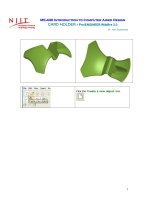
CARD HOLDER - Pro/ENGINEER Wildfire 3.0
Dr. Herli Surjanhata
Pick the Create a new object icon
.
1
Type in card_holder for the name
of the new part.
Un-check Use default template.
The default units of Pro/E is
inlbs_part_solid.
The units of the bracket are
mm, so select
mmns_part_solid.
Click OK since the part will have
millimeters units.
Click OK in the New dialog box.
The default datum planes
appear in the graphics area.
2
CREATE A REVOLVED BASE FEATURE
Create the base feature – Pick the
.
Revolve Tool icon
In the dashboard, click the
option.
Click on Define.
Pick Right datum plane as Sketch Plane.
For Sketch Orientation Reference, select Top datum plane as Orientation.
3
Then click the Sketch button
.
Click the small downward
icon to expand, and pick
.
Draw vertical centerline through coordinate system. The
centerline is used as axis of revolution.
4
Use line tool icon
figure below.
and arc tool
Click
to create a section to be rovelved – see
to dimension the section as shown below.
If necessary, click
shown.
Click
to modify the dimension as
.
Accept 360 degree rotational angle.
5
Click
.
Click
and select Standard
Orientation.
CREATE THREE CIRCULAR CUTS OF THE BASE FEATURE
Pick the Extrude Tool icon
.
6
.
Pick Remove Material option
Select Thru All option
extrusion depth
for the
In the dashboard, click
option.
the
Click on Define.
Pick TOP datum plane as Sketch Plane.
For Sketch Orientation Reference,
accept default RIGHT datum plane as
Right Orientation.
Then click the Sketch button
.
7
Sketch the following circular section with the proper dimensions shown below.
Click on
when done with the section.
Click on
cut.
to complete the circular
Mirror the previous cut.
Be sure to select the cut feature – in this case, Extrude
2.
8
Select the Mirror Tool
.
Pick the RIGHT datum plane as the mirror plane.
Click on
to complete the mirroring process. The resulted object is shown below.
9
Create another (last) cut.
Pick the Extrude Tool icon
.
10
.
Pick Remove Material option
Select Thru All option
extrusion depth
for the
Pick TOP datum plane as Sketch Plane. For Sketch Orientation Reference,
accept default RIGHT datum plane as Right Orientation.
Then click the Sketch button
.
Sketch the following circular section with the follwing dimensions shown below.
11
Click on
when done with the section.
Click on
cut.
to complete the circular
12
CREATE SIDE CUT
Pick the Extrude Tool icon
.
Click the Remove Material icon
.
Select Thru All option
13
Click Options tab,
Select Through All for Side
1 and Side 2.
Click
.
to
Click on
define sketch section for cut.
Pick RIGHT as sketching plane, and TOP
datum plane as Top Orientation.
Click Sketch button.
Sketch the section as shown below.
14
Click
. Then Click
.
15
CREATE A SWEPT BLEND FEATURE
Pick a Sketch Tool icon
.
Pick the inclined surface as shown as the sketching plane, and select RIGHT datum
plane as Reference, then choose Right in the Orientation box.
16
Pick this surface as
sketching plane.
Click
display.
to change the display to Hidden Line
Select the filter option, and choose
Edge.
Pick the edge as shown below.
17
Pick this edge
as reference
Close the References dialog box.
Draw a vertical center line through the coordinate
system using
Use line tool
below.
.
to draw the horizontal line as shown
Note that the horizontal line is symmetry with respect to
the centerline.
If necessary, click on
and set the Symmetry
constraint by selecting
. Pick first end point of the
line, pick the centerline, and then select second end point
of line.
18
The resulted line is shown below. Be sure to dimension the line accordingly.
Draw this centerline for
symmetry.
Sketch the conic arc using Conic tool
.
Dimension the arc as shown below.
The resulted section is shown below.
19
Click
to finish the first datum curve.
Next create the second conical datum curve at the bottom of the part. This datum
curve is located at TOP datum plane.
Pick a Sketch Tool icon
.
20
Pick the TOP datum plane as the sketching plane, and select RIGHT datum plane as
Reference, then choose Right in the Orientation box.
Repeat the same procedure and draw the following section.
21
Click
to finish the first datum curve.
Cerate two datum points at the intersection between
Select Datum Point tool
.
Pick the conic arc, and while pressing down Ctrl key, pick the RIGHT datum plane.
A new datum point PNT0 is created at the intersection.
22
To create another Datum Point, click on
New Point.
Pick the conic arc located at the bottom, and while pressing down Ctrl key, pick the
RIGHT datum plane.
The next datum point PNT1 is created at the intersection.
23
Click OK.
24
Two datum points are created.
Next create another curve that will be used as trajectory for the sweep. The datum
curve is an arc connecting PNT1 and PNT0.
Pick a Sketch Tool icon
.
Pick the RIGHT datum plane as the sketching plane, and select TOP datum plane as
Reference, and then choose Top in the Orientation box.
25