Light—Science & Magic- P2
Bạn đang xem bản rút gọn của tài liệu. Xem và tải ngay bản đầy đủ của tài liệu tại đây (5.51 MB, 50 trang )
LIGHT—SCIENCE & MAGIC
38
So, with all that in mind, it is easy to see why the three cam-
eras see such a difference in the brightness of the mirror. Those
positioned on each side receive no reflected light rays. From
their viewpoint, the mirror appears black. None of the rays
from the light source is reflected in their direction because they
are not viewing the mirror from the one (and only) angle in
which the direct reflection of the light source can happen.
However, the camera that is directly in line with the reflection
sees a spot in the mirror as bright as the light source itself. This is
because the angle from its position to the glass surface is the same
as the angle from the light source to the glass surface. Again, no
real subject produces a perfect direct reflection. Brightly polished
metal, water, or glass may nearly do so, however.
Breaking the Inverse Square Law?
Did it alarm you to read that the camera that sees the direct
reflection will record an image “as bright as the light source”?
How do we know how bright the direct reflection will be if we
do not even know how far away the light source is?
We do not need to know how far away the source is. The
brightness of the image of a direct reflection is the same regard-
less of the distance from the source. This principle seems to
stand in flagrant defiance of the inverse square law, but an easy
experiment will show why it does not.
You can prove this to yourself, if you like, by positioning a
mirror so that you can see a lamp reflected in it. If you move
the mirror closer to the lamp, it will be apparent to your eye
that the brightness of the lamp remains constant.
Notice, however, that the size of the reflection of the lamp
does change. This change in size keeps the inverse square law
from being violated. If we move the lamp to half the distance,
the mirror will reflect four times as much light, just as the
inverse square law predicts, but the image of the reflection cov-
ers four times the area. So that image still has the same bright-
ness in the picture. As a concrete analogy, if we spread four
times the butter on a piece of bread of four times the area, the
thickness of the layer of butter stays the same.
Now we will look at a photograph of the scene in the previ-
ous diagram. Once again, we will begin with a high-contrast light
source. Figure 3.5 has a mirror instead of the earlier newspaper.
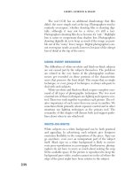
Here we see two indications that the light source is small. Once
again, the shadows are hard. Also, we can tell that the source is
Hunter-Ch03.qxd 9/1/07 2:35 PM Page 38
Please purchase PDF Split-Merge on www.verypdf.com to remove this watermark.
MANAGEMENT OF REFLECTION AND FAMILY OF ANGLES
39
small because we can see it reflected in the mirror. Because the
image of the light source is visible, we can easily anticipate the
effect of an increase in the size of the light. This allows us to plan
the size of the highlights on polished surfaces.
Now look at Figure 3.6. Once again, the large, low-contrast
light source produces softer shadows. The picture is more
pleasing, but that is not the important aspect. More important
is the fact that the reflected image of the large light source
completely fills the mirror. In other words, the larger light
source fills the family of angles that causes direct reflection.
This family of angles is one of the most useful concepts in
photographic lighting. We will discuss that family in detail.
THE FAMILY OF ANGLES
Our previous diagrams have been concerned with only a single
point on a reflective surface. In reality, however, each surface is
3.5
Two clues tell us this picture was made with a
small light source: hard shadows and the size of the
reflection in the mirror.
3.6
A larger light softens the shadow. More
important, the reflection of the light now completely fills
the mirror. This is because the light we used this time
was large enough to fill the family of angles that causes
direct reflection.
Hunter-Ch03.qxd 9/1/07 2:35 PM Page 39
Please purchase PDF Split-Merge on www.verypdf.com to remove this watermark.
LIGHT—SCIENCE & MAGIC
40
made up of an infinite number of points. A viewer looking at a
surface sees each of these points at a slightly different angle.
Taken together, these different angles make up the family of
angles that produces direct reflection.
In theory, we could also talk about the family of angles that
produces diffuse reflection. However, such an idea would be
meaningless because diffuse reflection can come from a light
source at any angle. Therefore, when we use the phrase family
of angles we will always mean those angles that produce direct
reflection.
This family of angles is important to photographers because it
determines where we should place our lights. We know that light
rays will always reflect from a polished surface, such as metal or
glass, at the same angle as that at which they strike it. So we can
easily determine where the family of angles is located, relative to
the camera and the light source. This allows us to control if and
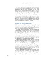
where any direct reflection will appear in our picture. Figure 3.7
shows the effect of lights located both inside and outside this
family of angles. As you can see from Figure 3.7, any light posi-
tioned within the family of angles will produce a direct reflec-
tion. A light placed anywhere else will not. Consequently, any
light positioned outside of the family of angles will not light a
mirror-like subject at all, at least as far as the camera can see.
F
a
m
i
l
y
o
f
A
n
g
l
e
s
3.7
The light positioned within
the family of angles will produce
direct reflection. The other light,
outside the family of angles, will
not.
Hunter-Ch03.qxd 9/1/07 2:35 PM Page 40
Please purchase PDF Split-Merge on www.verypdf.com to remove this watermark.
MANAGEMENT OF REFLECTION AND FAMILY OF ANGLES
41
Photographers sometimes want to see direct reflection from
most of the surface of a mirror-like subject. This requires that
they use (or find in nature) a light large enough to fill the family
of angles. In other scenes, they do not want to see any direct
reflection at all on the subject. In those instances, they must
place both the camera and the light so that the light source is not
located within the family of angles. We will use this principle
repeatedly in the coming chapters.
POLARIZED DIRECT REFLECTION
A polarized direct reflection is so similar to an ordinary direct
reflection that photographers often treat them as the same.
However, these reflections offer photographers several special-
ized techniques and tools for dealing with them.
Like the direct reflection, only one viewer in Figure 3.8 will
see the reflection. Unlike the direct reflection, an image of the
polarized reflection is always substantially dimmer than a photo-
graph of the light source itself. A perfectly polarized direct reflec-
tion is exactly half as bright as an unpolarized one (provided the
light source itself is not polarized). However, because polariza-
tion is inevitably accompanied by absorption, the reflections we
see in the scene are more likely to be much dimmer than that. To
3.8
Polarized direct reflection
looks like unpolarized direct
reflection, only dimmer.
Hunter-Ch03.qxd 9/1/07 2:35 PM Page 41
Please purchase PDF Split-Merge on www.verypdf.com to remove this watermark.
LIGHT—SCIENCE & MAGIC
42
see why polarized reflection cannot be as bright as an unpolar-
ized direct reflection, we need to know a bit about polarized
light.
We have seen that the electromagnetic field fluctuates around
a moving photon. In Figure 3.9 we have represented this fluctu-
ating field as a jump rope being swung between two children.
One child is spinning the rope while the other simply holds it.
Now, let’s put up a picket fence between the children, as
shown in Figure 3.10. The rope now bounces up and down
instead of swinging in an arc. This bouncing rope resembles the
electromagnetic field along the path of a photon of polarized light.
Molecules in a polarizing filter block the oscillation of the
light energy in one direction, just as the picket fence does to the
oscillating energy of the jump rope. The molecular structure of
some reflecting surfaces also blocks part of the energy of the
photon in the same manner. We see such a photon as a polarized
reflection or glare. Now suppose, not being satisfied with elimi-
nating just a part of the children’s play, we install a horizontal
fence in front of the first, as shown in Figure 3.11.
3.9
The oscillating
electromagnetic field around a
photon represented as a jump
rope. The child on the left is
spinning the rope while the one
on the right holds on.
3.10
When the children spin
the rope through the picket
fence, it bounces up and down
instead of spinning in an arc.
A polarizing filter blocks the
oscillation of light energy the
same way.
Hunter-Ch03.qxd 9/1/07 2:35 PM Page 42
Please purchase PDF Split-Merge on www.verypdf.com to remove this watermark.
MANAGEMENT OF REFLECTION AND FAMILY OF ANGLES
43
With the second fence in place, if one child spins the rope,
the other sees no rope movement at all. The crossed picket
fences block the transmission of energy from one end of the
rope to the other. Crossing the axes of two polarizing filters
blocks the transmission of light, just as the two picket fences do
with rope energy. Figure 3.12 shows the result. Where the
polarizers overlap with their axes perpendicular, none of the
type is visible on the page. The transmission of light reflected
from the page to the camera has been completely blocked.
A lake, painted metal, glossy wood, or plastic can all produce
polarized reflection. Like the other types of reflection, the
3.11
Because we’ve added a
horizontal fence to the first,
when one child spins the rope,
the other will see no movement.
3.12
The two overlapping
polarizers have their axes
perpendicular. They block light
just as the two fences did with
the energy of the jump rope.
Hunter-Ch03.qxd 9/1/07 2:36 PM Page 43
Please purchase PDF Split-Merge on www.verypdf.com to remove this watermark.
LIGHT—SCIENCE & MAGIC
44
polarization is not perfect. Some diffuse reflection and some
unpolarized direct reflection are mixed with the glare. Glossy
subjects produce a greater amount of polarized reflection, but
even matte surfaces produce a certain amount.
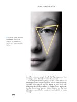
Polarized direct reflection is more visible if the subject is
black or transparent. Black and transparent subjects do not nec-
essarily produce stronger direct reflections than white ones.
Instead, they produce weaker diffuse reflection, making it easier
to see the direct reflection. This is why you saw the change in
apparent brightness of the black objects, but not of the white
ones, when you walked around your room a while ago.
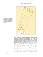
Glossy black plastic can show us enough polarized reflection
to make a good example. The scene in Figure 3.13 includes a
black plastic mask and a feather on a sheet of glossy black plas-
tic. We used the same camera and light position as in the pic-
tures of the newspaper and the makeup mirror. You can tell by
the size of the reflections that we used a large light source.
Both the mask and the plastic sheet produce nearly perfect
polarized reflection. From this angle, glossy plastic produces
almost no unpolarized direct reflection; black things never
produce much diffuse reflection. However, the feather behaves
quite differently. It produces almost nothing but diffuse
reflection.
The light source was large enough to fill the family of angles
defined by the plastic sheet, creating direct reflection over the
entire surface. The same light was large enough to fill only part
of the family of angles defined by the mask. We know this
because of the highlights we see only on the front of the mask.
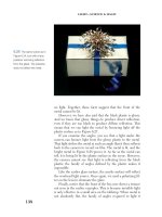
Now look at Figure 3.14. We made it with the same arrange-
ment used in the previous picture, but now we’ve placed a
polarizing filter over the camera lens. Because polarized reflec-
tion was almost the only reflection from the black plastic in
Figure 3.14, and because the polarizing filter blocks glare, little
of the light reflected from them reached the camera. As a
result, the plastic now looks black.
We did have to open our aperture by about two stops to
compensate for the neutral density of the polarizing filter. How
do you know that we did not accidentally miscalculate the expo-
sure? (Maybe we did so deliberately, just to get the image dark
enough to prove our point.) The feather proves that we did not.
The polarizer did not block the diffuse reflection from the
feather. So, with accurate exposure compensation, the feather
is about the same light gray in both pictures.
Hunter-Ch03.qxd 9/1/07 2:36 PM Page 44
Please purchase PDF Split-Merge on www.verypdf.com to remove this watermark.
MANAGEMENT OF REFLECTION AND FAMILY OF ANGLES
45
Is It Polarized Reflection or Ordinary Direct
Reflection?
Polarized and unpolarized direct reflections often have similar
appearance. Photographers, out of need or curiosity, may want
to distinguish one from the other.
We know that direct reflection appears as bright as the light
source, whereas polarized direct reflection appears dimmer.
However, brightness alone will not tell us which is which.
Remember that real subjects produce a mixture of reflection
types. A surface that seems to have polarized reflection may
actually have weak direct, plus some diffuse, reflection.
Here are a few guidelines that tend to tell us whether a
direct reflection is polarized:
●
If the surface is made of a material that conducts electricity
(metal is the most common example), its reflection is likely to
be unpolarized. Electrical insulators such as plastic, glass,
and ceramics are more likely to produce polarized reflection.
3.13
The glossy black plastic sheet and mask
produce almost nothing but polarized direct reflection.
The feather gives off almost nothing but diffuse
reflection.
3.14
A polarizer over the camera lens blocks the
polarized direct reflection. Only the feather, which gives
off diffuse reflection, is easily visible.
Hunter-Ch03.qxd 9/1/07 2:36 PM Page 45
Please purchase PDF Split-Merge on www.verypdf.com to remove this watermark.
LIGHT—SCIENCE & MAGIC
46
●
If the surface looks like a mirror—for example, bright
metal—the reflection is likely to be simple direct reflection,
not glare.
●
If the surface does not have a mirror-like appearance—for
example, polished wood or leather—the reflection is more
likely to be polarized if the camera is seeing it at an angle of
40 to 50 degrees. (The exact angle depends on the subject
material.) At other angles, the reflection is more likely to be
unpolarized direct reflection.
●
The conclusive test, however, is the appearance of the sub-
ject through a polarizing filter. If the polarizer eliminates the
reflection, then that reflection is polarized. If, however, the
polarizer has no effect on the suspect reflection, then it is
ordinary direct reflection. If the polarizer reduces the bright-
ness of the reflection but does not eliminate it, then it is a
mixed reflection.
Increasing Polarized Reflection
Most photographers know that polarizers can eliminate polarized reflection they do
not want, but in some scenes we may like the polarized reflection and want even
more of it. In such cases we can use the polarizer to effectively increase the polar-
ized. We do this by rotating the polarizing filter 90 degrees from the orientation
that reduces reflection. The polarized light then passes through easily.
It is important to understand that a polarizer always blocks some unpolarized
light. By doing this, in effect, it becomes a neutral density filter that affects every-
thing except direct reflection. Thus, when we increase the exposure to compen-
sate for the neutral density, the direct reflection is increased even more.
Turning Ordinary Direct Reflection
into Polarized Reflection
Photographers often prefer that a reflection be polarized
reflection so that they can manage it with a polarizing filter
mounted on their camera lens. If the reflection is not glare, the
polarizer on the lens will have no effect except to add neutral
density.
However, placing a polarizing filter over the light source
will turn a direct reflection into polarized reflection. A
polarizer on the camera lens can then manage the reflection
nicely.
Hunter-Ch03.qxd 9/1/07 2:36 PM Page 46
Please purchase PDF Split-Merge on www.verypdf.com to remove this watermark.
MANAGEMENT OF REFLECTION AND FAMILY OF ANGLES
47
Polarized light sources are not restricted to studio lighting.
The open sky often serves as a beautifully functional polarized
light source. Facing the subject from an angle that reflects the
most polarized part of the sky can make the lens polarizing filter
effective. This is why photographers sometimes find polarizing
filters useful on subjects such as bright metal, even though the
filter manufacturer may have told them that polarizers have no
effect on such subjects. In those cases, the subject is reflecting a
polarized source.
APPLYING THE THEORY
Excellent recording of a subject requires more than focusing
the camera properly and exposing the picture accurately. The
subject and the light have a relationship with each other. In a
good photograph, the light is appropriate to the subject and the
subject is appropriate to the light.
The meaning of appropriate is the creative decision of the
photographer. Any decision the photographer makes is likely to
be appropriate if it is guided by understanding and awareness
of how the subject and the light together produce an image.
We decide what type of reflection is important to the sub-
ject and then capitalize on it. In the studio, this means manip-
ulating the light. Outside the studio, it often means getting the
camera position, anticipating the movement of the sun and
clouds, waiting for the right time of day, or otherwise finding
the light that works. In either case, the job is easier for the pho-
tographer who has learned to see what the light is doing and to
imagine what it could do.
Hunter-Ch03.qxd 9/1/07 2:36 PM Page 47
Please purchase PDF Split-Merge on www.verypdf.com to remove this watermark.
48
Hunter-Ch04.qxd 9/1/07 5:07 PM Page 48
Please purchase PDF Split-Merge on www.verypdf.com to remove this watermark.
49
4
Surface Appearances
All surfaces produce diffuse, direct, and polarized reflection in
varying degrees. We see all of these reflections, but we are not
always conscious of all of them.
Years of programming enable our brains to edit the image
of the scene. This editing minimizes reflection that is distract-
ing or trivial to the subject. At the same time, it maximizes
the importance of whatever light is essential to our compre-
hension of the scene. The psychological image in the brain
may be quite different from the photochemical one the eye
actually sees.
A reflection in a shop window may be many times the
brightness of the goods displayed inside. Nevertheless, if we
are interested in the merchandise, then that is what we see, not
the interfering reflection.
But the brain cannot edit an image of an image so effec-
tively. If we photograph the same shop window, without elimi-
nating the surface reflection, then a viewer looking at the
picture may not be able to see through the glass at all.
Psychologists have not completely explained why this differ-
ence exists. Movement certainly has something to do with it, but
not everything. Some visual defects are less disturbing in a
motion picture than they might be in a still photograph, but not
much.
Photographers know that the brain cannot edit an image of
the scene as well as the scene itself. We discovered that fact when
we learned how quickly we could spot defects in our images,
even though we could not see them at all when we carefully
Hunter-Ch04.qxd 9/1/07 5:07 PM Page 49
Please purchase PDF Split-Merge on www.verypdf.com to remove this watermark.
LIGHT—SCIENCE & MAGIC
50
examined the original scene. Unconscious parts of our brain did
us the “service” of editing the scene to delete extraneous and
contradictory data. The viewer becomes fully conscious of the
same details on seeing the picture.
How do pictures reveal things we might never otherwise
notice? This is a question for another book. This book is about
what we need to do about that fact and how to take advantage
of it. When we make a picture we have to consciously do some
of the editing that other observers do unconsciously.
THE PHOTOGRAPHER AS EDITOR
Photographic lighting deals mainly with the extremes: the high-
lights and the shadows. When we are happy with the
appearance of these two, we are likely to be pleased with
the middle range also. Highlight and shadow together reveal
form, shape, and depth. But highlight alone is usually enough
to reveal what the surface of an object is like. In this chapter we
will concern ourselves primarily with highlight and surface.
Most of our example subjects will be flat—two dimensional, or
nearly so. In Chapter 5 we will complicate matters a bit with
three-dimensional subjects and a more detailed discussion of
shadow.
In the last chapter, we saw that all surfaces produce both
diffuse and direct reflections and that some of the direct reflec-
tions are polarized. But most surfaces do not produce an even
mix of these three types of reflections. Some surfaces produce
a great deal more of one than another. The difference in the
amounts of each of these reflections determines what makes
one surface look different from another.
One of the first steps in lighting a scene is to look at the sub-
ject and decide what kind of reflection causes the subject to
appear the way it does. The next step is to position the light, the
subject, and the camera to make the photograph capitalize on
that type of reflection and minimize the others.
When we do this we decide what kind of reflection we want
the viewers to see. Then we engineer the shot to make sure
they see that reflection and not others.
“Position the light” and “engineer the shot” imply moving
light stands around a studio, but we don’t necessarily mean that.
We do exactly the same thing when we pick the camera view-
point, day, and time outside the studio. We will use studio
examples in this chapter simply because they are easy for us to
Hunter-Ch04.qxd 9/1/07 5:07 PM Page 50
Please purchase PDF Split-Merge on www.verypdf.com to remove this watermark.
SURFACE APPEARANCES
51
control to demonstrate the specifics clearly. The principles
apply to any type of photography.
In the rest of this chapter, we will see some examples of sub-
jects that require us to capitalize on each of the basic kinds of
reflections. We will also see what happens when we photograph
reflections that are inappropriate to those subjects.
CAPITALIZING ON DIFFUSE REFLECTION
Photographers are sometimes asked to photograph paintings,
illustrations, or antique photographs. Such copy work is one
simple example of a circumstance in which we usually want
only diffuse, and not direct, reflection.
Because this is the first concrete demonstration of lighting
technique in this book, we will discuss it in great detail. The
example shows how an experienced photographer thinks
through any lighting arrangement. Beginners will be surprised
at the amount of thinking involved in even such simple lighting,
but they should not be dismayed by it. Much of this thinking is
identical from one picture to the next, and it quickly becomes
so habitual that it takes almost no time or effort. You will see
this as we progress, and we will omit some of the detail in
future chapters.
Diffuse reflection gives us the information about how black
or how white the subject is. The printed pages of this book have
blacks and whites determined by areas that produce a great
deal of diffuse reflection—the paper—and those that produce
little diffuse reflection—the ink.
Because diffuse reflection can reflect light frequencies
selectively, it also carries most of the color information about
the subject. We could have printed this page with magenta ink
on blue paper (if those picky editors would have allowed it),
and you would know it because the diffuse reflection from the
page would tell you.
Notice that diffuse reflection does not tell us very much
about what the surface material is. Had we printed this page on
smooth leather or glossy plastic instead of paper, the diffuse
reflection would still look about the same. (You could, however,
tell the difference in material by the direct reflection.)
When we copy a painting or another photograph, we are
usually not interested in the type of surface on which it was
produced; we want to know about the colors and values in the
original image.
Hunter-Ch04.qxd 9/1/07 5:07 PM Page 51
Please purchase PDF Split-Merge on www.verypdf.com to remove this watermark.
LIGHT—SCIENCE & MAGIC
52
The Angle of Light
What sort of lighting might accomplish this? To answer that
question, let us begin by looking at a standard copy setup and
at the family of angles that produces direct reflection.
Figure 4.1 shows a standard copy camera arrangement. The
camera is on a stand and is aimed at the original art on a copy
board beneath it. Assume that the height of the camera is set so
that the image of the original art exactly fills the image area.
We have drawn the family of angles from which a light, or
lights, can produce direct reflection. Most copy arrangements
use a light on each side of the camera. We need only one light
to see the principle.
Such a diagram makes it easy to light the setup. Once again,
any light within the family of angles will produce direct reflec-
tion, and a light located outside that family will not. We also
know from Chapter 3 that a light can produce diffuse reflection
from any angle. Because we want only diffuse reflection, we
place the light anywhere outside the family of angles.
In Figure 4.2 the cigar box is photographed with the light
placed outside of the family of angles. We see only diffuse
reflection from the surface, and the tone values in the photo-
graph closely approximate the original.
F
a
m
i
l
y
o
f
A
n
g
l
e
s
Figure 4.1
The family of
angles that produces direct
reflections in a “copy” lighting
setup. The light inside the family
of angles will produce direct
reflection; the other will not.
There is a similar family of
angles on each side of the
camera.
Hunter-Ch04.qxd 9/1/07 5:07 PM Page 52
Please purchase PDF Split-Merge on www.verypdf.com to remove this watermark.
SURFACE APPEARANCES
53
By way of contrast, in Figure 4.3 the light was inside the
family of angles. The resulting direct reflection causes an unac-
ceptable “hot spot” on the glossy surface.
This is all straightforward in the studio or the laboratory.
However, photographers are also asked to photograph large
paintings in museums or other locations from which they can-
not be removed. Anyone who has ever done this knows that
museum curators always place display cases or pedestals
exactly where we want to put the camera. In such situations, we
need to place the camera closer to the subject than we might
otherwise. We then switch to a wide-angle lens to get the whole
subject to fit the image area.
Figure 4.4 is a bird’s-eye view of our museum setup. Now
the camera has a very-wide-angle lens with about a 90-degree
horizontal angle of view.
Look what has happened to our family of angles. The fam-
ily of angles causing direct reflection has grown much larger,
Figure 4.2
In a good
picture, the box label we see
has nothing but diffuse
reflections and the tones closely
resemble those in the original.
4.3
Placing the light inside the
family of angles caused an
unacceptable hot spot and
obscured some of the detail.
Hunter-Ch04.qxd 9/1/07 5:07 PM Page 53
Please purchase PDF Split-Merge on www.verypdf.com to remove this watermark.
LIGHT—SCIENCE & MAGIC
54
and the range of acceptable angles for copy lighting is much
smaller. The light now needs to be much farther to the side to
avoid unacceptable direct reflections.
Shooting a copy with the camera in this position would yield
drastically inferior results if we kept the light where we had it
in Figure 4.1. The same lighting angle that works well when the
camera is farther away can cause direct reflection if the camera
is closer. In this case, we would have to move the light farther
to the side.
Finally, notice that in some museum-like situations, the
shape of the room may make the placement of the lights more
difficult than that of the camera. If it seems impossible to posi-
tion the lights to avoid direct reflection, we sometimes can
solve the problem just by moving the camera farther away from
the subject (and using a correspondingly longer lens to obtain a
large enough image size).
In Figure 4.5, the room is too narrow to allow easy light
placement, but it is deep enough to allow the camera to be
placed at almost any distance. We see that when the camera is
farther from the subject, the family of angles that produces
direct reflection is small. Now it is easy to find a lighting angle
that avoids direct reflection.
Display Case
F
a
m
i
l
y
o
f
A
n
g
l
e
s
4.4
The family of angles has
grown much larger in this
arrangement using a wide-angle
lens. The result is a small range
of acceptable lighting angles.
Only the light outside the family
of angles will produce glare-free
lighting.
Hunter-Ch04.qxd 9/1/07 5:07 PM Page 54
Please purchase PDF Split-Merge on www.verypdf.com to remove this watermark.
SURFACE APPEARANCES
55
The Success and Failure of the General Rule
Texts that attempt simply to demonstrate basic copy work (as
opposed to general lighting principles) often use a diagram sim-
ilar to Figure 4.6 to represent a standard copy setup.
Notice that the light is at a 45-degree angle to the original.
There is nothing magic about such an angle. It is a general rule
that usually works—but not always. As we saw in the previous
example, a usable lighting angle depends on the distance
between the camera and the subject and the resulting choice of
lens focal length.
More important, we need to notice that this rule may fail to
produce good lighting if we do not give attention to the dis-
tance between the light and the subject. To see why, we will
combine the principle in Figure 4.1 with that of Figure 4.6.
In Figure 4.7, we see two possible light positions. Both
lights are at a 45-degree angle to the subject, but only one of
them will produce acceptable lighting. The light that is closer
to the subject is within the family of angles that produces direct
reflection and will cause a hot spot on the surface. The other
light is far enough away to be outside the family of angles and
will illuminate the surface nicely.
4.5
A copy setup using a long
lens. Because the family of
angles that produces a direct
reflection is small, finding a
good place to put the light is
easy.
Hunter-Ch04.qxd 9/1/07 5:07 PM Page 55
Please purchase PDF Split-Merge on www.verypdf.com to remove this watermark.
LIGHT—SCIENCE & MAGIC
56
45Њ 45Њ
4.6
The “standard” copy setup
sometimes produces good
results and sometimes does
not. A usable lighting angle
depends also on the distance
between the camera and
subject and the choice of lens
focal length.
45Њ
4.7
The importance of the
distance from the light to the
subject. Both of the lights
shown are at 45 degrees to the
center of the subject, but only
one is satisfactory. The light
inside the family of angles will
produce direct reflection.
Hunter-Ch04.qxd 9/1/07 5:07 PM Page 56
Please purchase PDF Split-Merge on www.verypdf.com to remove this watermark.
SURFACE APPEARANCES
57
So we see that the 45-degree rule will work fine if the pho-
tographer gets the lights far enough away from the subject sur-
face. In fact, the rule often does serve well because
photographers generally do move the lights farther away from
the subject for yet another reason, to obtain even illumination.
The Distance of Light
Up to now we’ve only considered the angle of the light, not its
distance. But clearly that’s important too, because we know that
diffuse reflections get brighter as the light gets closer to the
reflecting surface. Figure 4.8 revisits an earlier arrangement,
now emphasizing the distance of the light.
Once again, we are using a wide-angle lens to photograph
the subject. Remembering that such situations leave a very
small range of angles of illumination that do not cause direct
reflection, we have positioned the light at a very shallow angle
to the surface. But the edge of the subject that is closer to the
light receives so much more light than the edge farther away
that uniform exposure is impossible.
Figure 4.9 shows the resulting exposure. The shallow lighting
angle avoids direct reflection, but the diffuse reflection on one side
of the image is so bright that the consequences are almost as bad.
Display Case
55"
24"
4.8
The shallow angle that
avoids direct reflection is also
more likely to cause uneven
illumination if we don’t take care
to avoid it.
Hunter-Ch04.qxd 9/1/07 5:07 PM Page 57
Please purchase PDF Split-Merge on www.verypdf.com to remove this watermark.