Datasheet - FO - Cable - Outdoor - Armored JF fibre cable
Bạn đang xem bản rút gọn của tài liệu. Xem và tải ngay bản đầy đủ của tài liệu tại đây (82.13 KB, 8 trang )
KRSI-JF-510C-GSP
Page 1 of 8
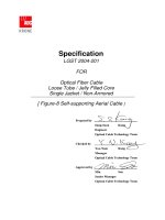
TECHNICAL SPECIFICATION
LOOSE TUBE DESIGN,
SINGLE JACKET/ SINGLE ARMOR, JELLY-FILLED,
F/O CABLE
KRSI-JF-510C-GSP
Page 2 of 8
1.
SCOPE
1.1
Application
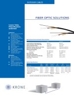
This specification covers the general requirements for fiber optic telecommunication
cables used for inter-building backbone in duct, direct buried and lashed aerial installation.
1.2
Cable Description
1)
Single Jacket/Single Armor Jelly filled Cable
Single and 50 or 62.5 Multi mode color coded fibers, jelly filled color coded loose
tubes, PE filler (if required), SZ-stranded around the dielectric central strength member,
jelly filled, dielectric strength member, water blocking tape, corrugated steel tape armor
and outer PE jacket
2.
OPTICAL FIBER
The optical, geometrical and mechanical performance of the optical fiber shall be in
accordance with Table 1 and 2 below.
Table 1. The Optical, Geometrical and Mechanical Performance of the
Multi Mode Fiber
ITEMS UNITS SPECIFICATION
50 Multi Mode 62.5 Multi Mode
Attenuation dB/km
3.5 at 850nm
1.0 at 1300nm
3.5 at 850nm
1.0 at 1300nm
Bandwidth MHz.km
400 at 850nm
600 at 1300nm
200 at 850nm
500 at 1300nm
Numerical Aperture - 0.20±0.015 0.275±0.015
Core Diameter
50±3.0 62.5±3.0
Core Non-circularity %
6.0
6.0
Cladding Diameter
125±2.0 125±2.0
Cladding Non-circularity %
2.0
2.0
Core/Cladding Concentricity Error
3.0
3.0
Coating Diameter
245±15 245±15
Proof Test Kpsi
100
100
*Note) Superior performance available upon request.
KRSI-JF-510C-GSP
Page 3 of 8
Table 2. The Optical, Geometrical and Mechanical Performance of the
Single Mode Fiber
ITEMS UNITS SPECIFICATION
Attenuation dB/km
0.4 at 1310nm
0.25 at 1550nm
Chromatic Dispersion ps/nm.km
3.2 at 1285nm ~ 1330nm
18 at 1550nm
Zero Dispersion Wavelength nm 1300 ~ 1324
Zero Dispersion Slope ps/nm
2
.km
0.093
Cut-off Wavelength
(λcc, 22m of a cabled fiber)
nm
1270
Mode Field Diameter
9.3± 1.0%
Mode Field Concentricity
0.8
Cladding Diameter
125±1.0
Cladding Non-circularity %
1.0
Coating Diameter
245±15
Proof Test kpsi
100
*Note) Superior performance available upon request.
3.
CABLE CONSTRUCTION
The construction of the cable shall be in accordance with Table 3 below.
Table 3. Construction of the Cable
ITEMS DESCRIPTION
Type of Fiber Single Mode or 62.5 Multi Mode or 50 Multi Mode
Number of Fibers 2 ~ 72
No. of Fibers per Tube Max. 12
Material PBT (Polybutylene Terephthalate)
Loose Buffer
Tube
Diameter Nom. 2.4mm
Filling Compound
in Loose Buffer Tube
Thixotropic Jelly Compound
Filling Compound
between Loose Buffer Tubes
Polybuthane Type Jelly Compound
Central Strength Member FRP(Fiberglass Reinforced Plastic)
Core Wrapping Tape
Plastic Tape
(To provide heat barrier and good forming of core)
KRSI-JF-510C-GSP
Page 4 of 8
Table 3. Construction of the Cable(continued)
ITEMS DESCRIPTION
Dielectric Strength Member
Glass yarns
(To provide the required tensile strength together
with the central strength member)
Water Blocking Material
Water Swellable Tape
(To prevent the ingress of water)
Material Steel Tape with Plastic Coating on Both Sides
Armor
Thickness
Nom. 0.15mm (Steel Tape)
Nom. 0.05mm (Plastic Coating)
Material Black HDPE
Outer Jacket
Thickness Nom. 1.8mm, Min. 1.25mm
4.
FIBER AND LOOSE BUFFER TUBE IDENTIFICATION
The color code of the loose buffer tubes and the individual fibers within each loose buffer
tube shall be in accordance with Table 4 below.
Table 4. The Color Code of the Individual Fibers and Loose Tubes
No. of Fibers/
Loose Buffer Tubes
Color No. of Fibers/
Loose Buffer Tubes
Color
1Blue7 Red
2 Orange 8 Black
3 Green 9 Yellow
4 Brown 10 Violet
5Gray11Pink
6 White 12 Aqua
KRSI-JF-510C-GSP
Page 5 of 8
5.
PHYSICAL / MECHANICAL / ENVIRONMENTAL PERFORMANCE
The mechanical and environmental performance of the cable shall be in accordance with
Table 5 below. Unless otherwise specified, all attenuation measurements required in this
section shall be performed at 1550nm for single mode fiber (SM) and at 1300nm for multi
mode fiber (MM).
Table 5. The Mechanical and Environmental Performance of the Cable
ITEMS
TEST METHOD AND
ACCEPTANCE CRITERIA
Tensile Loading
And Bending Test
# Test method: TIA/EIA-455-33A
-. Mandrel diameter: 30D (D = cable diameter)
-. Short term tensile load: 2,700N for 1 hour
-. Long term tensile load: 1,000N for 10 minutes
# Acceptance Criteria
-. Fiber strain: Less than 60% of the fiber proof strain
for short term tensile load
-. Attenuation increment:
0.10 dB (SM)
0.20 dB (MM)
for long term tensile load
Compressive Loading
Resistance Test
# Test method: TIA/EIA-455-41A
-. Applied load: 110 N/cm
-. Duration of loading: 10 minutes
# Acceptance Criteria
-. Attenuation Increment:
0.10 dB (SM)
0.20 dB (MM)
Repeated Impact Test
# Test method: TIA/EIA-455-25B
-. Height of impact: 150mm
-. Drop hammer mass: 2.0kg
-. No. of impact cycles: 20 cycles
# Acceptance Criteria
-. Attenuation Increment:
0.10 dB (SM)
0.20 dB (MM)
-. No jacket cracking and fiber breakage
Cyclic Flexing Test
# Test method: TIA/EIA-455-104A
-. Sheave diameter: 20D (D = cable diameter)
-. No. of flexing cycles: 25 cycles
-. Flexing speed: 30 cycles/minute
# Acceptance Criteria
-. Attenuation Increment:
0.10 dB (SM)
0.20 dB (MM)
-. No jacket cracking and fiber breakage