quyển sách hay nói về cầu bê tông
Bạn đang xem bản rút gọn của tài liệu. Xem và tải ngay bản đầy đủ của tài liệu tại đây (13.63 MB, 314 trang )
Design of Reinforced Concrete Bridges
CIV498H1 S Group Design Project
Instructor: Dr. Homayoun Abrishami
Team 2:
Fei Wei 1000673489
Jonny Yang 1000446715
Yibo Zhang 1000344433
Chiyun Zhong 999439022
Executive Summary
The entire project report consists of two parts. The first section, Part A, presents a
complete qualitative description of typical prestressed concrete bridge design process.
The second part, Part B, provides an actual quantitative detailed design a prestressed
concrete bridge with respect to three different design standards.
In particular, the first part of the report reviews the failure of four different bridges in the
past with additional emphasis on the De La Concorde Overpass in Laval, Quebec.
Various types of bridges in terms of materials used, cross-section shape and structural
type were investigated with their application as well as the advantages and disadvantages.
In addition, the predominant differences of the Canadian Highway and Bridge Design
Code CSA S6-14 and CSA S6-66, as well as AASHTO LRFD 2014 were discussed. After
that, the actual design process of a prestressed concrete bridge was demonstrated, which
started with identifying the required design input. Then, several feasible conceptual
design options may be proposed by design teams. Moreover, the purpose and
significance of structural analysis is discussed in depth, and five different typical analysis
software were introduced in this section. Upon the completion of structural analysis, the
procedure of detailed structure design and durability design were identified, which
included the choice of materials and dimensions of individual specimens as well as the
detailed design of any reinforcement profile. Last but not least, the potential construction
issues as well as the plant life management and aging management program were
discussed and presented at the end of the Part A.
On the other hand, the second part of this report presents a detailed structural design of
a prestressed concrete bridge with a span of 25 meters based on three different design
standards. It started off with a problem statement that defines the scope of the entire
design. The concept of influence line is used to analyze the moving track load, which is
then combined with other live loads and dead loads to come up with the entire shear force
and bending moment envelope along the bridge. Once all the design loads had been
determined, detailed computational designs were performed for both prestressed
concrete girders and reinforced concrete decks with respect to three different bridge
design standards. Aside from the structural designs, the durability concrete mix design is
also provided as part of the bridge design, which takes the environmental conditions into
consideration. Finally, the detailed drawings of the bridge are attached at the end of the
entire report.
This design report summarized the knowledge and skills that our design team has gained
from this course of Capstone Design Project as well as the rest of undergraduate program
curriculum. It also provides strong insight on the connections and differences between
different design standards, and the impacts these differences could make to the designs.
Furthermore, the past failures included in this report has taught us that not only theoretical
knowledge, but also the responsibilities of being a future structural engineer. The outlined
step-by-step design procedure in this design report may be used for future reference on
similar design projects.
Table of Content
Company Overview
Team
Part A Design Handbook
Chapter 1: Introduction
Chapter 2: Past Experiences from Construction Failures and Learning Lessons
Chapter 3: Types of Bridges
Chapter 4: Design Criteria
Chapter 5: Design Input
Chapter 6: Conceptual Design
Chapter 7: Structural Analysis
Chapter 8: Detailed Design
Chapter 9: Durability Design
Chapter 10: Construction Issues
Chapter 11: Plant Life Management (PliM)
Part B Detailed Calculation
Chapter 1: Introduction
Chapter 2: Project Statement
Chapter 3: Structural Analysis – Influence Line
Chapter 4: Design Loads
Chapter 5: Design of Prestressed Concrete Girder
Chapter 6: Design of Reinforced Concrete Deck
Chapter 7: Durability Design
ii
Overview
We specialized in bridge designs with different types and simplify the design and enhance
the safety of structures. We take pride in collaborating in the creation of safer structures
through elegant designs. BridD&E Design and Engineering Consulting Corporation is an
innovator in Bridge Engineering.
iii
Team
Chiyun Myron Zhong
Myron will receive his Bachelor of Applied Science in
Civil Engineering from the University of Toronto in 2017,
and will start his PhD studies in structural engineering
at the University of Toronto. Myron is the recipient of the
University
of
Toronto
Excellence
Award,
the
Engineering 8T4 Leadership Award, and the Marcia
Lamont Scott CIV4T7 Scholarship. In addition to his
expertise in non-linear finite element analysis, seismic
design, and low-cycle fatigue design, Myron also has
extensive experience in concrete structure design and
detailing.
Yibo Zhang
Yibo is currently a 4th year civil engineering student
at the University of Toronto. After graduation, he will
start the Master of Mathematical Finance at the
University of Toronto. Yibo has various interests from
cutting-edge technology to financial market. He
worked as a research assistant at City University of
Hong Kong focusing on the application of Artificial
Neural Network on rock blasting. Also, he has
particular interest on the advanced applications of
solid mechanics such as Aerospace structures and
nano-scale mechanics.
iv
Fei Wei
As a fourth-year student at the University of Toronto,
Fei is studying civil engineering with an emphasis in
structural engineering. During the undergraduate
studies, Fei received the University of Toronto
Excellence Award in 2016 while working in the
Structural Testing Facility at the University of Toronto
as a Research Assistant. This invaluable experience
allowed him to become involved with three significant
projects at the leading edge of current design
technology for steel structures.
Johnny Yang
Johnny is currently a fourth-year student studying civil
engineering in University of Toronto. “I cannot wait to
graduate let me tell you this.” ------Johnny
v
Part A: Design Handbook
Table of Contents
Executive Summary ................................................................................................................ i
Overview.............................................................................................................................. iii
Team .................................................................................................................................... iv
Chapter 1 Introduction ....................................................................................................... 1-1
Chapter 2. Past Experiences from Construction Failures and Learning Lessons ..................... 2-1
2.1 Introduction ..........................................................................................................................2-2
2.2 de la Concorde Overpass Collapse ..........................................................................................2-2
2.2.1 History of the Bridge ................................................................................................................ 2-2
2.2.2 Bridge Type and Structure Detail ............................................................................................. 2-2
2.2.3 Failure of the Overpass ............................................................................................................ 2-4
2.2.4 Reasons for Failure ................................................................................................................... 2-5
2.2.5 Lessons Learned ....................................................................................................................... 2-8
2.3 Seongsu Bridge (Seoul, South Korea) ......................................................................................2-9
2.3.1 History ...................................................................................................................................... 2-9
2.3.2 Structure Type ........................................................................................................................ 2-10
2.3.3 Failure Description ................................................................................................................. 2-10
2.3.4 Reasons for Failure ................................................................................................................. 2-11
2.3.5 Lesson Learned ....................................................................................................................... 2-12
2.4 Bridge 9340 Collapse ........................................................................................................... 2-13
2.4.1 History .................................................................................................................................... 2-13
2.4.2 Bridge Type and Structure Detail ........................................................................................... 2-14
2.4.3 Failure ..................................................................................................................................... 2-15
2.4.4 Causes of the Failure .............................................................................................................. 2-16
2.4.5 Lesson Learned ....................................................................................................................... 2-18
2.5 Tacoma Narrows Bridge Collapse ......................................................................................... 2-18
2.5.1 Background Information ........................................................................................................ 2-19
2.5.2 Failure ..................................................................................................................................... 2-20
2.5.3 Lesson Learned ....................................................................................................................... 2-23
2.6 Conclusion .......................................................................................................................... 2-23
References................................................................................................................................ 2-24
Chapter 3. Types of Bridges ................................................................................................ 3-1
3.1 Introduction ..........................................................................................................................3-3
3.2 Material ................................................................................................................................3-3
3.2.1 Masonry ................................................................................................................................... 3-3
3.2.2 Timber ...................................................................................................................................... 3-6
3.2.3 Steel .......................................................................................................................................... 3-7
3.2.4 Concrete ................................................................................................................................. 3-11
3.3 Cross Sections in Reinforced and Prestressed Concrete Bridge .............................................. 3-20
3.4 Bridge Types........................................................................................................................ 3-21
3.4.1 Beam Bridge ........................................................................................................................... 3-22
3.4.2 Truss Bridge ............................................................................................................................ 3-26
3.4.3 Arch Bridge ............................................................................................................................. 3-31
3.4.4 Cantilever Bridge .................................................................................................................... 3-35
3.4.5 Suspension Bridge .................................................................................................................. 3-42
3.4.6 Cable Stayed Bridge................................................................................................................ 3-47
3.5 Construction Technology ..................................................................................................... 3-52
3.5.1 Concrete Cast - Cast in Situ and Precast ................................................................................ 3-53
3.5.2 Concrete Installation .............................................................................................................. 3-54
3.6 Conclusion .......................................................................................................................... 3-58
References................................................................................................................................ 3-59
Chapter 4 Design Criteria .................................................................................................... 4-1
4.1 Introduction ..........................................................................................................................4-4
4.1.1 Bridge Behaviour ...................................................................................................................... 4-4
4.1.2 Bridge Loading .......................................................................................................................... 4-7
4.2 CSA S6-14 Design Specification [6] .........................................................................................4-8
4.2.1 Terminology ............................................................................................................................. 4-9
vii
4.2.2 General ..................................................................................................................................... 4-9
4.2.3 Design Philosophy .................................................................................................................. 4-10
4.2.4 Material .................................................................................................................................. 4-10
4.2.5 Limit States Design ................................................................................................................. 4-19
4.2.6 Load Factors ........................................................................................................................... 4-21
4.2.7 Dead Loads ............................................................................................................................. 4-21
4.2.8 Live Loads ............................................................................................................................... 4-23
4.2.9 Wind Loads ............................................................................................................................. 4-25
4.2.10 Earthquake ........................................................................................................................... 4-25
4.2.11 Reinforced Concrete Design ................................................................................................. 4-25
4.2.12 Prestressed Concrete Design ............................................................................................... 4-28
4.2.13 Durability Design .................................................................................................................. 4-28
4.3 CSA S6-14 versus AASHTO 2014 Design Specifications [16] .................................................... 4-33
4.3.1 General ................................................................................................................................... 4-33
4.3.2 Limit States Design ................................................................................................................. 4-33
4.3.3 Load Factor ............................................................................................................................. 4-35
4.3.4 Dead Loads ............................................................................................................................. 4-36
4.3.6 Wind Loads ............................................................................................................................. 4-37
4.3.7 Earthquake ............................................................................................................................. 4-38
4.4 CSA S6-14 versus CSA S6-66 Design Specifications [17].......................................................... 4-38
4.4.1 General Information ............................................................................................................... 4-38
4.4.2 Design Philosophy .................................................................................................................. 4-38
4.4.3 Loads and Forces .................................................................................................................... 4-39
4.4.4 Design Truck Load and Lane Load .......................................................................................... 4-40
4.4.5 Reinforced Concrete Design ................................................................................................... 4-42
4.4.6 Prestressed Concrete Design.................................................................................................. 4-43
4.5 Design Steps........................................................................................................................ 4-44
4.6 Conclusion .......................................................................................................................... 4-46
References................................................................................................................................ 4-47
Chapter 5 Design Input ....................................................................................................... 5-1
5.1 Introduction ..........................................................................................................................5-2
viii
5.2 Client Requirement ...............................................................................................................5-2
5.2.1 Scope of the Design .................................................................................................................. 5-2
5.2.2 Budget ...................................................................................................................................... 5-2
5.2.3 Schedule ................................................................................................................................... 5-3
5.2.4 Service Life ............................................................................................................................... 5-3
5.2.5 Additional Requirements ......................................................................................................... 5-3
5.3 Site Condition........................................................................................................................5-4
5.3.1 Site Location ............................................................................................................................. 5-4
5.3.2 Site Impacts .............................................................................................................................. 5-6
5.4 Government Regulation.........................................................................................................5-7
5.4.1 Required Design Codes............................................................................................................. 5-7
5.4.2 Applicable Additional Requirements and Regulations ............................................................. 5-8
5.5 Constructability .....................................................................................................................5-9
5.5.1 Construction knowledge .......................................................................................................... 5-9
5.5.2 Construction Techniques........................................................................................................ 5-10
5.5.3 Design Consideration ............................................................................................................. 5-10
5.5.4 Project Management and Communication ............................................................................ 5-10
5.6 Conclusion .......................................................................................................................... 5-11
Reference ................................................................................................................................. 5-12
Chapter 6 Conceptual Design .............................................................................................. 6-1
6.1 Introduction ..........................................................................................................................6-2
6.2 Background Information of De la Concorde Overpass .............................................................6-2
6.3 Design Objective: ..................................................................................................................6-4
6.3.1 Aesthetics and Uniformity with existing overpass ................................................................... 6-4
6.2.2 Bridge Performances ................................................................................................................ 6-5
6.2.3 Bridge Construction.................................................................................................................. 6-5
6.2.4 Environmental Considerations ................................................................................................. 6-6
6.3 Proposed Conceptual Designs ................................................................................................6-6
6.3.1 Multicell Box Girder.................................................................................................................. 6-6
6.3.2 Slab on Precast Pretensioned I Girder...................................................................................... 6-8
6.3.3 Asymmetrical Cable Stayed Bridge......................................................................................... 6-10
ix
6.4 Evaluation of Conceptual Designs ........................................................................................ 6-11
6.5 Conclusion .......................................................................................................................... 6-13
Reference ................................................................................................................................. 6-14
Chapter 7 Structural Analysis .............................................................................................. 7-1
7.1 Introduction ..........................................................................................................................7-3
7.2 Structural Analysis Overview .................................................................................................7-3
7.2.1 The Purpose of Structural Analysis........................................................................................... 7-3
7.2.2 Required Inputs ........................................................................................................................ 7-4
7.2.3 Structural Indeterminacy ......................................................................................................... 7-6
7.2.4 Equilibrium, compatibility, and constitutive equations ........................................................... 7-7
7.2.5 Linear vs. Nonlinear Analysis .................................................................................................... 7-8
7.2.6 Finite Element Analysis (FEA) ................................................................................................... 7-9
7.2.7 The Importance of Hand Calculations .................................................................................... 7-10
7.3 Modelling Methodology ...................................................................................................... 7-10
7.3.1 Pre-Processing ........................................................................................................................ 7-11
7.3.2 Processing............................................................................................................................... 7-11
7.3.3 Post-Processing ...................................................................................................................... 7-11
7.4 Structural Analysis Computer Packages ................................................................................ 7-12
7.4.1 SAP2000 ................................................................................................................................. 7-12
7.4.2 RISA 3D ................................................................................................................................... 7-16
7.4.3 MIDAS Civil ............................................................................................................................. 7-18
7.4.4 ANSYS ..................................................................................................................................... 7-21
7.4.5 Abaqus FEA ............................................................................................................................. 7-23
7.5 Conclusion .......................................................................................................................... 7-27
References................................................................................................................................ 7-28
Chapter 8 Detailed Design .................................................................................................. 8-1
8.1 Introduction ..........................................................................................................................8-3
8.2 Bridge Elements ....................................................................................................................8-3
8.3 Material ................................................................................................................................8-4
8.3.1 Concrete ................................................................................................................................... 8-4
x
8.3.2 Reinforcement.......................................................................................................................... 8-5
8.4 Design of Prestressed Concrete I Girder .................................................................................8-9
8.4.1 Determine the Applied Loads................................................................................................... 8-9
8.4.2 Select Cross Section Dimension ............................................................................................. 8-10
8.4.3 Determine Tendon Profile ...................................................................................................... 8-11
8.4.4 Design for Flexure .................................................................................................................. 8-12
8.4.5 Design for Shear ..................................................................................................................... 8-18
8.5 Design of Reinforced Concrete Bridge Deck .......................................................................... 8-22
8.5.1 Flexure Design ........................................................................................................................ 8-22
8.5.2 Crack Control .......................................................................................................................... 8-24
8.5.3 Design for Shear ..................................................................................................................... 8-25
8.5.4 Deflections.............................................................................................................................. 8-26
8.5.5 Design using AASHTO LRFD-14 ............................................................................................... 8-27
8.5.6 Design using CSA S6-66 .......................................................................................................... 8-30
8.6 Conclusion .......................................................................................................................... 8-31
References................................................................................................................................ 8-32
Chapter 9 Durability Design ................................................................................................ 9-1
9.0 Introduction ..........................................................................................................................9-3
9.1 Material Durability ................................................................................................................9-3
9.1.1 Concrete ................................................................................................................................... 9-3
9.1.2 Reinforce steel.......................................................................................................................... 9-9
9.2 External Effects .....................................................................................................................9-9
9.2.1 Physical Effects ......................................................................................................................... 9-9
9.2.2 Chemical Effects ..................................................................................................................... 9-11
9.3 Design for Durability in S6-14............................................................................................... 9-16
9.3.1 Introduction............................................................................................................................ 9-16
9.3.2 Definitions of Terms ............................................................................................................... 9-16
9.3.3 Design for Durability............................................................................................................... 9-16
9.3.4 Protective Measures .............................................................................................................. 9-19
9.4 Design for Durability in CSA A23.1........................................................................................ 9-25
9.5 Case Study of Confederation Bridge ..................................................................................... 9-28
xi
9.5.1 Durability Design .................................................................................................................... 9-29
9.6 Conclusion .......................................................................................................................... 9-32
Reference: ................................................................................................................................ 9-33
Chapter 10 Construction Issues ......................................................................................... 10-1
10.1 Introduction ...................................................................................................................... 10-2
10.2 Construction Safety ........................................................................................................... 10-2
10.2.1 Occupational Health and Safety Act, R.S.O. 1990, c. O.1 [2]................................................ 10-2
10.2.2 Workplace Hazardous Materials Information System 2015 ................................................ 10-3
10.2.3 Construction Safety Signals .................................................................................................. 10-4
10.2.4 Personal Protective Equipment............................................................................................ 10-7
10.3 Site and Schedule .................................................................................................................... 10-8
10.3.1 Preparation of the Construction Site ................................................................................... 10-8
10.4 Quality Control .................................................................................................................. 10-9
10.4.1 Method of Quality Control ................................................................................................. 10-10
10.4.2 Quality Control of Materials ............................................................................................... 10-10
10.4.3 Quality of Geometry ........................................................................................................... 10-14
10.5 Budget ............................................................................................................................ 10-15
10.6 Conclusion....................................................................................................................... 10-15
10.7 References: ..................................................................................................................... 10-16
Chapter 11 Plant Life Management (PLiM) ........................................................................ 11-1
11.0 Introduction ...................................................................................................................... 11-2
11.1 Plant Life Management (PLiM) ........................................................................................... 11-2
11.2 Design Requirements [2].................................................................................................... 11-3
11.2.1 Structural Design variables [2] ............................................................................................. 11-4
11.2.2 Durability Design variables [2] ............................................................................................. 11-6
11.2.3 Construction Phase Variables............................................................................................... 11-7
11.3 Ageing Management Program (AMP) [2] ............................................................................ 11-9
11.3.1 Deterioration Mechanism .................................................................................................. 11-11
11.3.2 Evaluation Methodology [2]............................................................................................... 11-12
11.3.3 Repair and Replacement [2] ............................................................................................... 11-13
xii
11.3.4 Decommissioning [2] .......................................................................................................... 11-13
11.4 Conclusion....................................................................................................................... 11-14
11.5 References ...................................................................................................................... 11-15
xiii
Chapter 1 Introduction
Part A of the design report emphasizes on introducing the typical process of designing
either reinforced or prestressed concrete bridges, as well as the additional consideration
that a design team need to take through each phases of the design process. A wide range
of contents with respect to bridge design process are covered in this part of the design
report.
Eleven chapters are included in Part A with each chapter serving a unique purpose. Firstly,
four case studies of bridge collapse were studied, including the collapse of De La
Concorde Overpass, Sengsu Bridge, I 35-W Mississippi River Bridge and Tacoma
Narrows Bridge. Lessons learned from these failures were also discussed to prevent any
future disasters. In Chapter 3, different types of bridges used in construction practices
were investigated. These bridges vary in terms of materials used (wood, concrete, steel
etc.) and structural type (cantilever, truss, suspension etc.). The application, including
advantages and disadvantages, of each type of bridges were also discussed in this
chapter. Connections and differences between the relevant clauses of the Canadian
Highway Bridge Design Code S6-14, AASHTO LRFD 2014 Bridge Design Specification,
and Design of Highway Bridges S6-66 were explored in Chapter 4.
Once the background information about bridge design was discussed in the first few
chapters. Chapter 5 determined all the necessary design inputs, such as any client
requirements, site conditions and government regulations. With the design inputs
determined, several conceptual designs need to be proposed. In Chapter 6, these
proposed designs for the De La Concorde Overpass replacement were described and
evaluated based on the defined design objectives, and the most appropriate design was
determined at the end of the chapter based on evaluation matrix. The research regarding
to the methods, tools and software of structural analysis were conducted in Chapter 7.
Five different structural design software, including SAP 2000, RISA 3D, Midas Civil,
Ansys and Abaqus FEA, were explored with their applications and limitations identified.
1-1
Upon the completion of structural analysis, the bridge will be designed in detail. The step
by step procedure of determining the concrete section dimensions, prestressing tendon
profile, reinforcing bar layout and material properties are specified in Chapter 8.
Aside from structural designs, the durability design is also crucial for a bridge. Chapter 9
outlined the steps that need to be followed to ensure that the bridge could resist the
severe external environment within its service life. Moreover, related construction issues
such as construction safety, scheduling, on site quality control and budget issues were
investigated in Chapter 10. In order to maintain the strength, serviceability and durability
requirements during the entire service life, plant life management (PLiM) and aging
management program (AMP) were discussed in Chapter 11.
Overall, the Part A of the design report presents an overview of the design process of
typical reinforced or prestressed concrete bridges. It also outlines additional
considerations that needs to be taken for a design to be successful.
1-2
Chapter 2. Past Experiences from Construction Failures and
Learning Lessons
Table of Contents
Chapter 2. Past Experiences from Construction Failures and Learning Lessons ..........................
2.1 Introduction ..........................................................................................................................2-1
2.2 de la Concorde Overpass Collapse ..........................................................................................2-1
2.2.1 History of the Bridge ................................................................................................................ 2-1
2.2.2 Bridge Type and Structure Detail ............................................................................................. 2-1
2.2.3 Failure of the Overpass ............................................................................................................ 2-3
2.2.4 Reasons for Failure ................................................................................................................... 2-4
2.2.5 Lessons Learned ....................................................................................................................... 2-7
2.3 Seongsu Bridge (Seoul, South Korea) ......................................................................................2-8
2.3.1 History ...................................................................................................................................... 2-8
2.3.2 Structure Type .......................................................................................................................... 2-9
2.3.3 Failure Description ................................................................................................................... 2-9
2.3.4 Reasons for Failure ................................................................................................................. 2-10
2.3.5 Lesson Learned ....................................................................................................................... 2-11
2.4 Bridge 9340 Collapse ........................................................................................................... 2-12
2.4.1 History .................................................................................................................................... 2-12
2.4.2 Bridge Type and Structure Detail ........................................................................................... 2-13
2.4.3 Failure ..................................................................................................................................... 2-14
2.4.4 Causes of the Failure .............................................................................................................. 2-15
2.4.5 Lesson Learned ....................................................................................................................... 2-17
2.5 Tacoma Narrows Bridge Collapse ......................................................................................... 2-17
2.5.1 Background Information ........................................................................................................ 2-18
2.5.2 Failure ..................................................................................................................................... 2-19
2.5.3 Lesson Learned ....................................................................................................................... 2-22
2.6 Conclusion .......................................................................................................................... 2-22
References................................................................................................................................ 2-23
2-1
2.1 Introduction
Studying and reviewing the failures of the past is beneficial in preventing future
incidences of its kind. This chapter presents following four case studies of past bridge
failures in order to understand the risk of failure of bridges and acquire knowledge on
the failure mechanisms of existing bridge structures. Studies aim independently for
different types of concrete bridge failures. Most failures occur due to a combination of
various reasons, ranging from human errors by limited knowledge in planning, design,
construction, inspection and maintenance, as well as uncontrollable factors such as
accidents and natural hazards. In general, failures of bridge could result in huge direct
and indirect economic losses, and even losses of lives. Bridges, and any other forms of
structures, need to be designed to exceed the latest codes and standards, constructed
strictly by specifications, as well as inspected and maintained until the end of their
service life, in order to minimize the likelihood of any future collapse.
2.2 de la Concorde Overpass Collapse
To clearly understand the failure mechanism of the De La Concorde Overpass, it is first
necessary to provide the fundamental characteristics of its design. Assessments of
possible causes conducted by the Commission is summarized. Last but not the least, this
case study is concluded by lessons learned from the collapse of the overpass.
2.2.1 History of the Bridge
The De La Concorde Overpass was designed and constructed in 1970s by the
engineering firm Desjardins Sauriol & Associes (DSA) in accordance with CSA S6-1966.
The overpass was considered to be innovative in North America at the time when it was
designed and built [1].
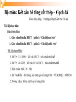
2.2.2 Bridge Type and Structure Detail
De la Concorde Overpass uses prestressed concrete box girders (Figure 2.1) to enable
a single 90ft central span without any intermediate supports, as shown in Figure 2.2. This
2-2
feature enables the unobstructed crossing of two heavy traffic arteries in Laval. To
support the two ends of the overpass, the box girders were placed side by side on the
abutment forming by thick cantilever reinforced concrete slabs of 4.24ft (Figure 2.3). As
can be seen from Figure 2.4, the overpass carries a total of six lanes of traffic, with three
westbound and three eastbound [1].
Figure 2.1 Elevation view of the de la Concorde overpass showing central span and
abutments [1]
Figure 2.2 Cross-section of the de la Concorde overpass [1]
2-3
Figure 2.3 Detail of the eastern abutment [1]
Figure 2.4 Plan view of the de la Concorde overpass [1]
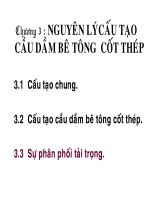
2.2.3 Failure of the Overpass
On September 30, 2006, the road and overpass was inspected by a road supervisor and
a crack (Figure 2.5) was noticed. Immediate inspection by an engineer was requested.
However, the overpass did not last to the inspection. Approximately thirty minutes later,
the unreinforced part of the concrete overpass split along an inclined surface down to the
2-4
bottom layer of the reinforcement in the slab. The structure collapsed suddenly in a single
block due to a shear failure in the east abutment cantilever and hit the autoroute below
[1]. The collapsed overpass crushed two vehicles under it, killing five people and seriously
injured six passengers who went over the edge while travelling on the overpass [2].
Figure 2.5 The de la Concorde overpass after the east span failure [1]
2.2.4 Reasons for Failure
The collapse of the de la Concorde overpass is the result of a series of physical causes
that gradually deteriorated the structure over years, eventually causing a shear failure in
the southeast cantilever [1]. This was caused by a horizontal plane fracture that had
accumulated for many years - an indication of severe state of structure deterioration. As
can be seen from Figure 2.5, the complete east span collapsed onto AutoRoute 19 below
due to its self-weight.
According to the investigation by the commission, three main causes of the failure were
determined and agreed by all the experts [1] [3]:
1. The steel reinforcement in the concrete slab was improperly designed, resulting in
a concretion of reinforcement in the upper portion of the abutment. This created a
2-5
weak plane that was susceptible to horizontal cracking. However, the improper
design was caused by the limit of general knowledge since this design did not
contravene the code provisions of the time.
2. The reinforcement was not installed into the specified location during the
construction, as defined in the design. The incorrectly placed #6 diagonal bars
generated a zone of weakness which exacerbated the design weakness. As shown
in Figure 2.7, there was a misalignment between the design layout and the “as
built” layout. This cause was due to the unprofessional work by the contractors and
inspecting engineers.
3. The concrete quality used in the abutments was too low for its purpose thus not
able to withstand the deterioration by freeze-thaw cycles and the corrosion by deicing salts. The poor quality of concrete was a result of the lack of communication
at all levels, including the confusion in the specification of concrete in design.
In addition to the above three causes, the commission also identified three other
contributing factors which were not universally agreed by every party [1]:
1. The absence of shear reinforcement in the thick slab causes insufficient control on
the internal cracking. It was believed that the design of the thick slab on the
overpass would have required shear reinforcement if design had based on current
codes, such design would have prevented the sudden collapse of the overpass.
2. Poor waterproofing on the surface of the thick slab saturates water into the
concrete, thus exacerbated the freeze-thaw deterioration. The waterproofing
membrane was supposed to be installed for the 1992 repair work, whereas it was
determined that it was not the case. The absence of adequate protection on the
thick slab was a major factor of the failure.
3. The 1992 repair work removes excessive amount of concrete than it should have
done. Consequently, more reinforcing rebars were exposed which contributed to
accelerate propagation of the concrete crack. Deficiencies in the overpass were
observed but not addressed during the repair work.
2-6
Figure 2.6 Perspective View of the Rebar Layout in the Chair Bearing Support Region
as Specified on the as Designed Drawings
Figure 2.7 Details of the reinforcement layouts as-designed versus as-built
in the east abutment
2-7
2.2.5 Lessons Learned
As the result of the commission investigation on the collapse of the de la Concorde
overpass, recommendations were made in terms of code provision, management,
inspection and maintenance requirements for all bridge structures. The commission
identified four organizations and individuals responsible for unprofessional work as
contributing factors to the overpass failure [1]. To ensure such events never recur, the
commission made recommendations based on a variety of sources [1]:
● Revise CSA-S6-2006 to require minimum shear reinforcement in thick slabs
● Update CSA-S6-2006 and CSA-A23.1-2004 to require the use of high-quality
concrete for all bridges
● Provide an effective surveillance of scientific intelligence processes to ensure
designers updated with new developments in the field.
● Update the inspection and evaluation manuals to emphasis on the timing of
interventions, crack inspections and interpretation and structural condition
assessment.
● Implement a control and supervision system with regard to bridge design and
construction.
● Develop a national bridge rehabilitation program to inspect and rehabilitate existing
bridges nationwide.
Other Lessons Learned:
● The need of extensive research to understand the behavior of concrete structure
under a variety of loading scenario.
● Increase in government budget for critical infrastructures to prevent the use of low
quality material during construction and provide sufficient funding for maintenance
and inspection.
2-8
2.3 Seongsu Bridge (Seoul, South Korea)
In order to have a clear understand of the failure mechanism of the Seongsu Bridge, it is
first necessary to provide the fundamental characteristics of its design. Assessments of
possible causes conducted by the Commission is summarized. Last but not the least, this
case study is concluded by lessons learned from the collapse of the bridge.
2.3.1 History
The Seongsu Bridge is a bridge over the Han River in Seoul linking the Seongdong and
Gangnam districts. However, the original Seongsu Bridge collapsed on October 21, 1994
when it was still in service. A bus and 6 passenger cars fell into Han River due to the
collapse. Since it was the morning peak hour, this accident caused 32 people died and
17 people injured [5].
Figure 2.8 Seongsu Bridge after collapse [6].
2-9