Power Electronic Handbook P10
Bạn đang xem bản rút gọn của tài liệu. Xem và tải ngay bản đầy đủ của tài liệu tại đây (204.31 KB, 16 trang )
10
AC Machines
Controlled as
DC Machines
(Brushless DC
Machines/Electronics)
Hamid A. Toliyat
Texas A&M University
Tilak Gopalarathnam
Texas A&M University
10.1
10.2
Introduction
Machine Construction
Permanent Magnets • Stator Windings
10.3
Motor Characteristics
Mathematical Model
10.4
Power Electronic Converter
Unipolar Excitation • Fault-Tolerant
Configuration • Current Source Inverter
10.5
Position Sensing
10.6
10.7
10.8
Pulsating Torque Components
Torque-Speed Characteristics
Applications
Position Sensorless Control
10.1 Introduction
Brushless DC (BLDC) motors are synchronous motors with permanent magnets on the rotor and
armature windings on the stator. Hence, from a construction point of view, they are the inside-out version
of DC motors, which have permanent magnets or field windings on the stator and armature windings
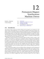
on the rotor. A typical BLDC motor with 12 stator slots and four poles on the rotor is shown in Fig. 10.1.
The most obvious advantage of the brushless configuration is the removal of the brushes, which
eliminates brush maintenance and the sparking associated with them. Having the armature windings on
the stator helps the conduction of heat from the windings. Because there are no windings on the rotor,
electrical losses in the rotor are minimal. The BLDC motor compares favorably with induction motors
in the fractional horsepower range. The former will have better efficiency and better power factor and,
therefore, a greater output power for the same frame, because the field excitation is contributed by the
permanent magnets and does not have to be supplied by the armature current.
These advantages of the BLDC motor come at the expense of increased complexity in the electronic
controller and the need for shaft position sensing. Permanent magnet (PM) excitation is more viable in
smaller motors, usually below 20 kW. In larger motors, the cost and weight of the magnets become
© 2002 by CRC Press LLC
FIGURE 10.1 Three-phase BLDC motor with four poles on the rotor and 12 stator slots.
excessive, and it would make more sense to opt for excitation by electromagnetic or induction means.
However, with the development of high-field PM materials, PM motors with ratings of a few megawatts
have been built.
10.2 Machine Construction
BLDC motors are predominantly surface-magnet machines with wide magnet pole-arcs and concentrated
stator windings. The design is based on a square waveform distribution of the air-gap flux density
waveform as well as the winding density of the stator phases in order to match the operational characteristics of the self-controlled inverter [1].
Permanent Magnets
BLDC motors obtain life-long field excitation from permanent magnets mounted on the rotor surface.
Advances in permanent magnet manufacturing and technology are primarily responsible for lowering
the cost and increasing the applications of BLDC motors. Ferrite or ceramic magnets are the most popular
choices for low-cost motors. These magnets are now available with a remanence of 0.38 T and an almost
straight demagnetization characteristic throughout the second quadrant. For special applications, magnetic materials with high-energy products such as neodymium-iron-boron (Nd-Fe-B) are used. The high
remanence and coercivity permit marked reductions in motor frame size for the same output compared
with motors using ferrite magnets. However, the size reduction is at the expense of increased cost of the
magnets.
The primary considerations while choosing the magnetic material for a motor are the torque per unit
volume of the motor, the operating temperature range, and the severity of the operational duty of the
magnet [2]. For maximum power density, the product of the electric and magnetic loadings of the motor
© 2002 by CRC Press LLC
must be as high as possible. A high electric loading necessitates a long magnet length in the direction of
magnetization and a high coercivity. A high power density also requires the largest possible magnet
volume. Exposure to high temperatures tends to deteriorate the remanent flux density and coercive force
of permanent magnets. Hence, the highest operating temperature must be considered while choosing
the magnets. Magnets can also be demagnetized by fault currents such as short-circuit currents produced
by inverter faults. Hence, protective measures are usually taken in the inverter and control electronics to
limit the magnitude of the armature currents to a safe value.
The magnets are constructed in the form of arcs, radially magnetized, and glued onto the surface of
the rotor with adjacent rotor poles of opposite magnetic polarity as shown in Fig. 10.1. The number of
rotor poles is inversely proportional to the maximum speed of rotation, and is frequently chosen to meet
manufacturing constraints. Most BLDC motors have four, six, or eight poles, with four the most popular
choice.
Stator Windings
BLDC motors are often assumed to have three phases, but this is not always the case. Small motors for
applications such as light-duty cooling fans have minimal performance requirements, and it is costeffective to build them with just one or two phases. On the other hand, it is preferable to use a high
phase number for large drives with megawatt ratings. This reduces the power-handling capacity of a
single phase, and also incorporates some degree of fault tolerance. Machines with as many as 15 phases
have been built for ship propulsion. Although these are special-purpose designs, motors with four and
five phases are quite common.
The number of stator slots is chosen depending on the rotor poles, phase number, and the winding
configuration. In general, a fractional slots/pole design is preferred to minimize cogging torque [3]. The
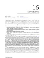
motor of Fig. 10.2 has six slots, which is not a multiple of the number of poles, and is hence a fractional
slots/pole design. The windings could be lap-wound or concentric-wound, and the coil span could be
full-pitch or short-pitch, depending on the crest width of the back-emf desired. There are virtually infinite
A+
C−
A−
C+
B+
B−
B−
B+
C+
A−
C−
A+
FIGURE 10.2 Three-phase BLDC motor with six slots and four poles.
© 2002 by CRC Press LLC
combinations of the above design factors, and it is up to the ingenuity of the designer to select one that
is best suited to the inverter characteristics and meets design specifications.
10.3 Motor Characteristics
The air-gap flux-density waveform is essentially a square wave, but fringing causes the corners to be
somewhat rounded. As the rotor rotates, the waveform of the voltage induced in each phase with respect
to time is an exact replica of the air-gap flux-density waveform with respect to rotor position. Because
of fringing, the back-emf waveform takes on a trapezoidal shape. The shape of the back-emf waveform
distinguishes the BLDC motor from the permanent magnet synchronous motor (PMSM), which has a
sinusoidal back-emf waveform. This has given rise to the terminology “trapezoidal motor” and “sinusoidal
motor” for describing these two permanent magnet AC (PMAC) machines.
The back-emf voltages induced in each phase are similar in shape and are displaced by 120° electrical
with respect to each other in a three-phase machine. By injecting rectangular current pulses in each phase
that coincides with the crest of the back-emf waveform in that phase, it is possible to obtain an almost
constant torque from the BLDC motor. The crest of each back-emf half-cycle waveform should be as
broad as possible (≥120° electrical) to obtain smooth output torque. This condition is satisfied by the
12-slot motor of Fig. 10.1 because it has full-pitched coils, but not by the six-slot motor of Fig. 10.2
because the coil spans are shorter than the pole arcs. The two back-emf waveforms calculated using the
finite-element method are plotted in Fig. 10.3 and it can be seen that the six-slot motor has a smaller
crest width, and is hence not suitable for 120° bipolar excitation. However, it can be used with other
excitation waveforms as discussed in the section on unipolar excitation.
50
40
12 slots
6 slots
30
20
Back-emf (V)
10
0
-10
-20
-30
-40
-50
0
20
40
60
80
100
Rotor position (deg)
FIGURE 10.3 Back-emf waveforms of the 12-slot and the 6-slot motors.
© 2002 by CRC Press LLC
120
140
160
180
E
I
Phase A
180
360
Phase B
Phase C
Te
Torque
S5
S6
S1
S6
S1
S2
S3
S2
S3
S4
S5
S4
S5
S6
Active
switches
FIGURE 10.4 Back-emf and phase current waveforms for three-phase BLDC motor with 120° bipolar currents.
+
D3
D1
S1
D5
S5
S3
ph A
Vdc
ph B
BLDC
Motor
ph C
S2
S6
S4
D4
D6
D2
FIGURE 10.5 Schematic of IGBT-based inverter for three-phase BLDC motor.
The ideal back-emf voltage and 120° phase current waveforms for a three-phase BLDC motor are
shown in Fig. 10.4. The inverter switches that are active during each 60° interval are also shown corresponding to the inverter circuit of Fig. 10.5. The simplicity of this scheme arises from the fact that during
any conduction interval, there is only one current flowing through two phases of the machine, which
can be sensed using a single current sensor in the DC link. Because there are only two inverter switches
active at any time, this is also called the two-switch conduction scheme, as opposed to the three-switch
conduction scheme used in PMSM motor drives.
The amplitude of the phase back-emf is proportional to the rotor speed, and is given by
E = kfw m
© 2002 by CRC Press LLC
(10.1)
where k is a constant that depends on the number of turns in each phase, φ is the permanent magnet
flux, and ωm is the mechanical speed.
During any 120° interval, the instantaneous power being converted from electrical to mechanical is
the sum of the contributions from two phases in series, and is given by
P o = w m T e = 2EI
(10.2)
where Te is the output torque and I is the amplitude of the phase current. From Eqs. (10.1) and (10.2),
the expression for output torque can be written as
T e = 2kfI = k t I
(10.3)
where kt is the torque constant.
The similarity between the BLDC motor and the commutator DC motor can be seen from Eqs. (10.1)
and (10.3). It is because of this similarity in control characteristics that the trapezoidal PMAC motor is
widely known as the BLDC motor, although this term is a misnomer as it is actually a synchronous AC
motor. But it is also not a rotating field machine in the AC sense, because the armature mmf rotates in
discrete steps of 60° electrical as opposed to a smooth rotation in other AC machines.
Mathematical Model
Because of the nonsinusoidal nature of the back-emf and current waveforms, transformation of the
machine equations to the d-q model is cumbersome, and it is easier to use the phase-variable approach
for modeling and simulation. The back-emf can be represented as a Fourier series or by using piecewise
linear curves [4]. The circuit equations of the three windings in phase variables can be written as [4]
va
vb =
vc
ia
ia
ea
R 0 0
L–M
0
0
d
----- i b + e b
0 R 0 ⋅ ib +
0
L–M
0
dt
0 0 R
0
0
L–M
ic
ic
ec
(10.4)
where va, vb, vc are the phase voltages, ia, ib, ic are the phase currents, ea, eb, ec are the phase back-emf
voltages, R is the phase resistance, L is the self-inductance of each phase, and M is the mutual inductance
between any two phases.
The electromagnetic torque is given by
T e = ( e a i a + e b i b + e c i c )/w m
(10.5)
where ωm is the mechanical speed of the rotor.
The equation of motion is
d
----- w m = ( T e – T L – Bw m )/J
dt
(10.6)
where TL is the load torque, B is the damping constant, and J is the moment of inertia of the drive.
The electrical frequency is related to the mechanical speed by
w e = ( P/2 )w m
where P is the number of rotor poles.
© 2002 by CRC Press LLC
(10.7)
a.
b.
+
-
FIGURE 10.6 Illustration of soft chopping (a) and hard chopping (b) for current regulation.
10.4 Power Electronic Converter
BLDC motor drives require variable-frequency, variable-amplitude excitation that is usually provided by
a three-phase, full-bridge inverter as shown in Fig. 10.5. The switches could be BJTs, MOSFETSs, IGBTs,
or MCTs. The decreasing cost and drastic improvement in performance of these semiconductor devices
have accelerated the applications of BLDC motor drives. The inverter is usually responsible for both the
electronic commutation and current regulation [5]. The position information obtained from the position
sensors is used to open and close the six inverter switches. For the given phase current waveforms, there
are only two inverter switches—one upper and one lower that conduct at any instant, each for 120°
electrical. If the motor windings are star-connected and the star point is isolated, the inverter input
current flows through two of the three phases in series at all times. Hysteresis or pulse-width-modulated
(PWM) current controllers are typically used to regulate the actual machine currents to the rectangular
current reference waveforms shown in Fig. 10.4. Either soft chopping or hard chopping could be employed
for this purpose. The flow of currents during one 60° interval when switches S1 and S6 are active is shown
in Fig. 10.6a for soft chopping and Fig. 10.6b for hard chopping. When S1 and S6 are in their on state,
the current builds up in the path shown by the solid lines. In soft chopping, the current regulator
commands the turn-off of switch S1 once the current crosses the threshold. The current then decays
through diode D4 and switch S6 as shown by the dashed lines. Alternatively, S6 could be turned off, and
the current would then decay in the loop formed by S1 and D3. The fall time of the current can be made
smaller by hard chopping, in which both the active switches are turned off. The current then freewheels
through D4, D3, and the DC link capacitor, feeding energy back to the source. The freewheeling diodes thus
provide important paths for the currents to circulate when the switches are turned off and during the
commutation intervals.
The discussion thus far has concentrated on the operation of the BLDC machine as a motor. It can,
however, operate equally well as a generator. The polarity of the torque can be reversed by simply reversing
the polarity of the phase current waveforms with respect to the back-emfs. This can be used to advantage
for regenerative braking operation, in vehicle propulsion, for example. Special arrangements may need
to be made in the power converter to accept the energy returned by the machine, as conventional diode
bridge rectifiers are incapable of feeding energy back to the AC supply. The situation is considerably
simplified if the source is a battery, as in automotive applications.
Unipolar Excitation
Unipolar current conduction limits the phases to only one direction of current, and the commutation
frequency is half that of a bipolar or full-wave drive. The unipolar motor needs fewer electronic parts
and uses a simpler circuit than the bipolar motor. For these reasons, unipolar-driven motors are widely
used in low-cost instruments. A typical application of BLDC motors of this class can be found in disk
memory apparatus [6]. Unipolar excitation results in an inefficient winding utilization compared with
bipolar excitation, but they have the following advantages over bipolar circuits [7]:
© 2002 by CRC Press LLC
I
phase A
180
360
phase B
phase C
ωt
FIGURE 10.7 180° unipolar current waveforms.
_+
Cd
b
a
Lo
Vdc
c
T4
D1
D4
Co
D3
D2
T1
T2
T3
FIGURE 10.8 Schematic of C-dump topology for unipolar three-phase BLDC motor.
1. There is only one device in series with each phase, minimizing conduction losses.
2. The risk of shoot-through faults is eliminated.
3. Switching of devices connected to the supply rails, which generally requires some isolation circuitry, can be avoided.
Another factor that has to be considered before choosing unipolar excitation is that the motor neutral
has to be available because the phase currents are no longer balanced. The main issue in unipolar BLDC
motor drives is ripple torque. The reference case of the 12-slot motor with 120° bipolar currents gives a
ripple torque of 13%. This value represents the ripple component caused by the nonideal back-emf alone,
without considering inverter effects. Exciting the same motor with 120° unipolar currents, for example,
would produce a torque ripple of 23.7%. However, by exciting the six-slot motor with the 180° unipolar
current waveforms shown in Fig. 10.7, the torque ripple reduces to 8.5% [8]. It is thus important to
match the motor characteristics to those of the inverter. Increasing the number of phases can also reduce
the torque pulsation, but the cost of the drive increases. The simplest unipolar converter has a single
switch in series with each motor winding, whereas a reverse-parallel diode provides a freewheeling path
at turn-off. This drive has no regenerative control, but four-quadrant operation is possible by using
topologies with more than one switch per phase but fewer than two switches per phase [9]. One such
topology that has been used for switched reluctance drives is the C-dump converter shown in Fig. 10.8.
Fault-Tolerant Configuration
In applications requiring high reliability such as aerospace and defense, the inverter may be configured
as a separate H-bridge supplying each phase of the motor as shown in Fig. 10.9. This doubles the number
of power devices, but ensures complete electrical isolation between phases so that remedial strategies can
be adopted to continue operation even with the failure of a power device or winding [10]. It is also
important to design the machine to minimize the occurrence of a fault by winding each coil around a
single tooth. High phase numbers are also used so that the healthy phases can partially compensate for
the loss of torque resulting from the failure of one or more phases.
Current Source Inverter
As an alternative to the voltage source inverter (VSI), a current source inverter may be used to drive the
BLDC motor. A load-commutated inverter as shown in Fig. 10.10 uses thyristors as the switching devices,
and is cheaper than a VSI of similar rating [11]. It replaces the DC-link electrolytic capacitor by an inductor.
© 2002 by CRC Press LLC
+
R
L
E
V in
FIGURE 10.9 H-bridge configuration supplying one-phase winding.
BLDC
Motor
FIGURE 10.10 Load commutated inverter for BLDC motor drive.
Because of its inherent soft switching, switching losses are much lower than in a VSI. Another feature of
the LCI drive is its inherent regenerating capability, by operating the line converter in the inverter mode.
The thyristors in the load converter are commutated by the back-emf voltages of the motor. At low speed,
when the back-emf magnitude is insufficient to commutate them, the line converter is operated in an
inverter mode, forcing the link current to become zero and thus turning off the conducting thyristors of
the load converter.
10.5 Position Sensing
The stator excitation for BLDC motors needs to be synchronized with rotor speed and position to produce
constant torque. The controller has to keep track of the rotor angular position and switch the excitation
among the motor phases appropriately. It performs the role of the mechanical commutator in the case
of a DC machine, because of which the BLDC motor is also called the electronically commutated motor
(ECM). The rotor position needs to be detected at six discrete points in each electrical cycle, i.e., at 60°
electrical intervals for the commutation. The most common method of sensing the rotor position is by
means of a Hall effect position sensor. A Hall effect position sensor consists of a set of Hall switches and
a set of trigger magnets. The Hall switch is a semiconductor switch based on the Hall effect that opens
or closes when the magnetic field is higher or lower than a certain threshold value. A signal conditioning
circuit integrated with the Hall switch provides a TTL-compatible pulse with sharp edges and high noise
immunity for connection to the controller. For a three-phase BLDC motor, three hall switches spaced
120° electrical apart are mounted on the stator frame. The trigger magnets can be a separate set of
magnets aligned with the rotor magnets and mounted on the shaft in close proximity to the hall switches.
The rotor magnets can also be used as the trigger magnets, with the hall switches mounted close enough
to be energized by the leakage flux at the appropriate rotor positions. The digital signals from the Hall
sensors are then decoded to obtain the three-phase switching sequence for the inverter. In the block
diagram of a BLDC motor drive shown in Fig. 10.11, this function is performed by the controller, which
© 2002 by CRC Press LLC
Gating
Signals
Torque
command
Excitation
Power
Inverter
Controller
BLDC
Motor
DC link current sense
Hall sensor signals
FIGURE 10.11 BLDC motor drive schematic.
d/dt
θ
Iφ
θref
+
θ
-
Position
Controller
ωref +
ω
Speed
Controller
T ref
Torque
Controller
Gating
Signals
Power
Inverter
BLDC
Motor
Position
Sensor
Excitation
FIGURE 10.12 Position servo using the BLDC motor.
also processes the signal from the DC link current sensor. Based on these two inputs, gating signals are
provided to the six inverter switches. High-resolution encoders or resolvers can also be used to provide
position feedback for applications in which their cost is justified by the improved performance. For
applications requiring speed or position control, the speed and position control loops can be built around
the inner current control loop as shown in Fig. 10.12. The ability to operate with just three Hall sensors
gives the trapezoidal brushless permanent magnet motor an edge over its sinusoidal counterpart in lowcost applications. It should be mentioned that PMSM motors are also sometimes operated with rectangular currents to minimize the cost of the position sensor, although the output torque waveform is far
from ideal because of the mismatch between the motor and the inverter.
Position Sensorless Control
The mounting of hall sensors is a potentially adverse economic and reliability factor, which makes its
elimination attractive for the appliance industry [12]. This has given rise to control schemes that eliminate
the use of shaft position sensors. In these control methods, the rotor position is derived indirectly from
the motor voltage or current waveform. The trapezoidal motor is especially amenable to position sensor
elimination because of the availability of an unexcited phase in each 60° electrical conduction interval
as can be seen in Fig. 10.4. The switching signals for the inverter can be derived by detecting the zerocrossing of the phase back-emf and introducing a speed-dependent time delay [13]. The terminal voltages
are sensed and low-pass-filtered to eliminate the higher harmonics. A different algorithm has to be used
for starting, since the generated back-emf is zero at standstill. Field-oriented control at high speeds using
these methods is also problematic because of the speed-dependent phase shifts introduced by the capacitors in the low-pass filters. Another method that has a narrow speed range uses phase-locked loop
circuitry to lock on to the back-emf of the inactive phase in every 60° interval. A wider speed range is
obtained by using the third harmonic of the back-emf to obtain the switching signals [14]. The third
harmonic component is obtained by summing the terminal voltages. This signal is also easier to filter,
and can be integrated to obtain the third harmonic flux linkage. The zero crossings of the third harmonic
of the flux linkage correspond to the commutation instants of the BLDC motor. Starting techniques for
sensorless schemes are generally open loop or rely on bringing the rotor to an initial known position.
Open-loop starting is accomplished by providing a slowly rotating stator field that gradually increases
in magnitude or frequency until the rotor starts rotating. However, the direction of rotation cannot be
© 2002 by CRC Press LLC
controlled using this method. This disadvantage can be overcome by exciting one phase to bring the rotor
to a known initial position before applying the rotating stator field. There are several commercially available
integrated circuits that use the back-emf sensing technique for sensorless control. The availability of fast
digital signal processor (DSP) controllers has enabled the implementation of many computationally intensive
algorithms for rotor position sensing.
10.6 Pulsating Torque Components
One of the drawbacks of the BLDC motor drive is its relatively high torque pulsation. Its pulsating torque
components can be classified as cogging and ripple torques, which are produced by essentially different
phenomena. Cogging torque is produced by the reluctance variation caused by the stator slot openings
as the rotor rotates. It is space dependent, and exists even in the absence of any armature current. It is
well known that skewing of the stator slots or rotor magnets by one slot pitch reduces cogging to a
fraction of 1% of the rated torque [15]. Cogging can also be minimized without skewing by choosing a
fractional slots/pole motor design [3], or by an appropriate choice of the magnet width relative to the
slot pitch [16]. But any technique used to reduce the cogging torque generally results in more ripple
torque due to a departure from the ideal trapezoidal induced emf. Ripple torque is a consequence of
the interaction of armature currents with the machine back-emf waveforms. There are three main
components of ripple torque, one motor-related and the other two inverter-related. The motor-related
component is produced by the non-idealities in the back-emf waveform. It is desirable to minimize
this component by designing the machine so that the crest of the back-emf waveform is as wide and
flat as possible. The inverter-related components of ripple torque appear because of a departure from
the ideal rectangular current profiles due to the finite inductance of the machine windings. The first
inverter-related component is caused by the high-frequency current ripple that is present because of the
current hysteresis or PWM control of the inverter. This component is usually filtered out by the load
inertia, and so is generally not a problem. The second component is the commutation torque ripple,
which occurs at every commutation instant. It develops because the sum of the currents in the off-going
and oncoming phases is almost never constant during the commutation intervals. This is illustrated in
Fig. 10.13, where the current is commutated from phase “b” to phase “c.” The rate at which the current
builds up in phase “c” is greater than the rate at which it decays in phase “b,” which causes a current
spike in phase “a,” and a corresponding spike in the torque waveform. Commutation torque ripple appears
as spikes or dips depending on the rotor speed and source voltage [17]. Control techniques to minimize
this component generally involve using a current sensor in each phase [18], but it is more cost-effective
to use a single current sensor in the DC link. A single current sensor would also be unable to detect
transient overcurrents in the inverter switches, and so the current control scheme has to be modified to
protect the switches [19]. Figure 10.14 shows the waveforms of the phase current and the electromagnetic
torque under hysteresis current control. All three ripple torque components are visible here. The highfrequency ripple component is caused by the corresponding ripple in the phase current. The back-emfrelated component has a frequency that is six times the electrical frequency, corresponding to the six
conduction intervals in each cycle. The commutation torque ripple appears as spikes in the torque
waveform at every commutation instant. At high speeds, these ripples may be filtered out by the load
inertia, but at low speeds, they can affect the performance of the drive severely. This makes the BLDC
motor drive unsuitable for high-performance positioning applications, where accuracy and repeatability
would be compromised by torque pulsations.
10.7 Torque-Speed Characteristics
BLDC motors are ideally suited for constant-torque applications, as the field excitation is fixed and the
torque is proportional to the armature current. However, operation beyond the base speed in the constant
power region as shown in Fig. 10.15 is also desirable in many cases, and for this, fixed field excitation is
a disadvantage, as discussed below. Current control is based on a positive voltage difference between the
© 2002 by CRC Press LLC
ia
5.00
4.50
4.00
3.50
3.00
2.50
2.00
ib
ic
2.00
1.00
0.00
ic
ib
-1.00
-2.00
-3.00
-4.00
-5.00
101.00
101.10
101.20
101.30
101.40
101.50
Time (ms)
FIGURE 10.13 Phase currents during a commutation interval illustrating the source of commutation torque ripple.
FIGURE 10.14 Phase current and torque waveforms with hysteresis current control (low speed).
© 2002 by CRC Press LLC
T rated
P rated
Constant Torque Constant Power
Region
Region
ω
FIGURE 10.15 Constant torque and constant power regions in a variable-speed drive.
Ia
6.00
4.00
2.00
0.00
-2.00
-4.00
Tem_BDCM1
3.50
3.00
2.50
2.00
1.50
1.00
0.50
0.00
9.00
10.00
11.00
12.00
Time (ms)
13.00
14.00
15.00
FIGURE 10.16 Phase current and torque waveforms under saturated regulator operation (high speed).
supply voltage and the line-line back-emf. The back-emf amplitude of the BLDC motor is proportional
to the rotor speed. Hence, as the speed increases, a point is reached where the sum of the two back-emfs
of the conducting motor phases approaches the amplitude of the DC link voltage. The reactance of the
phases also increases with speed, and the inverter gradually loses its ability to force the commanded
currents into the motor phases, and the current regulators are said to have “saturated.” The phase current
waveforms under these conditions differ considerably from their ideal rectangular waveshapes, as shown
in Fig. 10.16. The inverter switches in this case are in their on state during the entire 120° interval that they
are active. The adverse effect of the current waveforms on the torque pulsation can also be seen in the figure.
As the speed is increased further, the phase currents and motor torque fall off quite abruptly. The operating
envelope can be extended by “field-weakening,” which is implemented by advancing the phase angle of
the currents relative to the back-emfs. The phase advance angle α is illustrated in Fig. 10.17 as the
angle between the back-emf of phase A and the gate signal of switch S1. By allowing each phase to start
conducting before its back-emf reaches its peak value, the current is given a time interval to build up to
© 2002 by CRC Press LLC
ea
α
180
360
G1
FIGURE 10.17 Illustration of phase advance angle.
2
1.8
1.6
1.4
Torque (Nm)
1.2
40
o
1
30
o
0.8
15
o
0.6
0.4
0.2
0
α =0
o
3000
3500
4000
4500
5000
Speed (rpm)
FIGURE 10.18 Field-weakening characteristics of BLDC motor as a function of advance angle.
its commanded value. Under these conditions, a current component is produced in the negative d-axis
of the rotor which weakens the air-gap field, and hence the back-emf. This makes it possible to produce
a torque-forming current component [20]. The effect of phase advancing on the torque-speed characteristic is shown in Fig. 10.18. At a given torque, the maximum speed of the motor increases as α is
increased. However, the extended speed is accompanied by significant increases in torque pulsation. The
torque-speed envelope achieved with phase advance is significantly larger with 180° conduction than
with 120° conduction. However, if the excitation phase angle is fixed at 0° for all speeds, then the
saturated-regulator performance of 120° conduction is better [21]. Implementation of adjustable excitation angle complicates the position-sensing scheme as a higher resolution is required than is provided
by three Hall effect sensors. The maximum torque and speed range can also be increased by motor design
changes, such as the use of a rotor with inset magnets instead of one with projecting magnets [22].
© 2002 by CRC Press LLC
10.8 Applications
The many advantages of BLDC motors, combined with their rapidly decreasing cost, have led to their
widespread applications in many variable-speed drives. Their high power density makes them ideal candidates for applications such as robotic actuators, computer disk drives, and office equipment. With their
high efficiency, high power factor, and maintenance-free operation, domestic appliances and heating,
ventilating, and air conditioning (HVAC) equipment are now increasingly employing BLDC motors in
preference to DC and induction motors. They are also being developed for automotive applications such
as electric power steering, power accessories, and active suspension, in addition to vehicle propulsion.
References
1. B.T. Ooi, P. Brissoneau, and L. Brugel, Optimal winding design of a permanent magnet motor for
self-controlled inverter operation, Electric Mach. Electromech., 6, 381–389, 1981.
2. T.J.E. Miller, Brushless PM and Reluctance Motor Drives, Clarendon Press, Oxford, U.K., 1989.
3. J.R. Hendershot, Jr. and T.J.E. Miller, Design of Brushless Permanent Magnet Motors, Magna Physics
Publishing and Clarendon Press, Oxford, U.K., 1994.
4. P. Pillay and R. Krishnan, Modeling, simulation, and analysis of permanent-magnet drives. Part II:
The brushless DC motor drive, IEEE Trans. Ind. Appl., 5(2), 274–279, March/April 1989.
5. T.M. Jahns, Motion control with permanent-magnet AC machines, Proc. IEEE, 82(8), 1241–1252,
Aug. 1994.
6. T. Kenjo and S. Nagamori, Permanent-Magnet and Brushless DC Motors, Clarendon Press, Oxford,
U.K., 1985.
7. P.P. Acarnley, A.G. Jack, and P.T. Jowett, Power circuits for small permanent-magnet brushless dc
drives, presented at Third International Conference on Power Electronics and Variable Speed Drives,
1988, 237–240.
8. T. Gopalarathnam, S. Waikar, H.A. Toliyat, M.S. Arefeen, and J.C. Moreira, Development of lowcost multi-phase brushless DC (BLDC) motors with unipolar current excitations, in Proc. IEEE-IAS
Annu. Meeting, 1999, 173–179.
9. R. Krishnan and S. Lee, PM brushless DC motor drive with a new power converter topology, Conf.
Rec. IEEE-IAS Annual Meeting, 1995, 380–387.
10. T. Gopalarathnam, H.A. Toliyat, and J.C. Moreira, Multi-phase fault-tolerant brushless DC motor
drives, Conf. Rec. IEEE-IAS Annual Meeting, 2000.
11. H.A. Toliyat, N. Sultana, D.S. Shet, and J.C. Moreira, Brushless permanent magnet (BPM) motor
drive system using load-commutated inverter, IEEE Trans. Power Electron., 14(5), 831–837, Sept.
1999.
12. D.M. Erdman, H.B. Harms, and J.L. Oldenkamp, Electronically commutated DC motors for the
appliance industry, Conf. Rec. IEEE-IAS Annual Meeting, 1984, 1339–1345.
13. K. Iizuka et al., Microcomputer control for sensorless brushless motor, IEEE Trans. Ind. Appl., IA-27,
595–601, May/June 1985.
14. J. Moreira, Indirect sensing for rotor flux position of permanent magnet AC motors operating over
a wide speed range, IEEE Trans. Ind. Appl., 32(6), 1394–1401, Nov.–Dec. 1996.
15. T.M. Jahns and W.L. Soong, Pulsating torque minimization techniques for permanent magnet AC
motor drives—a review, IEEE Trans. Ind. Electron., 43(2), 321–330, Apr. 1996.
16. T. Li and G. Slemon, Reduction of cogging torque in permanent magnet motors, IEEE Trans. Magnetics,
24(6), 2901–2903, Nov. 1988.
17. R. Carlson, M. Lajoie-Mazenc, and J.C. Fagundes, Analysis of torque ripple due to phase commutation in brushless DC machines, IEEE Trans. Ind. Appl., 28(3), 632–638, May/June 1992.
18. J. Cros, J.M. Vinassa, S. Clenet, S. Astier, and M. Lajoie-Mazenc, A novel current control strategy in
trapezoidal EMF actuators to minimize torque ripples due to phase commutations, Proc. of the
European Conference on Power Electronics and Applications (EPE), 4, 266–271, 1993.
© 2002 by CRC Press LLC
19. L. Schulting and H.-Ch. Skudelny, A control method for permanent magnet synchronous motors
with trapezoidal electromotive force, Proc. EPE, 4, 117–122, 1991.
20. G. Schaefer, Field weakening of brushless permanent magnet servomotors with rectangular current,
Proc. EPE, 3, 429–434, 1991.
21. T.M. Jahns, Torque production in permanent-magnet synchronous motor drives with rectangular
current excitation, IEEE Trans. Ind. Appl., IA-20(4), 803–813, July/August 1984.
22. T. Sebastian and G.R. Slemon, Operating limits of inverter-driven permanent magnet motor drives,
IEEE Trans. Ind. Appl., IA-23(2), 327–333, Mar./Apr. 1987.
© 2002 by CRC Press LLC