Image and Videl Comoression P118
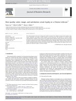
Bạn đang xem bản rút gọn của tài liệu. Xem và tải ngay bản đầy đủ của tài liệu tại đây (618.92 KB, 19 trang )
20
© 2000 by CRC Press LLC
MPEG System — Video, Audio,
and Data Multiplexing
In this chapter, we present the methods and standards requiring how to multiplex and synchronize
the MPEG-coded video, audio, and other data into a single bitstream or multiple bitstreams for
storage and transmission.
20.1 INTRODUCTION
ISO/IEC MPEG has completed work on the ISO/IEC 11172 and 13818 standards known as MPEG-1
and MPEG-2, respectively, which deal with the coding of digital audio and video signals. Currently,
ISO/IEC is working on ISO/IEC 14496 known as MPEG-4 that is object-based generic coding for
multimedia applications. As mentioned in the previous chapters, the MPEG-1, 2, and 4 standards
are designed as generic standards and as such are suitable for use in a wide range of audiovisual
applications. The coding part of the standards convert the digital visual, audio, and data signals to
the compressed formats that are represented as binary bits. The task of the MPEG system is focused
on multiplexing and synchronizing the coded audio, video, and data into a single bitstream or
multiple bitstreams. In other words, the digital compressed video, audio, and data are all first
represented as binary formats which are referred to as bitstreams, and then the function of system
is to mix the bitstreams from video, audio, and data together. For this purpose, several issues have
to be addressed by the system part of the standard:
• Distinguishing different data, such as audio, video, or other data;
• Allocating bandwidth during muxing;
• Reallocating or decoding the different data during demuxing;
• Protecting the bitstreams in error-prone media and detecting the errors;
• Dynamically multiplexing several bitstreams.
Additional requirements for the system should include extensibility issues, such as:
• New service extensions should be possible;
• Existing decoders should recognize and ignore data they cannot understand;
• The syntax should have extension capacity.
It should also be noted that all system-timing signals are included in the bitstream. This is the
big difference between digital systems and traditional analog systems in which the timing signals
are transmitted separately. In this chapter, we will introduce the concept of systems and give detailed
explanations for existing standards such as MPEG-2. However, we will not go through the standards
page by page to explain the syntax, we will pay more attention to the core parts of the standard
and the parts which always cause confusion during implementation. One of the key issues is system
timing. For MPEG-4, we will give a presentation of the current status of the system part of the
standards.
© 2000 by CRC Press LLC
20.2 MPEG-2 SYSTEM
The MPEG-2 system standard is also referred to as ITU-T Rec. H.222.0/ISO/IEC 13818-1
(ISO/IEC, 1996). The ISO document gives a very detailed description of this standard. A simplified
overview of this system is shown in Figure 20.1.
The MPEG-2 system coding is specified in two forms: the transport stream and the program
stream. Each is optimized for a different set of applications. The audio and video data are first
encoded by an audio and a video encoder, respectively. The coded data are the compressed
bitstreams, which follow the syntax rules specified by the video-coding standard 13818-2 and audio-
coding standard 13818-3. The compressed audio and video bitstreams are then packetized to the
packetized elementary streams (PES). The video PES and audio PES are coded by system coding
to the transport stream or program stream according to the requirements of the application.
The system coding provides a coding syntax which is necessary and sufficient to synchronize
the decoding and presentation of the video and audio information; at the same time it also has to
ensure that data buffers in the decoders do not overflow and underflow. Of course, buffer regulation
is also considered by the buffer control or rate control mechanism in the encoder. The video, audio,
and data information are multiplexed according to the system syntax by inserting time stamps for
decoding, presenting, and delivering the coded audio, video, and other data. It should be noted that
both the program stream and the transport stream are packet-oriented multiplexing. Before we
explain these streams, we first give a set of parameter definitions used in the system documents.
Then, we describe the overall picture regarding the basic multiplexing approach for single video
and audio elementary streams.
20.2.1 M
AJOR
T
ECHNICAL
D
EFINITIONS
IN
THE
MPEG-2 S
YSTEM
D
OCUMENT
In this section, the technical definitions that are often used in the system document are provided.
First, the major packet- and stream-related definitions are given.
Access unit:
A coded representation of a presentation unit. In the case of audio, an access
unit is the coded representation of audio frame. In the case of video, an access unit indicates
all the coded data for a picture, and any stuffing that follows it, up to but not including
the start of the next access unit. In other words, the access unit begins with the first byte
of the first start code. Except for the end of sequence, all bytes between the last byte of
the coded picture and the sequence end code belong to the access unit.
DSM
-
CC:
Digital storage media command and control.
Elementary stream
(
ES
)
:
A generic term for one of the coded video, coded audio, or other
coded bitstreams in PES packets. One elementary stream is carried in a sequence of PES
FIGURE 20.1
Simplified overview of system layer scope. (From ISO/IEC 13818-1, 1996. With permission.)
© 2000 by CRC Press LLC
packets with one and only one stream identification. This implies that one elementary
stream can only carry the same type of data, such as audio or video.
Packet:
A packet consists of a header followed by a number of contiguous bytes from an
elementary data stream.
Packet identification
(
PID
)
:
A unique integer value used to associate elementary streams
of a program in a single- or multiprogram transport stream. It is a 13-bit field, which
indicates the type of data stored in the packet payload.
PES packet:
The data structure used to carry elementary stream data. It contains a PES
packet header followed by PES packet payload
.
PES stream:
A PES stream consists of PES packets, all of whose payloads consist of data
from a single elementary steam, and all of which have the same stream identification.
Specific semantic constraints apply.
PES packet header:
The leading fields in the PES packet up to and not including the PES
packet data byte fields. Its function will be explained in the section on syntax description.
System target decoder
(
STD
)
:
A hypothetical reference model of a decoding process used
to describe the semantics of the MPEG-2 system-multiplexed bitstream.
Program-specific information
(
PSI
)
:
PSI includes normal data that will be used for demul-
tiplexing of programs in the transport stream by decoders. One case of PSI, the nonman-
datory network information table, is privately defined.
System header:
The leading fields of program stream packets.
Transport stream packet header:
The leading fields of program stream packets.
The following definitions are related to timing information:
Time stamp:
A term that indicates the time of a specific action such as the arrival of a byte
or the presentation of a presentation unit.
System clock reference
(
SCR
)
:
A Time stamp in the program stream from which decoder
timing is derived.
Elementary stream clock reference
(
ESCR
)
:
A time stamp in the PES stream from which
decoders of the PES stream may derive timing information.
Decoding time stamp
(
DTS
)
:
A time stamp that may be presented in a PES packet header
used to indicate the time when an access unit is decoded in the system target decoder.
Program clock reference
(
PCR
)
:
A time stamp in the transport stream from which decoder
timing is derived.
Presentation time stamp
(
PTS
)
:
A time stamp that may be presented in the PES packet
header used to indicate the time that a presentation unit is presented in the system target
decoder.
20.2.2 T
RANSPORT
S
TREAMS
The transport stream is a stream definition that is designed for communicating or storing one or
more programs of coded video, audio, and other kinds of data in lossy or noisy environments where
significant errors may occur. A transport stream combines one or more programs with one or more
time bases into a single stream. However, there are some difficulties with constructing and delivering
a transport stream containing multiple programs with independent time bases such that the overall
bit rate is variable. As in other standards, the transport stream may be constructed by any method
that results in a valid stream. In other words, the standards just specify the system coding syntax.
In this way, all compliant decoders can decode bitstreams generated according to the standard
syntax. However, the standard does not specify how the encoder generates the bitstreams. It is
possible to generate transport streams containing one or more programs from elementary coded
data streams, from program streams, or from other transport streams, which may themselves contain
© 2000 by CRC Press LLC
one or more programs. An important feature of a transport stream is that the transport stream is
designed in such a way that makes the following operations possible with minimum effort. These
operations include several transcoding requirements, including the following:
• Retrieve the coded data from one program within the transport stream, decode it, and
present the decoded results. In this operation, the transport stream is directly demulti-
plexed and decoded. The data in the transport stream are constructed in two layers: a
system layer and a compression layer. The system decoder decodes the transport streams
and demultiplexes them to the compressed video and audio streams that are further
decoded to the video and audio data by the video decoder and the audio decoder,
respectively. It should be noted that nonaudio/video data is also allowed. The function
of the transport decoder includes demultiplexing, depacketization, and other functions
such as error detection, which will be explained in detail later. This procedure is shown
in Figure 20.2.
•
Extract the transport stream packets from one program within the transport stream and
produce as the output a new transport stream that contains only that one program. This
operation can be seen as system-layer transcoding that converts a transport stream
containing multiple programs to a transport stream containing only a single program. In
this case, the remultiplexing operation may need the correction of PCR values to account
for changes in the PCR locations in the bitstream.
• Extract the transport stream packets of one or more programs from one or more transport
streams and produce as output of a new transport stream. This is another kind of
transcoding that converts selected programs of one transport stream to a different one.
• Extract the contents of one program from the transport stream and produce as output
another program stream. This is a transcoding that converts the transport program to a
program stream for certain applications.
•
Convert a program stream to a transport stream that can be used in a lossy communication
environment.
To answer the question of how to define the transport stream and then make the above
transcoding simpler and more efficient, we will begin by describing the technical detail of the
systems specification in the following section.
20.2.2.1 Structure of Transport Streams
As described earlier, the task of the transport stream coding layer is to allow one or more programs
to be combined into a single stream. Data from each elementary stream are multiplexed together
with timing information, which is used for synchronization and presentation of the elementary
FIGURE 20.2
Example of transport demultiplexing and decoding. (From ISO/IEC 13818-1, 1996. With
permission.)
© 2000 by CRC Press LLC
stream during decoding. Therefore, the transport stream consists of one or more programs such as
audio, video, and data elementary stream access units. The transport stream structure is a layered
structure. All the bits in the transport stream are packetized to the transport packets. The size of
transport packet is chosen to be 188 bytes, among which 4 bytes are used as the transport stream
packet header. In the first layer, the header of the transport packets indicates whether or not the
transport packet has an adaptation field. If there is no adaptation field, the transport payload may
consist of only PES packets or consist of both PES packets and PSI packets. Figure 20.3 illustrates
the case of containing PES packets only. If the transport stream carries both PES and PSI packets,
then the structure of transport stream is as shown in Figure 20.4 would result. If the transport stream
packet header indicates that the transport stream packet includes the adaptation field, then the
construct is as shown in Figure 20.5.
In Figure 20.5, the appearance of the optional field depends on the flag settings. The function
of adaptation field will be explained in the syntax section. Before we go ahead, however, we should
give a little explanation regarding the size of the transport stream packet. More specifically, why
is a packet size of 188 bytes chosen? Actually, there are several reasons. First, the transport packet
size needs to be large enough so that the overhead due to the transport headers is not too significant.
Second, the size should not be so large that the packet-based error correction code becomes
inefficient. Finally, the size 188 bytes is also compatible with ATM packet size which is 47 bytes;
one transport stream packet is equal to four ATM packets. So the size of 188 bytes is not a theoretical
solution but a practical and compromised solution.
FIGURE 20.3
Structure of transport stream containing only PES packets. (From ISO/IEC 13818-1, 1996.
With permission.)
FIGURE 20.4
Structure of transport stream containing both PES packets and PSI packets.
© 2000 by CRC Press LLC
20.2.2.2 Transport Stream Syntax
As we indicated, the transport stream is a layered structure. To explain the transport stream syntax
we start from the transport stream packet header. Since the header part is very important, it is the
highest layer of the stream. We describe it in more detail. For the rest, we do not repeat the standard
document and just indicate the important parts that we think may cause some confusion for readers.
The detail of other parts that are not covered here can be found from the MPEG standard document
(ISO/IEC, 1996).
Transport stream packet header
— This header contains four bytes that are assigned as eight parts:
The mnemonic in the above table means:
• The sync_byte is a fixed 8-bit field whose value is 0100 0111 (hexadecimal 47 = 71).
• The transport_error_indicator is a 1-bit flag, when it is set to 1, it indicates that at least
1 uncorrectable bit error exists in the associated transport stream packet. It will not be
reset to 0 unless the bit values in error have been corrected. This flag is useful for error
concealment purpose, since it indicates the error location. When an error exists, either
resynchronization or another concealment method can be used.
• The payload_unit_start_indicator is a 1-bit flag that is used to indicate whether the
transport stream packets carry PES packets or PSI data. If it carries PES packets, then
the PES header starts in this transport packet. If it contains PSI data, then a PSI table
starts in this transport packet.
• The transport_priority is a 1-bit flag which is used to indicate that the associated packet
is of greater priority than other packets having the same PID which do not have the flag
FIGURE 20.5
Structure of transport stream whose header contains an adaptation field.
Syntax No. of bits Mnemonic
sync_byte 8 bslbf
transport_error_indicator 1 bslbf
payload_unit_start_indicator 1 bslbf
transport_priority 1 bslbf
PID 13 uimsbf
transport_scrambling_control 2 bslbf
adaptation_field_control 2 bslbf
continuity_counter 4 uimsbf
bslbf Bitstream left bit first
unimsbf Unsigned integer, most significant bit first
© 2000 by CRC Press LLC
bit set to 1. The original idea of adding a flag to indicate the priority of packets comes
from video coding. The video elementary bitstream contains mostly bits that are con-
verted from DCT coefficients. The priority indicator can set a partitioning point that can
divide the data into a more important part and a less important part. The important part
includes the header information and low-frequency coefficients, and the less important
part includes only the high-frequency coefficients that have less effect on the decoding
and quality of reconstructed pictures.
• PID is a 13-bit field that provides information for multiplexing and demultiplexing by
uniquely identifying which packet belongs to a particular bitstream.
• The transport_scrambling_control is a 2-bit flag. 00 indicates that the packet is not
scrambled, the other three (01, 10, and 11) indicate that the packet is scrambled by a
user-defined scrambling method. It should be noted that the transport packet header and
adaptation field (when it is present) should not be scrambled. In other words, only the
payload of transport packets can be scrambled.
• The adaptation_field_control is a 2-bit indicator that is used to inform whether or not
there is an adaptation field present in the transport packet. 00 is reserved for future use:
01 indicates no adaptation field; 10 indicates that there is only an adaptation field and
no payload. Finally, 11 indicates that there is an adaptation field followed by a payload
in the transport stream packet.
• The continuity_counter is a 4-bit counter which increases with each transport stream
packet having the same PID.
From the header of the transport stream packet we can obtain information about future bits.
There are two possibilities; if the adaptation field control value is 10 or 11, then the bits following
the header are adaptation field; otherwise, the bits are payload. The information contained in the
adaptation field is described as follows.
Adaptation field
— The structure of the adaptation field data is shown in Figure 20.5. The
functionality of these headers is basically related to the timing and decoding of the elementary bit
steam. Some important fields are explained below:
• Adaptation field length is an 8-bit field specifying the number of bytes immediately
following it in the adaptation field including stuffing bytes.
• Discontinuity indicator is 1-bit flag which when it is set to 1 indicates that the discon-
tinuity state is true for the current transport packet. When this flag is set to 0, the
discontinuity is false. This discontinuity indicator is used to indicate two types of
discontinuities, system time-base discontinuities and continuity-counter discontinuities.
In the first type, this transport stream packet is the packet of a PID designed as a PCR-
PID. The next PCR represents a sample of a new system time clock for the associated
program. In the second type, the transport stream packet could be any PID type. If the
transport stream packet is not designated as a PCR-PID, the continuity counter may be
discontinuous with respect to the previous packet with the same PID or when a system
time-base discontinuity occurs. For those PIDs that are not designated as PCR-PIDs, the
discontinuity indicator may be set to 1 in the next transport stream packet with the same
PID, but will not be set to 1 in three consecutive transport stream packet with the same
PID.
• Random access indicator is a 1-bit flag that indicates the current and subsequent transport
stream packets with the same PID, containing some information to aid random access
at this point. Specifically, when this flag is set to 1, the next PES packet in the payload
of the transport stream packet with the current PID will contain the first byte of a video
sequence header or the first byte of an audio frame.