Impact of longitudinal slope, layout and loading on the braking process of an articulated vehicle
Bạn đang xem bản rút gọn của tài liệu. Xem và tải ngay bản đầy đủ của tài liệu tại đây (419.61 KB, 11 trang )
IMPACT OF LONGITUDINAL SLOPE, LAYOUT
AND LOADING ON THE BRAKING PROCESS
OF AN ARTICULATED VEHICLE
MIKHAIL P. MALINOVSKY1
Dr., Assoc. prof.,
EVGENY S. SMOLKO1
Student,
1
Moscow automobile and road construction state technical university (MADI), 64, Leningradsky prosp.,
Moscow, 125319, Russia
Abstract: Calculation of braking properties has always been one of the most important
stages in the design of any vehicle. With the advent of various active safety systems, such as
anti-lock braking systems, collision avoidance systems, automatic emergency braking systems,
mathematical models have become much more complicated, but the approach to studying the
braking process remains almost unchanged. The authors of the article note the imperfection of
modern methods of calculating the braking properties and offer a number of refinements that
allow for taking into account factors such as the longitudinal slope of the road, as well as the
layout and loading of the vehicle in relation to articulated vehicles with a semi-trailer and a
full trailer.
Keywords: special purpose vehicles; braking efficiency; pneumatic brake drive; active
safety; adhesion coefficient; weight redistribution; iterative method
Received: 06/12/2019
Accepted: 20/02/2020
Published online: 14/06/2020
I. INTRODUCTION
Evaluation of braking properties is one of the most important steps in calculating not only
traditional vehicle control systems [1], but also modern active safety systems, which include an
anti-lock system [2–8], electronic stability control [9–11], collision avoidance systems [12–19]
and automatic emergency braking systems [20–21]. When calculating the algorithms for the
systems mentioned above, they try to take into account the influence of the friction coefficient φ
on the braking properties of a vehicle, which has its own characteristics in the presence of
studded tires [22–23]. However, the currently existing methods and mathematical models, as a
rule, do not take into account the asynchrony of reaching the grip limit by wheels of different
axles, which is especially important for articulated vehicles [24–25]. An illiterate assessment of
the inhibitory properties leads to the adoption of erroneous decisions in the organization of
traffic [26] and, as a result, an increase in the mental tension of drivers [27].
In the traditional method of calculating the braking parameters, the balance of forces is
considered under separate action on the tractor and trailer [28], and therefore the influence of
factors such as loading from full mass mfull to curb mass mcurb and the effect of redistribution of
gravity under the deceleration action d, which increases with increasing center of mass h of the
62
INTERNATIONAL COOPERATION ISSUE OF TRANSPORTATION - Special Issue - No. 10
links of the road train, the real ratio of the maximum braking force Pbm developed by the braking
mechanisms, and the adhesion limit Ф, which can lead to a decrease in the specific forces γ i on
some axes, as well as to the transfer function of the brake mechanism Кb.
The brake system is designed for the full mass mfull, therefore, with a decrease in load, to
achieve the maximum steady-state deceleration dm, less braking force Pbm will be required.
When calculating the braking efficiency for curb mass m curb or partial load mpart, it is necessary
to take into account the decrease in the center of mass, which can be very significant for trailed
links.
Previously, the authors proposed refinements to take into account the redistribution of
gravity, but that did not take into account the longitudinal reaction in the coupling device [29–
32]. In this article, the authors propose refinements that take into account the influence of the
longitudinal inclination angle, as well as the layout and loading of the articulated vehicle on its
braking process, in particular, on wheel lock and longitudinal reaction in the coupling device.
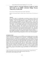
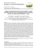
II. FORCE SCHEME AT THE BRAKING PROCESS
In the general case, when braking, the following forces act on the links of the articulated
vehicle (Fig. 1-2):
– the gravity G and the normal reactions opposing it on the wheels Ni and on the fifth
wheel Nfw;
– the braking forces Pbi and the inertia force m∙d opposing them;
– the resulting force in the coupling device Pfw/ht;
– rolling resistance forces on wheels Pfi;
– air resistance force Pw.
When calculating the braking process, the forces Pfi and Pw can be neglected, since they
create additional resistance and positively affect the braking efficiency. In addition, during
braking, the speed decreases, and the influence of these forces decreases. During emergency
braking, all wheels are theoretically reduced to sliding, therefore, the force is Pf=0, and rotating
masses (wheels, transmission and engine crankshaft) can be ignored.
Assumptions:
1) the dynamic radius of the wheel rw is considered equal to the static one; the change in rw
with increasing weight acting on the wheel is not taken into account;
2) the weight along the axes of the trolley is distributed evenly;
3) the longitudinal displacement of the center of gravity of the sprung masses under the
action of inertia is neglected due to its insignificance;
4) the coefficient of grip is constant in time and is evenly distributed over all the wheels of
INTERNATIONAL COOPERATION ISSUE OF TRANSPORTATION - Special Issue - No. 10
63
the articulated vehicle (φ=const);
5) after reaching the maximum clamping force of the friction surfaces, the braking forces
on the wheels have a constant value of Pbm, although in reality the braking process is
accompanied by heating of the friction surfaces, as a result of which the coefficient of friction
between the friction elements changes.
Fig. 1. Articulated vehicle with a semi-trailer. Force scheme
Fig. 2. Articulated vehicle with a full trailer. Force scheme
Initial data for calculation are given in the table 1, where:
– mtr, mst, mft – mass of tractor, semi-trailer, full trailer, respectively;
– m1,2,3,4 – mass attributable to this axis;
– mfw – mass attributable to the fifth wheel coupling device;
– Ltr, Lst, Lft – wheelbase of the tractor, semi-trailer, full trailer;
– ℓfw – longitudinal displacement of the fifth wheel coupling device;
– htr – height of the center of mass of the tractor;
– hfw – height of the fifth wheel coupling;
– hht – drawbar height of the towbar;
– rw – radius of the wheel;
64
INTERNATIONAL COOPERATION ISSUE OF TRANSPORTATION - Special Issue - No. 10
– ℓexp, ℓlev – shoulder of expanding force and length of the drive lever of the brake
mechanism, respectively;
– ffr – friction coefficient of the brake mechanism;
– SDtr, SDst, SDft – working area of the brake chambers of the tractor, semi-trailer, full trailer,
respectively;
– n1,2,3,4 – number of axles in the trolley.
Table 1. The given data
Parameter
GAZON NEXT C47R13
+ Chajka-Servis 938410
URAL NEXT 7470 +
PPO 22-23D UST 94651
mtr, kg
m1, kg
m2, kg
mst/ft, kg
mfw, kg
m3, kg
m4, kg
Ltr, m
ℓfw, m
Lst/ft, m
hfw/ht, m
htr, m
r w, m
ℓexp, m
ℓlev, m
ffr
SDtr, mm2
SDst/ft, mm2
n1
n2
n3
n4
8700
2300
6400
8500
3240
5260
–
4,5
0
8
1,1
0,835
0,419
0,27
0,205
0,4
9032
9032
1
1
1
–
16500
6000
10500
22050
8050
14000
–
5,5
0,12
12
1,32
1,03
0,6
0,38
0,18
0,3
12903
19355
1
2
2
–
KAMAZ-4310 +
SZAP-8305
curb mass full mass
8745
15205
4315
5020
4430
10185
4500
18000
–
1500
6000
3000
12000
4
–
4,327
0,96
1,04
1,16
0,59
0,38
0,18
0,25
15484
15484
1
2
1
2
In the design diagrams, the force acting in the coupling device is directed backward, since
this case is more favorable: firstly, the stability of movement increases (the likelihood of folding
the articulated vehicle decreases), and secondly, the effect of weight redistribution decreases.
However, due to the significant delay of the pneumatic brake drive of the trailed link relative to
that of the tractor, the vector of the mentioned force will be directed forward. In order to avoid
folding the articulated vehicle, a brake valve and a trailer brake control valve are used with
special characteristics that provide some force ahead of the braking of the trailer link relative to
the tractor. Most effectively the folding problem is solved by an electro-pneumatic brake drive
[33].
The equations of the resulting forces for the tractor, semi-trailer and full trailer,
INTERNATIONAL COOPERATION ISSUE OF TRANSPORTATION - Special Issue - No. 10
65
respectively:
F
= G tr sin + mtrd av − Pb1 − Pb 2 ;
tr
F
st
F
ft
= Gst sin + mst d av − Pb 3 ;
= G ft sin + mft dav − Pb3 − Pb 4 , N.
(1)
(2.1)
(2.2)
The equation of forces for determining the direction of the force acting in the fifth wheel
coupling of an articulated vehicle with a semi-trailer:
Pfw = Fst − Ftr , N.
(3.1)
The same for determining the direction of the force acting in the towing device of an
articulated vehicle with a full trailer:
Pht = Fft − Ftr , N.
(3.2)
Equations of moments for an articulated vehicle with a semi-trailer:
Mfw = 0 = N3Lst + Gst (h st sin − st cos ) + mst dh st − Pfw h fw ;
M3 = 0 = Nfw Lst − Gst (h st sin + (Lst − st )cos ) − mst dh st + Pfw h fw ;
M1 = 0 = N2Ltr + G tr (h tr sin − tr cos ) + mtrdh tr − Pfw h fw − G fw (Ltr − fw );
M2 = 0 = N1Ltr − G tr (h tr sin + (Ltr − tr )cos ) − mtrdh tr + Pfw h fw − G fw fw .
Equations of moments for an articulated vehicle with a semi-trailer:
M3 = 0 = N4Lft + G ft (h ft sin − ft cos ) + mft dh ft − Pht h ht ;
M4 = 0 = N3Lft − G ft (h ft sin + (Lft − ft )cos ) − mft dh ft + Pht h ht ;
M1 = 0 = N2Ltr + G tr (h tr sin − tr cos ) + mtrdh tr − Pht h ht ;
M2 = 0 = N1Ltr − G tr (h tr sin + (Ltr − tr )cos ) − mtrdh tr + Pht h ht .
III. STATIC REACTIONS
The articulated vehicle, which is stationary on a horizontal surface (ψ=0), is affected only
by gravity G and normal reactions on Ni wheels, id est d=0, Pbi=0, consequently, Pfw/ht=0. To
determine the weight per axis, it is necessary to solve the system of equations of moments
relative to each axis. Part of the gravity force Gfw=–Nfw from the semi-trailer is transmitted
through the fifth wheel coupling to the tractor, therefore it is advisable to first solve the system
of moment equations for the semi-trailer, and then to the tractor.
Thus, normal static reactions on the semi-trailer:
66
INTERNATIONAL COOPERATION ISSUE OF TRANSPORTATION - Special Issue - No. 10
G st st
G (L − st )
; N 0 fw = st st
, N.
L st
Lst
N 03 =
Normal static reactions on the full trailer:
N 04 =
G ft ft
G (L − ft )
; N 03 = ft ft
, N.
L ft
L ft
Normal static reactions on the tractor:
N 02 =
G tr tr + G fw (L tr − fw )
G (L − tr ) + G fw fw
; N 01 = tr tr
, N,
L tr
L tr
where Gfw=0 for an articulated vehicle with a full trailer.
Knowing the distribution of mass along the axes, you can determine the location of the
center of gravity along the longitudinal axis of each link:
tr = L tr
m2
m
m4
; st = L st 3 ; ft = L ft
, m.
m tr
m st
m ft
The results are given in the table 2.
Table 2. Coordinates of gravity centers
Parameter
GAZON NEXT C47R13
+ Chajka-Servis 938410
ℓtr, m
ℓst/ft, m
3,31
4,95
URAL NEXT 7470 +
PPO 22-23D UST
94651
3,5
7,62
KAMAZ-4310 +
SZAP-8305
curb mass
full mass
2,03
2,68
2,88
2,88
IV. BRAKING FORCES
The gear ratio of the brake mechanism of this axis:
K bi =
2 exp f fr lev
rw A d cam
,
where 2 is the number of brake pads;
ℓexp – expanding shoulder, m;
ffr – coefficient of friction;
ℓlev – length of drum brake drive lever, m;
rw – radius of the wheel, м;
A=0,82 – design coefficient (depending on the type of mechanism);
dcam=0,04 m – initial diameter of expansion brake cam.
INTERNATIONAL COOPERATION ISSUE OF TRANSPORTATION - Special Issue - No. 10
67
Maximum braking force on this axis:
Pbmi = k i K biSDi (pfin − 0,065) , N,
где ki=2∙ni – number of brake chambers per axle;
SDi – working area of brake chamber diaphragm, mm2;
pfin – final pressure (in this case, maximum pm), MPa.
V. WEIGHT REDISTRIBUTION
In addition to the gravity G and normal Ni reactions, the articulated vehicle during braking
on a slope is affected by the braking forces on the Pbi wheels, the inertia force m∙d and the
resulting force in the coupling device Pfw/ht. Normal reactions on the axes during braking are
found from the equations of moments.
For an articulated vehicle with a semi-trailer:
G st (st cos − h st sin ) − mst dh st + Pfw h fw
;
Lst
(4.1)
G st ((Lst − st )cos + h st sin ) + mst dh st − Pfw h fw
;
Lst
(5.1)
N3 =
N fw =
N2 =
G tr (tr cos − h tr sin ) − m tr dh tr + Pfw h fw + G fw (L tr − fw )
; (6.1)
L tr
N1 =
G tr ((L tr − tr ) cos + h tr sin ) + m tr dh tr − Pfw h fw + G fw fw
. (7.1)
L tr
For an articulated vehicle with a full trailer:
68
N4 =
G ft (ft cos − h ft sin ) − m ft dh ft + Pht h ht
;
L ft
(4.2)
N3 =
G ft ((L ft − ft )cos + h ft sin ) + m ft dh ft − Pht h ht
;
L ft
(5.2)
N2 =
G tr (tr cos − h tr sin ) − m tr dh tr + Pht h ht
;
L tr
(6.2)
N1 =
G tr ((L tr − tr )cos + h tr sin ) + m tr dh tr − Pht h ht
.
L tr
(7.2)
INTERNATIONAL COOPERATION ISSUE OF TRANSPORTATION - Special Issue - No. 10
VI. TRACTION LIMIT
The grip limit on this axis is determined:
Ф i = N i , Н.
(8)
The values of Pbmi and Фi on each axis are compared:
1. If Pbmi>Фi, then the wheels on this axis during braking reach the traction limit and are
blocked, which means that braking will be performed with maximum efficiency (γi=φ), and the
actual braking force PbiF=Фi.
2. If Pbmi<Фi, then it will not be possible to achieve wheel lock on this axis. Therefore, the
coupling properties of the tires will not be fully realized (γi<φ), while PbiF=Pbmi. In other words:
PbiF = min (Pbmi , i ) .
(9)
If wheel locks cannot be achieved over the entire range of φ, we can conclude that the
brake mechanisms on this axis are underloaded, and to increase the braking force, the size of the
brake chambers should be increased. If the wheels are locked over the entire range of φ, the
brake mechanisms are overloaded and the brake chambers should be reduced.
Next, the actual slowdown of the articulated vehicle is determined:
dF =
P
biF
, m/s2,
(10)
m av
where mav is the mass of the articulated vehicle.
Then PbiF and dF are substituted into expressions (1), (2.1), (2.2).
For an articulated vehicle, the task is solved only by the iterative method [34–35]: in order
to make up the equation of moments, it is necessary to determine the direction of the force in the
coupling device; to do which, you need to know the actual braking forces and the actual
deceleration of the articulated vehicle; for this, it is necessary to determine the grip limits; and
to determine those, it is necessary to solve the equation of moments.
At the initial stage, it is assumed that the actual braking forces on all axes are equal to the
limiting Pb=Pbm, respectively, the articulated vehicle slows down with the maximum
deceleration, possible according to the conditions of grip of the wheels to the road:
d = d m = g , m/s2.
The number of iterations is determined based on the required calculation accuracy.
From the equality Pbmi=Ni∙φ, we can determine the grip coefficient φlock, at which wheels
locking will begin on this axis. The lower the φlock, the less the tendency of the wheels to lock,
so the range on which there is no slipping increases. However, this task has a simple solution
only for a single vehicle. Consider a tractor unit (Pht=0):
INTERNATIONAL COOPERATION ISSUE OF TRANSPORTATION - Special Issue - No. 10
69
Pbm 2 =
Pbm1 =
m tr g(tr cos − h tr sin ) − m tr glock 2 h tr
lock 2 ;
L tr
m tr g((L tr − tr )cos + h tr sin ) + m tr glock1h tr
lock1 .
L tr
It turns out a system of quadratic equations:
2
− h tr lock
+ (tr cos − h tr sin ) lock 2 −
2
Pbm 2 L tr
=0;
m tr g
2
h tr lock
+ ((L tr − tr )cos + h tr sin ) lock1 −
1
Pbm1L tr
= 0.
m tr g
We are interested in a root with a positive root of discriminant. If the discriminant is equal
to zero, this means that the wheels lock will occur on the entire range of φ.
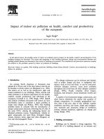
The calculation results are shown in Fig. 3.
Fig. 3. Dependence of the grip coefficient by locking on the slope and load
To solve the task mentioned above for an articulated vehicle, it is necessary to apply an
iterative method.
VII. CONCLUSION
The technique proposed by the authors allows to estimate the grip coefficient at which the
axles of the vehicle begin to lock, taking into account the longitudinal slope, load and reaction
in the coupling device. Analysis of the results shows the following:
70
INTERNATIONAL COOPERATION ISSUE OF TRANSPORTATION - Special Issue - No. 10
1. With a decrease in load, the tendency of the wheels to lock increases.
2. On the downhill, the effect of the redistribution of gravity increases the tendency of the
front wheels to lock decreases, and in the rear – vice versa.
3. For tractors with a fifth wheel coupling, the effect of the redistribution of gravity is
leveled, since the rear carriage has the weight transmitted from the semi-trailer through the
coupling device.
References
1. Pavlov V.V. Proektirovochnye raschjoty transportnyh sredstv special'nogo naznachenija
[Design calculations of special vehicles]. Moscow, MADI, 2014, 116 p.
2. Dygalo V.G., Revin A.A. Trudy NGTU im. R.E. Alekseeva, 2011, no. 3, pp. 146-155.
3. Kristal'nyj S.R., Popov N.V., Fomichjov V.A. Vestnik MADI, 2012, issue 2, pp. 10a-17.
4. Dygalo V.G., Kotov V.V., Revin A.A. Izvestija Volgogradskogo gosudarstvennogo
tehnicheskogo universiteta. Serija: Nazemnye transportnye sistemy, 2013, vol. 6, no. 10, pp. 1316.
5. Gladov G.I., Zajcev S.V., Kotovich S.V. Konstrukcii transportnyh sredstv special'nogo
naznachenija [Construction of special vehicles]. Moscow, MADI, 2014, 164 p.
6. Kristal'nyj S.R., Popov N.V., Fomichev V.A. Avtotransportnoe predprijatie, 2014, no. 6, pp.
50-53.
7. Dygalo V.G., Kotov V.V., Dygalo L.V., Revin A.A. Izvestija Volgogradskogo
gosudarstvennogo tehnicheskogo universiteta. Serija: Nazemnye transportnye sistemy, 2014,
vol. 9, no. 19, pp. 16-20.
8. Revin A.A., Dygalo V.G., Judina A.A., Dygalo L.V. Jenergo- i resursosberezhenie:
promyshlennost' i transport, 2016, no. 4, pp. 7-11.
9. Kristal'nyj S.R., Toporkov M.A., Fomichjov V.A., Popov N.V. Avtomobil'. Doroga.
Infrastruktura, 2015, No. 2, p. 2.
10. Ivanov A.M., Kristal'nyj S.R., Popov N.V., Fomichjov V.A., Sitnikov F.V. Avtomobil'.
Doroga. Infrastruktura, 2017, no. 1, p. 5.
11. Ivanov A.M., Kristal'nyj S.R., Popov N.V., Shadrin S.S. Intellektual'nye sistemy pomoshhi
voditelju. Tehnicheskie trebovanija i metody ispytanij [Intelligent driver assistance systems.
Technical requirements and test methods]. Moscow, MADI, 2019, 100 p.
12. Gladov G.I., Malinovskij M.P. Zhurnal avtomobil'nyh inzhenerov, 2009, no. 2, pp. 30-33.
13. Malinovskij M.P., Gladov G.I. Avtomobil'naja promyshlennost', 2009, no. 9, pp. 21-26.
14. Popov A.I., Kotenko I.V., Fransis O.O. Vestnik MADI, 2011, no. 3, pp. 12a-16.
15. Spinov A.R., Popov A.I., Kotenko I.V., Fransis O.O. Avtotransportnoe predprijatie, 2011,
no. 10, pp. 42-45.
16. Popov A.I., Spinov A.R., Kotenko I.V., Fransis O.O., Naddennaja E.A. Zhurnal
INTERNATIONAL COOPERATION ISSUE OF TRANSPORTATION - Special Issue - No. 10
71
avtomobil'nyh inzhenerov, 2011, no. 6, pp. 28-31.
17. Ivanov A.M., Solncev A.N., Spinov A.R., Shadrin S.S. Zhurnal avtomobil'nyh inzhenerov,
2013, no. 6, pp. 36-39.
18. Elistratov V.V., Bezrukov S.I., Stenin P.G. Avtomobil'naja promyshlennost', 2014, no. 1, pp.
25-28.
19. Elistratov V.V., Bezrukov S.I., Stenin P.G., Klimakov V.S. Sovremennye problemy nauki i
obrazovanija, 2014, no. 2, p. 12.
20. Ivanov A.M., Kristal'nyj S.R., Popov N.V., Toporkov M.A., Isakova M.I. Trudy NGTU im.
R.E. Alekseeva, 2018, no. 2, pp. 146-155.
21. Ivanov A.M., Kristal'nyj S.R., Popov. N.V. Sistemy avtomaticheskogo jekstrennogo
tormozhenija [Automatic emergency braking systems]. Moscow, MADI, 2018, 180 p.
22. Shadrin S.S., Ivanov A.M. Izvestija Moskovskogo gosudarstvennogo tehnicheskogo
universiteta MAMI, 2014, vol. 1, no. 3, pp. 65-68.
23. Ivanov A.M., Kristal'nyj S.R., Popov N.V., Fomichjov V.A. Zhurnal avtomobil'nyh
inzhenerov, 2017, no. 6, pp. 14-21.
24. Godzhaev Z.A., Izmajlov A.Ju., Miholap L.A. Sel'skohozjajstvennye mashiny i tehnologii,
2017, no. 6, pp. 3-8.
25. Godzhaev Z.A., Izmajlov A.Ju., Miholap L.A. Fundamental'nye i prikladnye problemy
tehniki i tehnologii, 2017, no. 4-1, pp. 104-110.
26. Malinovskij M.P., Zhuravleva A.Ju. Avtomobil'. Doroga. Infrastruktura, 2016, No. 4, p. 10.
27. Malinovskij M.P. Avtomobil'. Doroga. Infrastruktura, 2018, No. 4, p. 3.
28. Petrenko A.M. Metodicheskie ukazanija k laboratornym rabotam po discipline «Teorija
special'nyh transportnyh sredstv» [Guidelines for laboratory work in the discipline "Theory of
special vehicles"]. Moscow, MADI, 2003, Part 1, 54 p.
29. Gorelov V.A., Padalkin B.V., Chudakov O.I. Nauka i obrazovanie: nauchnoe izdanie
MGTU im. N.Je. Baumana, 2016, no. 12, pp. 1-17.
30. Gladov G.I., Petrenko A.M. Special'nye transportnye sredstva: Teorija [Special vehicles:
Theory]. Moscow, Akademkniga, 2006, 215 p.
31. Smolko E.S. Avtomobil'. Doroga. Infrastruktura, 2019, no. 4.
32. Petrenko A.M. Ustojchivost' special'nyh transportnyh sredstv [Stability of special vehicles].
Moscow, MADI, 2013, 41 p.
33. Malinovsky M.P. Sistemy upravleniya kolesnyh mashin [Control systems of wheeled
machines]. Moscow, MADI, 2018, 100 p.
34. Malinovskij M.P. Avtomobil'naja promyshlennost', 2011, No. 5, pp. 33-35.
35. Dygalo V.G., Revin A.A. Izvestija Volgogradskogo gosudarstvennogo tehnicheskogo
universiteta. Serija: Nazemnye transportnye sistemy, 2013, Vol. 7, No. 21, pp. 10-16.
72
INTERNATIONAL COOPERATION ISSUE OF TRANSPORTATION - Special Issue - No. 10