Effect of welding speed on the mechanical properties of friction stir welded aluminium alloy 5083
Bạn đang xem bản rút gọn của tài liệu. Xem và tải ngay bản đầy đủ của tài liệu tại đây (1.25 MB, 4 trang )
Physical sciences | Engineering
Doi: 10.31276/VJSTE.62(3).45-48
Effect of welding speed on the mechanical properties
of friction stir welded aluminium alloy 5083
Tran Hung Tra1*, Huynh Minh Tu2
1
Nha Trang University
HCMC University of Technology and Education
2
Received 6 January 2020; accepted 9 June 2020
Abstract:
The influence of welding speed on the properties of friction stir welded aluminium alloy 5083 was explored. The
effects of various welding regimes on the defect formation, hardness distribution, tensile strength, and bending
strength of the joint were experimentally investigated. Kissing bond defects were prevalent in the joint, however,
this kissing bond was eliminated at high welding rates. The welded zone was softened significantly; all the tensile
specimens were fractured in the welding zone with shear mode. The tensile strength of the joint reached 85% of
the base aluminium alloy 5083 while the bending ductility of the joint was higher than that of base aluminium
alloy 5083.
Keywords: aluminium alloy 5083, defects, friction stir welding, mechanical properties.
Classification number: 2.3
Introduction
Aluminium alloys possess high specific strength and
are suitable for high-speed vehicles and among other
applications. Aluminium alloy 5083 (abbreviated as
AA5083) is an advanced alloy with excellent corrosive
resistance; thus, this alloy is used dominantly in shipbuilding.
One of the significant challenges in using aluminium alloys
is associated with their low weldability. Recently, friction
stir welding (FSW) has emerged as a new method for
welding aluminium alloys [1-7]. In FSW, the tool heats and
moves the metal beneath the tool shoulder to produce the
joint [8, 9]. During the FSW process, the microstructure
in the welded zone dramatically recrystallizes through
the interaction between the tool geometry and welding
parameters. Thus, the welded zone becomes inhomogeneous
and possesses varied properties [2-3]. Even though this
welding technology possesses several preeminent points,
application of this technology is still quite limited due to the
deficiency of equipment (especially in the case of Vietnam).
In this work, which is based on the NTU-FSW equipment
at the Friction Research Center, Nha Trang University, the
*
FSW butt-joint of AA5083 plate with 3.0 mm thickness
is investigated experimentally and the effect of various
welding regimes on the mechanical properties of the joint
is evaluated.
Materials and experiments
The AA5083 plates with 3 mm thickness (Korea)
were butt joined by the NTU-FSW machine in Friction
Stir Welding Lab of Nha Trang University. Two AA5083
plates were joined by a tool with a concave shoulder and a
truncated probe. The probe of the tool possessed a 4.0 mm
diameter at its middle (with respect to length) and was 2.8
mm in height. The tilt angle of the pin was set at 2.0 deg.
Various regimes of welding speed rates (denoted as WSR,
mm/rev) were performed to fabricate the joints. The WSR
defined as the ratio of weld speed and rotation speed. The
microstructure of the welded zone and the base AA5083
was observed by an optical microscope (Olympus, Japan).
The hardness property in and around the welded zone was
measured by the HM-125 equipment (Japan) using 100 gf
loading. Both the tensile specimens and bending specimens
Corresponding author: Email:
September 2020 • Volume 62 Number 3
Vietnam Journal of Science,
Technology and Engineering
45
Physical Sciences | Engineering
were tested by the 3366 Instron (Instron, USA) at a constant
strain rate of 10-3/s. Here, the tensile specimen geometry
was designed based on the standards ASTM E08; the
bending specimen geometry relied on ASTM E290. Here the
tested specimens were manufactured such that the loading
direction was perpendicular to the welding direction,
as shown in Fig. 1. Tables 1&2 show a data summary of
the chemical composition and mechanical properties of
AA5083, respectively.
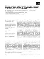
Fig. 2. The cross-section microstructure of the FSW fabricated
at WSR = 0.71 mm/rev: base alloy (I), region (II), region (III),
and region (IV).
Fig. 1. The geometry of the tensile specimen (ASTM E290),
dimension in mm.
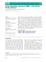
Fig. 3. Tunnel defect and kissing bond defect in the joints (AV
and RE are abbreviations of the advancing side and retreating
side, respectively).
Table 1. The chemical composition of AA5083, wt. %
Element
Al
Mg
Mn
Percentage
(%)
balance 4.0-4.9 0.4-1
Cu
Si
Zn
Mn
Ti
Cr
Max
0.1
Max
0.4
Max
0.25
Max
0.3
Max
0.05-0.25
0.15
Table 2. The mechanical properties of AA5083 aluminium alloy.
Mechanical
properties
Yield
strength
(MPa)
Tensile
strength
(MPa)
Elongation
(%)
Hardness
(HRB)
Elastic
modulus
(GPa)
Poisson
ratio
Value
190
300
16
50
70.3
0.33
Results and discussion
Several welding speed rates were used to fabricate the
joints. Afterwards, the defects formations and mechanical
properties of the FSW joint were investigated. The typical
microstructure of the FSW AA5083 (fabricated at WSR=0.71
mm/rev.) is presented in Fig. 2. It can be seen that the welded
zone is characterized by dynamic recrystallization (Fig. 2).
The grain size in the welded zone was refined significantly.
The average grain size diameter in the stirred zone was
about 10 µm, whereas the grain size of the base AA5083
was about 40 µm (see Fig. 2(I) and Fig. 2(IV)). The grain of
the heat-affected zone (HAZ) was similar to that of the base
alloy 5083, see Fig. 2(II&III).
46
Vietnam Journal of Science,
Technology and Engineering
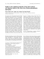
Fig. 4. Hardness distribution across the welding.
In the FSW, both the tunnel defect (see Fig. 3A) and
kissing bond defect (see Fig. 3B) were found in the joints.
The kissing bond was found to be dominant. The obtained
joint was free of defects under the high WSR regime (WSR
= 0.71 mm/rev).
The hardness distributions measured at the middle-line
of the cross-sections are shown in Fig. 4 as a function of
the WSR. For all the welding regimes, the material in the
welded region was softened remarkably. This softened zone
must be related to degradation of the material induced by the
welding temperature. The lowest hardness took place in the
September 2020 • Volume 62 Number 3
Physical sciences | Engineering
stirred zone where the peak welding temperature is located.
The effect of the welding regime on the hardness of the joint
seems to be unremarkable. The width of the softened zones
(see Fig. 4) also seemed to be independent of WSR.
Fig. 5. Tensile specimens and the tensile fracture locations (the
dash lines present the tool shoulder).
Fig. 6. Shear mode fracture of tensile specimens.
Fig. 7. Bending strength of the joint.
Fig. 8. Tensile strength and elongation of the joint.
Fig. 9. Bended FSW specimens under various WSR.
To evaluate the tensile properties of the joint, the tensile
specimens were extruded from the FSW plate and tested by
the 3366 Instron with a constant loading strain rate of 10-3/s.
For all cases, the specimens were fractured in the welded
zone (see Fig. 5) with a typical shear mode (see Fig. 6).
The fracture locations occurred in the lowest hardness zone
(Figs. 5 and 4). This fact implies that the effect of welding
temperature on the degradation of the welded zone seems to
be inevitable.
The ultimate tensile strength and the fracture elongation
of the FSW are plotted in Fig. 7. For all welding regimes,
in comparison to the base AA5083, the tensile properties of
the FSW alloys degraded remarkably. The highest tensile
strength and ductility was obtained at a WSR around 0.6
mm/rev. Here, the ultimate strength and fracture elongation
of the FSW alloys were about 85% and 57% that of the
base AA5083, respectively. It should be noted that at low
welding rates, a tunnel defect appeared in the joint (see
Fig. 3A). However, high values of WSR could lead to an
incomplete joint.
The results of bending strength and bending ductility
of the FSW alloys under the various welding regimes are
shown in Figs. 8&9. In all cases, the bending strength of the
September 2020 • Volume 62 Number 3
Vietnam Journal of Science,
Technology and Engineering
47
Physical Sciences | Engineering
FSW was lower than that of the base AA5083. However,
the bending ductility of the FSWs was mostly higher than
that of the base alloy. It should be noted that the joint was
cracked in the stirred zone (at the bottom face) at a low WSR
(see Fig. 9). Generally, the bending strength and bending
ductility of the FSW alloys are about 86% and 114% that of
base AA5083, respectively.
In summary, the kissing bond maintained a prominent
factor in the strength of the FSW AA5083. The joint can be
obtained with high strength and ductility. Even though the
strength of the joint degraded dramatically in comparison to
that of the base AA5083, the bending ductility of the joint
improved remarkably.
Conclusions
The FSW of AA5083 was successfully fabricated and
the effect of welding speed rate on its defects, hardness,
tensile, and bending properties was investigated. The
kissing bond defect was found to be dominant in the joint
but all the defects could be eliminated at high welding rates.
The 0.71 mm/rev WSR was found to be a suitable regime to
obtain a good joint. The strength of the joint reached 85%
that of the base AA5083 and the bending ductility improved
significantly.
The authors declare that there is no conflict of interest
regarding the publication of this article.
48
Vietnam Journal of Science,
Technology and Engineering
References
[1] M. Gene (2002), The welding of aluminium and its alloys,
Woodhead Publishing Ltd, Cambridge England.
[2] Z.Y. Ma (2008) “Friction stir processing technology: a
review”, Metallurgical and Materials Transactions, 37A, pp.642-658.
[3] R.S. Mishra, M.W. Mahoney editors (2007), Friction stir
welding and processing, ASM International.
[4] D.D. Hao, M. Okazaki, T.H. Tra, Q.H. Nam (2019), “Defects
morphology in the dissimilar friction stir welded T-lap joints of
AA7075 and AA5083”, Advances in Engineering Research and
Application, pp.210-216, DOI: 10.1007/978-3-030-04792-4_29.
[5] Tran Hung Tra, Masakazu Okazaki (2017), “Creep-fatigue
cracking near the welded interface in friction welding dissimilar
superalloys INCONEL 718 and MAR-M247”, Metallurgical and
Materials Transactions A, 48, pp.3692-3701.
[6] Duong Dinh Hao, Tran Hung Tra (2016), “Effects of friction
stir welding parameters on the mechanical properties of AA7075-T6”,
Archives of Materials Science and Engineering, 77(2), pp.58-64.
[7] Tran Hung Tra, Masakazu Okazaki, Kenji Suzuki (2012),
“Fatigue crack propagation behavior of friction stir welding AA 6063T5: residual stress and microstructure effect”, International Journal
of Fatigue, 43, pp.23-29.
[8] M. Shiva chander, P. Satish Kumar, Aruri Devaraju (2018),
“Influence of tool rotational speed and pin profile on mechanical and
microstructural characterization of friction stir welded 5083 aluminium
alloy”, Material Today: Proceedings, 5(2), Part 1, pp.3518-3523.
[9] K. Aruna Prabhaa Prasad, Kumar Puthab Balla, Srinivasa
Prasad (2018), “Effect of tool rotational speed on mechanical properties
of aluminium alloy 5083 weldments in friction stir welding”, Material
Today: Proceedings, 5(9), Part 3, pp.18535-18543.
September 2020 • Volume 62 Number 3