Finite element analysis and design of steel and steel concrete composite bridges ( PDFDrive )
Bạn đang xem bản rút gọn của tài liệu. Xem và tải ngay bản đầy đủ của tài liệu tại đây (15.08 MB, 0 trang )
FINITE ELEMENT
ANALYSIS
AND DESIGN
OF STEEL AND
STEEL–CONCRETE
COMPOSITE
BRIDGES
This page intentionally left blank
FINITE ELEMENT
ANALYSIS
AND DESIGN
OF STEEL AND
STEEL–CONCRETE
COMPOSITE
BRIDGES
by
EHAB ELLOBODY
Professor, Department of Structural Engineering,
Faculty of Engineering, Tanta University, Egypt
AMSTERDAM • BOSTON • HEIDELBERG • LONDON
NEW YORK • OXFORD • PARIS • SAN DIEGO
SAN FRANCISCO • SINGAPORE • SYDNEY • TOKYO
Butterworth-Heinemann is an imprint of Elsevier
Butterworth-Heinemann is an imprint of Elsevier
225, Wyman Street, Waltham, MA 01803, USA
The Boulevard, Langford Lane, Kidlington, Oxford OX5 1 GB, UK
First edition 2014
Copyright © 2014 Elsevier Inc. All rights reserved
No part of this publication may be reproduced, stored in a retrieval system or transmitted in
any form or by any means electronic, mechanical, photocopying, recording or otherwise
without the prior written permission of the publisher.
Permissions may be sought directly from Elsevier’s Science & Technology Rights
Department in Oxford, UK: phone (+44) (0) 1865 843830; fax (+44) (0) 1865 853333;
email: Alternatively you can submit your request online by
visiting the Elsevier web site at and selecting
Obtaining permission to use Elsevier material.
Notice
No responsibility is assumed by the publisher for any injury and/or damage to persons or
property as a matter of products liability, negligence or otherwise, or from any use or
operation of any methods, products, instructions or ideas contained in the material herein.
Because of rapid advances in the medical sciences, in particular, independent verification of
diagnoses and drug dosages should be made.
Library of Congress Cataloging-in-Publication Data
Ellobody, Ehab, author.
Finite element analysis and design of steel and steel-concrete composite bridges / by Ehab
Ellobody. – First edition.
pages cm
Includes bibliographical references and index.
ISBN 978-0-12-417247-0
1. Iron and steel bridges–Design and construction. 2. Concrete bridges–Design and
construction. 3. Finite element method. I. Title.
TG380.E45 2015
624.20 5–dc23
2014011942
British Library Cataloguing in Publication Data
A catalogue record for this book is available from the British Library
For information on all Butterworth-Heinemann publications
visit our web site at store.elsevier.com
Printed and bound in USA
14 15 16 17 18
10
ISBN: 978-0-12-417247-0
9
8 7
6 5
4
3 2
1
CONTENTS
1. Introduction
1.1 General remarks
1.2 Types of steel and steel-concrete composite bridges
1.3 Literature review of steel and steel-concrete composite bridges
1.4 Finite element modeling of steel and steel-concrete composite bridges
1.5 Current design codes of steel and steel-concrete composite bridges
References
2. Nonlinear Material Behavior of the Bridge Components
2.1 General remarks
2.2 Nonlinear material properties of structural steel
2.3 Nonlinear material properties of concrete
2.4 Nonlinear material properties of reinforcement bars
2.5 Nonlinear material properties of prestressing tendons
2.6 Nonlinear behavior of shear connection
References
3. Applied Loads and Stability of Steel and Steel-Concrete
Composite Bridges
1
1
7
20
39
41
42
47
47
48
62
73
78
82
107
113
3.1 General remarks
3.2 Dead loads of steel and steel-concrete composite bridges
3.3 Live loads on steel and steel-concrete composite bridges
3.4 Horizontal forces on steel and steel-concrete composite bridges
3.5 Other loads on steel and steel-concrete composite bridges
3.6 Load combinations
3.7 Design approaches
3.8 Stability of steel and steel-concrete composite plate girder bridges
3.9 Stability of steel and steel-concrete composite truss bridges
3.10 Design of bolted and welded joints
3.11 Design of bridge bearings
References
113
114
116
127
136
155
161
166
190
193
209
220
4. Design Examples of Steel and Steel-Concrete Composite Bridges
221
4.1 General remarks
4.2 Design example of a double-track plate girder deck railway steel bridge
4.3 Design example of a through truss highway steel bridge
221
222
263
v
vi
Contents
4.4 Design example of a highway steel-concrete composite bridge
4.5 Design example of a double-track plate girder pony railway steel bridge
4.6 Design example of a deck truss highway steel bridge
5. Finite Element Analysis of Steel and Steel-Concrete
Composite Bridges
5.1 General remarks
5.2 Choice of finite element types for steel and steel-concrete composite
bridges
5.3 Choice of finite element mesh for the bridges and bridge components
5.4 Material modeling of the bridge components
5.5 Linear and nonlinear analyses of the bridges and bridge components
5.6 Riks method
5.7 Modeling of initial imperfections and residual stresses
5.8 Modeling of shear connection for steel-concrete composite bridges
5.9 Application of loads and boundary conditions on the bridges
References
6. Examples of Finite Element Models of Steel Bridges
6.1 General remarks
6.2 Previous work
6.3 Finite element modeling
6.4 Finite element modeling
6.5 Finite element modeling
6.6 Finite element modeling
References
and
and
and
and
results
results
results
results
of example
of example
of example
of example
1
2
3
4
7. Examples of Finite Element Models of Steel-Concrete
Composite Bridges
7.1 General remarks
7.2 Previous work
7.3 Finite element modeling and results of example 1
7.4 Finite element modeling and results of example 2
7.5 Finite element modeling and results of example 3
References
Index
339
364
405
469
469
470
496
501
516
527
540
543
551
553
555
555
555
567
575
582
587
598
601
601
602
618
626
632
638
641
CHAPTER
1
Introduction
1.1 GENERAL REMARKS
Steel and steel-concrete composite bridges are commonly used all over the
world, owing to the fact that they combine both magnificent aesthetic
appearance and efficient structural competence. Their construction in a
country not only resembles the vision and inspiration of their architects
but also represents the country’s existing development and dream of a better
future. Compared to traditional reinforced concrete (RC) bridges, steel
bridges offer many advantages, comprising high strength-to-self weight
ratio, speed of construction, flexibility of construction, flexibility to modify,
repair and recycle, durability, and artistic appearance. The high strength-toself weight ratio of steel bridges minimizes dead loads of the bridges, which is
particularly beneficial in poor ground conditions. Also, the high strength-toself weight ratio of steel bridges makes it easy to transport, handle, and erect
the bridge components. In addition, it facilitates very shallow construction
depths, which overcome problems with headroom and flood clearances, and
minimizes the length of approach ramps. Furthermore, high strength-to-self
weight ratio of steel bridges permits the erection of large components, and in
special circumstances, complete bridges may be installed in quite short
periods. The speed of construction of steel bridges is attributed to the fact
that most of the bridge components can be prefabricated and transported
to the construction field, which reduces working time in hostile environments. The speed of construction of steel bridges also reduces the durations
of road closures, which minimizes disruption around the area of construction. Flexibility of construction of steel bridges is attributed to the fact
that the bridges can be constructed and installed using different methods
and techniques. Installation may be conducted by cranes, launching,
slide-in techniques, or transporters. Steel bridges give contractors the flexibility in terms of erection sequence and program. The bridge components
can be sized to suit access restrictions at the site, and once erected, the steel
girders provide a platform for subsequent operations. Flexibility to modify,
repair, and recycle steel bridges is a result of the ability to modify the current
status of the bridges such as widening the bridges to accommodate more
lanes of traffic. Also, steel bridges can be repaired or strengthened by adding
Finite Element Analysis and Design of Steel
and Steel–Concrete Composite Bridges
Copyright © 2014 Elsevier Inc.
All rights reserved.
1
2
Ehab Ellobody
steel plates or advanced composite laminates to carry more traffic loads. In
addition, if for any reason, such as end of their life of use or change of environment around the area, steel bridges can be recycled. Steel bridges are
durable bridges, provided that they are well designed, properly maintained,
and carefully protected against corrosion. Finally, steel bridges can fit most of
the complex architecture designs, which in some cases are impossible to
accommodate using traditional RC bridges.
Highway bridges made of RC slabs on top of the steel beams can be efficiently designed as composite bridges to get the most benefit from both the
steel beams and concrete slabs. Steel-concrete composite bridges offer additional advantages to the aforementioned advantages of steel bridges. Compared to steel bridges, composite bridges provide higher strength, higher
stiffness, higher ductility, higher resistance to seismic loadings, full usage
of materials, and particularly higher fire resistance. However, these advantages are maintained, provided that the steel beams and concrete slabs are
connected via shear connectors to transmit shear forces at the interface
between the two components. This will ensure that the two components
act together in resisting applied traffic loads on the bridges, which will result
in significant increases in the allowable vehicular weight limitations, ability
to transport heavy industrial and construction equipment, and possibility to
issue overload permits for specialized overweight and oversized vehicles.
One of the main advantages of having steel beams acting together with concrete slabs in composite bridges is that premature possible failures of the two
separate components are eliminated. For example, one of the primary modes
of failure for concrete bridges is cracking of the concrete slabs and beams in
tension, while for the steel bridges, the possible modes of failure are the formation of plastic hinges and the buckling of webs or flanges. By having the
steel beams work together with the concrete slab, the whole slab will be
mainly subjected to compressive forces, which reduces the possibility of tensile cracking. On the other hand, the presence of the concrete slab on top of
the steel beams eliminates the buckling of the top flange of the steel beams.
Efficient design of steel-concrete composite bridges can ensure that both the
steel beams and concrete slabs work together in resisting applied traffic loads
until failure occurs in both components, preferably at the same time, to get
the maximum benefit from both components.
Numerous books were found in the literature highlighting different
aspects of design for steel and steel-concrete composite bridges; for examples, see [1.1–1.11]. The books highlighted the problems associated with
the planning, design, inspection, construction, and maintenance of steel
Introduction
3
and steel-concrete composite bridges. Overall, the books discussed the basic
concepts and design approaches of the bridges, design loads on the bridges
from either natural or traffic-induced forces, and design of different components of the bridges. On the other hand, numerous finite element books are
found in the literature; for examples, see [1.12–1.18], explaining finite element method as a widely used numerical technique for solving problems in
engineering and mathematical physics. The books [1.12–1.18] were written
to provide basic learning tools for students mainly in civil and mechanical
engineering classes. The books [1.12–1.18] highlighted the general principles of finite element method and the application of this method to solve
practical problems. However, limited investigations, with examples detailed
in [1.19, 1.20], are found in the literature in which researchers used finite
element method in analyzing case studies related to steel and steel-concrete
composite bridges. Recently, with continuing developments of computers
and solving and modeling techniques, researchers started to detail the use of
finite element method to analyze steel and steel-concrete composite bridges,
with examples presented in [1.21, 1.22]. Also, extensive experimental and
numerical research papers were found in the literature highlighting finite
element analysis of steel and steel-concrete composite bridges, which will
be detailed in Section 1.3. However, up-to-date, there are no detailed books
found in the literature addressing both finite element analysis and design of
steel and steel-concrete composite bridges, which is credited to this book.
The current book will present, for the first time, explanation of the latest
finite element modeling approaches specifically as a complete piece work
on steel and steel-concrete composite bridges. This finite element modeling
of the bridges will be accompanied by design examples for steel and steelconcrete composite bridges calculated using current codes of practice.
There are many problems and issues associated with finite element
modeling of steel and steel-concrete composite bridges in the literature that
students, researchers, designers, practitioners, and academics need to address.
Incorporating nonlinear material properties of the bridge components in
finite element analyses has expanded tremendously over the last decades.
In addition, computing techniques are now widely available to manipulate
complicated analyses involving material nonlinearities of the bridge components. This book will highlight the latest techniques of modeling nonlinear
material properties of the bridge components. Also, simplified analytic solutions were derived to predict the distribution of forces and stresses in different bridge components based on many assumptions and limitations.
However, accurate analyses require knowledge of the actual distribution
4
Ehab Ellobody
of forces and stresses in the component members, which is the target of the
nonlinear finite element modeling approach detailed in this book. In addition, in case of steel-concrete composite bridges, if the slab cracks under
heavy traffic loads or the steel beam yields or buckles, it becomes extremely
important to know the location of failure, the postfailure strength of the
component that has failed, and the manner in which the forces and stresses
will redistribute themselves owing to the failure. Once again, traditional
simplified analyses cannot account for these complex failure modes because
no interaction between bridge components was considered. The finite element modeling approach aimed in this book will capture all possible failure
modes associated with steel-concrete composite bridges. It should also be
noted that while simplified design methods have been developed to predict
the ultimate capacity of steel bridges or their components, none of these
methods adequately predicts the structural response of the bridge in the
region between design load levels and ultimate capacity load levels. Therefore, the proposed finite element modeling approach will reliably predict
both the elastic and inelastic responses of a bridge superstructure as well
as the structural response in the region between the design limit and the ultimate capacity. Another complex issue is the slip at the steel-concrete interface in composite bridges that occurs owing to the deformation of shear
connectors under heavy traffic loads. This parameter also cannot be considered using simplified design methods and can be accurately incorporated
using finite element modeling. The aforementioned issues are only examples
of the problems associated with modeling of steel and steel-concrete composite bridges. Overall, this book provides a collective material, for the first
time, for the use of finite element method in understanding the actual
behavior and correct structural performance of steel and steel-concrete composite bridges.
Full-scale tests on steel and steel-concrete composite bridges are quite
costly and time-consuming, which resulted in a scarce in test data for different types of bridges. The dearth in the test data is also attributed to the continuing developments, over the last decades, in the cross sections of the
bridges and their components, material strengths of the bridge components,
and applied loads on the bridges. Therefore, design rules specified in current
codes of practice for steel and steel-concrete composite bridges are mainly
based on small-scale tests on the bridges and full-scale tests on the bridge
components. In addition, design rules specified in the American Specifications [1.23–1.25], British Standards [1.26], and Eurocode [1.27, 1.28] are
based on many assumptions, limitations, and empirical equations. An
Introduction
5
example of the shortcomings in current codes of practice for steel-concrete
composite bridges is that, up-to-date, there are no design provisions to
consider the actual load-slip characteristic curve of the shear connectors used
in the bridges, which results in partial degree of composite action behavior.
This book will detail, for the first time, how to consider the correct and
actual slip occurring at the steel-concrete interface in composite bridges
through finite element modeling. This book will highlight the latest numerical investigations performed in the literature to generate more data, fill in
the gaps, and compensate the lack of data for steel and steel-concrete composite bridges. This book also highlights the use of finite element modeling
to improve and propose more accurate design guides for steel and steelconcrete composite bridges, which are rarely found in the literature. In addition, this book contains examples for finite element models developed for
different steel and steel-concrete composite bridges as well as worked design
examples for the bridges. The author hopes that this book will provide the
necessary materials for all interested researchers in the field of steel and steelconcrete composite bridges. Furthermore, the book can also act as a useful
teaching tool and help beginners in the field of finite element analysis and
design of steel and steel-concrete composite bridges. The book can provide
a robust approach for finite element analysis of steel and steel-concrete composite bridges that can be understood by undergraduate and postgraduate
students.
The book consists of seven well-designed chapters covering necessary
topics related to finite element analysis and design of steel and steel-concrete
composite bridges. This chapter provides a general background for the types
of steel and steel-composite bridge and explains the classification of bridges.
The chapter also presents a brief review for the components of the bridges
and how the loads are transmitted by the bridge to the ground. The chapter
also gives an up-to-date review for the latest available investigations carried
out on steel and steel-concrete composite bridges. The chapter focuses on
main issues and problems associated with the bridges and how they are handled in the literature. The chapter also introduces the role of finite element
modeling to provide a better understanding of the behavior of bridges.
Finally, this chapter highlights the main current codes of practice used for
designing steel and steel-concrete composite bridges.
Chapter 2 focuses on the nonlinear material behavior of the main components of steel and steel-concrete composite bridges comprising steel, concrete, reinforcement bars, shear connectors, etc. The chapter presents the
stress-strain curves of the different materials used in the bridges and defines
6
Ehab Ellobody
the important parameters that must be measured experimentally and incorporated in the finite element modeling. The definitions of yield stresses, ultimate stresses, maximum strains at failure, initial stiffness, and proportional
limit stresses are presented in the chapter. The chapter enables beginners
to understand the fundamental behavior of the materials in order to correctly
insert them in the finite element analyses. Covering the behavior of shear
connectors in this chapter is important to understand how the shear forces
are transmitted at the steel-concrete slab interfaces in composite bridges. In
addition, the chapter presents how the different materials are treated in current codes of practice.
Chapter 3 presents the different loads acting on steel and steel-concrete
composite bridges and the stability of the bridges when subjected to these
loads. The chapter starts by showing the dead loads of steel and steelconcrete composite bridges that are initially estimated for the design of bridges. Then, the chapter moves to explain how the live loads from traffic were
calculated. After that, the chapter presents the calculation of wind loads on
the bridges and highlights different other loads that may act on the bridges
such as centrifugal forces, seismic loading, and temperature effects. When
highlighting the loads in this chapter, it is aimed to explain both of the loads
acting on railway and highway bridges. The calculations of the loads are
based on the standard loads specified in current codes of practice. In addition, the chapter also presents, as examples, the main issues related to the
stability of steel and steel-concrete composite plate girder and truss bridges,
which enable readers to understand the stability of any other type of bridges.
Chapter 4 presents detailed design examples of the components of steel
and steel-concrete composite bridges. The design examples are calculated
based on current codes of practice. The design examples are shown for
the stringers (longitudinal beams of the bridges), cross girders, plate girders,
trusses, bracing systems, bearings, and other secondary members of the bridges. Also, design examples are presented for steel-concrete composite bridges. It should be noted that the aim of this book is to provide all the necessary
information and background related to the design of different bridges using
different codes of practice. Therefore, the design examples presented are
hand calculations performed by the author. The chapter explains how the
cross sections are initially assumed, how the straining actions are calculated,
and how the stresses are checked and assessed against current codes of
practice.
Chapter 5 focuses on finite element analysis of steel and steel-concrete
composite bridges. The chapter presents the more commonly used finite
Introduction
7
elements in bridges and the choice of correct finite element types and mesh
size that can accurately simulate the complicated behavior of the different
components of steel and steel-concrete composite bridges. The chapter
highlights the linear and nonlinear analyses required to study the stability
of the bridges and bridge components. Also, the chapter details how the
nonlinear material behavior can be efficiently modeled and incorporated
in the finite element analyses. In addition, Chapter 5 details modeling of
shear connection for steel-concrete composite bridges. Furthermore, the
chapter presents the application of different loads and boundary conditions
on the bridges. The chapter focuses on the finite element modeling using
any software or finite element package, for example, in this book, the use
of ABAQUS [1.29] software in finite element modeling.
Chapters 6 and 7 present illustrative examples of finite element models
developed to understand the structural behavior of steel and steel-concrete
composite bridges, respectively. The chapters start with a brief introduction
of the presented examples as well as a detailed review of previous investigations related to the presented examples. The chapters detail how the models
were developed and the results obtained. The presented examples show the
effectiveness of finite element models in providing detailed data that complement experimental data in the field. The results are discussed to show the
significance of the finite element models in predicting the structural response
of the different bridges investigated. Overall, they aim to show that finite
element analysis not only can assess the accuracy of the design rules specified
in current codes of practice but also can improve and propose more accurate
design rules. Once again, it should be noted that in order to cover all the
latest information regarding the finite element modeling of different bridges,
the presented finite element models are developed by the author as well as by
other researchers and previously reported in the literature.
1.2 TYPES OF STEEL AND STEEL-CONCRETE COMPOSITE
BRIDGES
Steel bridges can be classified according to the type of traffic carried to
mainly highway (roadway) bridges, which carry cars, trucks, motorbikes,
etc. with an example shown in Figure 1.1; railway bridges, which carry
trains, with an example shown in Figure 1.2; or combined highway-railway bridges, which carry combinations of the aforementioned traffic as shown in
Figure 1.3. There are also steel bridges carrying pipelines (Figure 1.4), cranes
(Figure 1.5), and pedestrian bridges (Figure 1.6), which are also secondary
8
Ehab Ellobody
Figure 1.1 A highway arch steel bridge (bikethehoan.com).
Figure 1.2 A railway arch steel bridge (highestbridges.com).
Figure 1.3 A combined highway-railway truss steel bridge (chinatravelguide.com).
Introduction
9
Figure 1.4 An arch steel bridge carrying pipelines (civilenginphotos.blogspot.com).
Figure 1.5 A crane truss steel bridge (paperstreet.iobb.net).
Figure 1.6 A pedestrian arch steel bridge (photos.uc.wisc.edu).
types of this classification. Railway bridges may be constructed such that the
rails rest on sleepers, which rest on the longitudinal beams of the bridge. In
this case, the bridges are called open-timber floor railway bridge and commonly
used outside towns as shown in Figure 1.7. Alternatively, railway bridges
10
Ehab Ellobody
Figure 1.7 An open-timber floor bridge (123rf.com).
Figure 1.8 A ballasted floor bridge (hothamvalleyrailway.com).
may be constructed such that the rails rest on sleepers, which rest on compact
aggregates confined by a RC box transmitting the load straightaway to the
main structural system. In this case, the bridges are called ballasted floor railway
bridges and commonly used in towns as shown in Figure 1.8. Railway bridges
with no concrete slabs on top of the carrying steel beams are called railway
steel bridges (Figure 1.2). On the other hand, highway bridges constructed
such that the concrete slabs are connected to the steel beams underneath
via shear connectors ensuring that the two components act together in resisting traffic loads are called highway steel-concrete composite bridges as shown in
Figure 1.9. Figure 1.9 shows a steel-concrete box girder composite bridge
under construction where headed stud shear connectors are used to connect
both the concrete slab and the steel box girder section.
Steel and steel-concrete composite bridges (highway or railway) can be
classified according to the type of the main structural system considered in
the design of the bridges to plate girder bridges, box girder bridges, rigid-frame
bridges, truss bridges, arch bridges, cable-stayed bridges, suspension bridges, and
Introduction
11
Figure 1.9 A steel-concrete composite box girder bridge under construction (mto.gov.
on.ca).
orthotropic floor bridges. Plate girder bridges are the bridges having their main
carrying structural system made of plate I-shaped girders, which are suitable
for simply supported spans up to 40 m. For normal bridge cross-section
widths (less than or equal 10 m), twin plate girder bridges may be used.
Otherwise, multiple plate girders can be used as main structural systems
transmitting different loads to foundations, as shown in Figure 1.10. Box
girder bridges (see Figure 1.11) are the bridges having their main structural
system made of box-shaped girders, which are suitable for continuous spans
up to 300 m. Rigid frame bridges (see Figure 1.12) are the bridges having
their main structural system made of rigid frames, which are suitable for
continuous spans up to 200 m. Truss bridges (see Figure 1.3) are the bridges
having their main structural system made of trusses, which are suitable for
simple and continuous spans from 40 to 400 m. Arch bridges (see Figures 1.1,
1.2, 1.4, and 1.6) are the bridges having their main structural system made of
arches, which are suitable for simple and continuous spans from 200 to
500 m. Cable-stayed bridges (see Figure 1.13) are the bridges having
their main structural system made of cables hung from one or more towers,
which are economical when the spans are in the range of 200 to 800 m.
Suspension bridges (see Figure 1.14) are the bridges having their main
structural system made of decks suspended by cables stretched over the
bridge span, anchored to the ground at two ends, and passed over towers
at or near the edges of the bridge, which are, similar to cable-stayed bridges,
economical when the spans are in the range of 200 to 1000 m. Finally,
orthotropic floor bridges (see Figure 1.15) are the bridges having their main
structural system made of structural steel deck plate stiffened either
12
Ehab Ellobody
Figure 1.10 A multiplate girder bridge (haks.net).
Figure 1.11 A box girder bridge (alviassociates.com).
Figure 1.12 A rigid-frame bridge (en.structurae.de).
Introduction
13
Figure 1.13 A cable-stayed bridge (bridgemeister.com).
Figure 1.14 A suspension bridge (ikbrunel.org.uk).
longitudinally or transversely, or in both directions. The orthotropic deck
may be supported straightaway on the main structural system such as plate
girder and truss or supported on a cross girder transmitting the load to the
main structural system.
Steel and steel-concrete composite bridges can also be classified according to the position of the carriageway relative to the main structural system
to deck bridges, through bridge, semi-through bridge, and pony bridge. Deck bridges
are the bridges having their carriageway (highway or railway) resting on top
of the main structural system as shown in Figures 1.1 and 1.2 and the highway bridge in Figure 1.3. Through bridges are the bridges having their carriageway resting on the bottom level of the main structural system and the
top level of the main structural system is above the carriage as shown for the
railway bridge in Figure 1.3. In this case, a top-bracing system can be
installed at the top level of the main structural system. Semi-through bridges
14
Ehab Ellobody
Figure 1.15 An orthotropic steel floor truss bridge (steelconstruction.info).
Figure 1.16 A semi-through truss bridge under construction (steel-trussbridge.com).
are the bridges having their carriageway resting between the bottom and top
levels of the main structural system and the top level of the main structural
system is below the carriage, with an example shown in Figure 1.16. In this
case, a top-bracing system cannot be installed at the top level of the main
structural system. Finally, pony bridges are semi-through bridges having
their carriageway resting on the bottom level of the main structural system
and the top level of the main structural system is below the carriage as shown
in Figure 1.17. In this case, similar to semi-through bridges, a top-bracing
system cannot be installed at the top level of the main structural system. It
should be noted that most of modern bridges are fabricated in workshops
and transferred to the construction field. Also, most of modern bridges
are fabricated such that the main structural system components are
Introduction
15
Figure 1.17 A pony truss bridge (bphod.com).
Figure 1.18 An old-fashioned riveted truss bridge (pbase.com).
connected by welding to replace the old-fashioned riveted bridge shown in
Figure 1.18. However, in case of continuous bridges and long-span bridges,
it is more convenient to divide the bridge into separate welded parts that are
connected to the construction field by bolted connections.
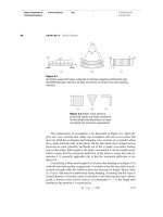
Let us now look in more detail to the structural components of a traditional railway bridge. Figure 1.19 shows the general layout of a doubletrack open-timber floor plate girder railway steel bridge. A train track of
this railway bridge consists of a pair of rails resting on timber sleepers.
For a single track, the sleepers are supported by two longitudinal steel
beams known as stringers. The stringers are spaced at specified distances
(a3), given by the national code of practice in the country of construction,
depending on the spacing between rails and the spacing between centerlines of trains (a2), in case of more than a single track. The stringers are
supported on cross steel beams known as cross girders. The cross girders
16
Ehab Ellobody
a2
S
Main plate girder
a
Cross girders
Sleepers
Upper wind bracing
a1
Rails
a3
S1
h
Stringers
Stringer
bracing
S1 Stiffeners
Cross
bracing
S2
S
Stiffeners
S2
L = n×a
Cross
bracing
Elevation
Stringer bracing
Stringers
B
Lower wind bracing
Main plate girder
Cross-section S-S
Cross girders
Main plate girder
Upper wind bracing
member
Cross bracing
L = n×a
Plan of upper wind bracing
(Section S1-S1)
Main plate girder
Cross bracing
Upper wind bracing
member
q
Bracing angle (30-60°)
Plan of upper wind bracing
(Section S2-S2)
Figure 1.19 General layout of a double-track open-timber floor plate girder railway
steel bridge.
are supported by two, in this case of bridges (Figure 1.19), longitudinal
main steel beams known as main plate girders, which are the main structural
system for this type of bridges. The main plate girders are supported on
supports called “bearings” such as the hinged and roller bearings shown in
Figure 1.19, which rest on foundations or piers, in case bridges are constructed over obstacles such as rivers, roads, and seas. The main girders
are spaced at a distance (B), which is the width of the bridge. The moving
Introduction
17
train loads are transmitted from the rails to the sleepers, from the sleepers to
the stringers, from the stringers to the cross girders, from the cross girders
to main plate girders, from the main plate girders to the bearings, from the
bearings to the foundations or piers, and finally from foundations or piers
to the ground. Wind and lateral loads acting on the bridge can be transmitted by systems of horizontal (upper and lower wind bracings) and vertical (cross
wind bracings) bracing systems, which carry out wind loads safely to the
bearings. Also, the stringers can be attached to horizontal systems of bracings called stringer bracing or lateral shock (nosing force) bracing, which transmit
lateral shock (nosing) forces resulting from the moving train safely to cross
girders where it causes additional small axial force on the cross girders. The
web of the main I-shaped plate girder bridge is very sensitive to buckling
since it has a thin thickness compared to its depth. Therefore, the web of
the plate girder is strengthened by vertical and horizontal stiffeners. The
spacing between the vertical stiffeners should be reasonably assumed
(1.5-2 m) not to increase the thickness of the web. Hence, the spacing
between cross girders (a) is dependent on the number of vertical stiffeners
used between two adjacent cross girders. Finally, the length of the bridge
(L) is equal to the number of (a).
The structural components of a traditional highway bridge can be
reviewed as shown in Figure 1.20. The figure shows the general layout of
a through truss highway steel bridge. The bridge has a RC floor supported
by a number of stringers. The stringers are spaced at designed distances (a3)
reasonably assumed between 2 and 3 m. Similar to railway bridges, the
stringers of this type of bridges are supported by cross girders. The cross
girders are supported by two longitudinal trusses, which are the main structural system for this type of bridges. The main trusses are supported on
hinged and roller bearings, which rest on foundations or piers. The truck
and car loads are transmitted from the RC floor to the stringers, from the
stringers to the cross girders, from the cross girders to the main trusses, from
the main trusses to the bearings, from the bearings to the foundations or
piers, and finally from the foundations or piers to the ground. Wind loads
acting on the bridge can be transmitted by systems of horizontal upper, since
this bridge is a through bridge with enough height to contain traffic in addition to overhead clearance, and end portal frames, since cross bracing
will close the bridges, which carry out wind loads safely to the bearings.
The bracing systems are also important to define the buckling lengths of
compression members of the main trusses. However, the stringers do not
need a bracing since the RC concrete floor takes care of any lateral and
18
Ehab Ellobody
S
Main truss
a
Upper wind bracing
S1
S1
Main truss
End portal
frame
h
S2
S2
Hinged bearing
L = n×a
S
Elevation
RC floor
a3
Cross girders
Lower wind bracing
Roller bearing
B
Stringers
Lower wind bracing
Cross-section S-S
Main truss
Bracing members
Plan of lower wind
bracing (Section S2-S2)
Cross girders
Main truss
Bracing members
End portal
frame
Plan of upper wind
bracing (Section S1-S1)
Figure 1.20 General layout of a through truss highway steel bridge.
longitudinal loads associated with moving traffic. Cross girders must be
aligned with vertical members to avoid adding bending moments to truss
members. Hence, the spacing between cross girders (a) is the spacing
between vertical truss members. The spacing between vertical truss members is dependent on the angle of inclined truss members, which is defined
by the height of the vertical members (h) that is dependent on the length of
the bridge (L). The length of the bridge (L) is equal to the number of spacing
between cross girders or vertical truss members (a).
Let us now look at the structural components and general layout of a
steel-concrete composite highway bridge shown in Figure 1.21. The bridge
has a RC floor supported by a number of main I-shaped plate girders.