Evaluation of methods for analyzing early-age cracking risk in concrete walls of tunnel structures
Bạn đang xem bản rút gọn của tài liệu. Xem và tải ngay bản đầy đủ của tài liệu tại đây (396.63 KB, 14 trang )
Transport and Communications Science Journal, Vol. 71, Issue 7 (09/2020), 746-759
Transport and Communications Science Journal
EVALUATION OF METHODS FOR ANALYZING EARLY-AGE
CRACKING RISK IN CONCRETE WALLS OF TUNNEL
STRUCTURES
Tu Anh Do1, Luan Minh Ha2, Quang Thac Nguyen3,
Tam Duc Tran4, Thang Quoc Tham1,*
1
University of Transport and Communications, No. 3 Cau Giay Street, Dong Da District,
Hanoi, Vietnam
2
Alstom Transport SA, 109 Tran Hung Dao Sstreet, Cua Nam, Hoan Kiem District, Hanoi,
Vietnam
3
Campus in Ho Chi Minh City, University of Transport and Communications, No. 450- 451
Le Van Viet Street, Tang Nhon Phu A Ward, District 9, Ho Chi Minh City, Vietnam
4
Hoa Binh Department of Transportation, No. 724, Cu Chinh Lan Street, Dong Tien, Hoa
Binh, Vietnam
ARTICLE INFO
TYPE: Research Article
Received: 15/6/2020
Revised: 11/9/2020
Accepted: 14/9/2020
Published online: 30/9/2020
/>*
Corresponding author
Email:
Abstract: This paper is concentrated on investigating the modern methods to evaluate the
probability of cracking in urban tunnel structures during construction. The study considers the
current standard methods for assessing reinforced concrete walls of an urban tunnel, which
experienced early-age cracking. The results obtained using guidelines were compared with
actual observations of crack widths in the urban tunnel wall. Examples of using specifications
in wall design were also described. The proper method is highlighted with suggestions for a
possible path for considering early-age thermal and shrinkage effects in urban reinforced
concrete tunnel walls.
Keywords: early-age concrete, early-age cracking, temperature, shrinkage, tunnel walls.
© 2020 University of Transport and Communications
746
Transport and Communications Science Journal, Vol. 71, Issue 7 (09/2020), 746-759
1. INTRODUCTION
Currently, in big cities, urban tunnel structures have been built to meet the increasing
traffic demand. However, there are many urban tunnels after construction, especially the
structure of the tunnel walls, which have detected many cracks, such as cracks in the open
tunnel walls of Thanh Xuan (Hanoi), Trung Hoa closed tunnel (Hanoi), etc. These initial
cracks may not directly damage the structure, however if they develop over time, they will
lead to detrimental influences on the structure such as decreases in concrete strength and
durability.
Some of the predictable objective reasons are those concrete structures that are affected
by heat and early-age shrinkage [1]. The early-age thermal-shrinkage effects prompt cracks
that can be observed in the first days after casting. This cracking is a big problem when the
crack width exceeds the critical value, which reduces the durability and usability of the
structure [2-8]. Moreover, after the end of concrete hardening, the cracking caused by volume
changes due to changes in temperature and moisture during the hardening process and may
also develop as a result of the temperature changes (daytime and seasonally), then concrete
continues to shrink and at the same time be subjected to mechanical loads. In addition, cracks
– even of insignificant width – may still lead to corrosion of reinforcement in the concrete [1].
These factors particularly affect structures such as bridge abutments’ walls and tunnels in
urban areas.
In countries around the world (such as the US, Japan, Europe, etc.), there have been
studies on cracking in concrete structures at the construction phase, as well as existing and
improving standards and regulations to control and ensure anti-cracking for construction
works. Currently, there are many standards used to evaluate cracks such as Eurocode 2 [9],
CIRIA C660 [10], JCI's Guidelines for control of cracking of mass concrete 2016 [11], the
standard of ACI committee 207.2R-07 [12].
In Vietnam, the construction standard TCXDVN 305:2004 [13] has also been applied to
the construction and acceptance of concrete structures and mass concrete. This standard only
gives two criteria: the temperature difference between the core and the surface of mass
concrete must not exceed 20oC and the module of the temperature difference between points
in mass concrete exceeds 50oC/m. However, in the hot and moist climate of Vietnam, the
effect of the environment on the temperature in early-age mass concrete (even during the
construction period) is significant. For example, there are urban tunnel construction projects
that must be constructed in the summer to ensure the construction schedule, with an ambient
temperature of up to 35-37oC. Besides, many other factors that affect the early-age cracking
of these structures that needs to be considered. Vietnamese standards do not specify particular
and appropriate methods for cracking identification and calculating crack width and crack
spacing.
Therefore, it is necessary to evaluate modern methods for analyzing risk of early-age
cracking in tunnel walls during construction phase in order to take measures to control and
prevent crack formation in such structures thus improving the durability and sustainability.
747
Transport and Communications Science Journal, Vol. 71, Issue 7 (09/2020), 746-759
2. REVIEW OF METHODS
2.1. Eurocode 2 [9, 14] and CIRIA C660 [10]
The British guidelines were published in 2007 as supplement to Eurocode 2 standards [9,
14], which describe early-age volume changes in the concrete to a limited extent. According
to the instructions provided in [10], the risk of cracking is assessed by comparing tensile
strains, r , induced in the wall structure after 3 days of concrete hardening with
corresponding ultimate strains, ctu . Therefore, the risk of cracking occurs when the following
condition is fulfilled:
r ctu
(1)
The tensile strain, r , in early-age concrete may be calculated from the following formula:
r = K1R(T T + ca + cd )
(2)
where:
T - the temperature difference, which in case of concrete walls with a predominant
contribution of restraint stresses [10, 15], is taken as the difference between the maximum
self-heating temperature and the ambient temperature after finishing the cooling phase. CIRIA
C660 includes diagrams enabling direct determination of the temperature difference, T , for
the wall depending on its thickness, the type and quantity of used cement, and the type of
formwork;
T - the coefficient of thermal expansion for concrete, dependent on the type of
aggregate;
cd - the strains due to drying shrinkage determined according to [9], the development
of drying shrinkage strain with time as follows:
cd (t ) = ds (t , ts ).kh . cd ,0
(3)
where:
cd ,0 - Nominal unrestrained drying shrinkage (in 0/00) [9].
kh - coefficient depending on the notional size h0,
t − ts
ds (t , ts ) =
(t − ts ) + 0.04 h 03
where:
t – the age of concrete at the moment considered, in days
ts – the age of concrete (days) at the beginning of drying shrinkage (or swelling).
Normally this is at the end of curing.
h0 – the notional size (mm) of the cross-section.
h0 = 2Ac/u. Where:
Ac – the concrete cross-sectional area
u – the perimeter of that part of the cross section which is exposed to drying
ca - the strains due to autogenous shrinkage determined according to [9];
748
(4)
Transport and Communications Science Journal, Vol. 71, Issue 7 (09/2020), 746-759
ca (t ) = as (t ). ca ()
(5)
where:
ca () = 2.5( fck − 10).10−6
(6)
as (t ) = 1 − exp(−0.2t 0.5 )
(7)
where t is given in days and fck is concrete compressive strength at the age of 28 days (MPa).
K1 - the coefficient of stress relaxation due to creep under sustained loading; the
recommended value is K1 = 0.65 or 1.0 when the R factor is taken based on [14].
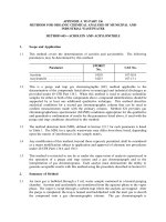
R- the restraint factor reflecting the degree of limiting deformation freedom. In the case
of walls cast on the existing foundation, R may be assumed according to [14] or based on
equations enclosed in ACI [12], which is described later. Values of the R factor corresponding
to the simplest case of a wall with limited deformation freedom along the lower edge are
visible in Figure 1.
Figure 1. The restrain factor R for a wall with limited deformation freedom along the lower edge [12].
Guidelines provide values of the ultimate strains, ctu , for concrete class C30/37 with
various types of aggregate (Table 1). When the concrete class differs from class C30/37, the
values given in Table 1 should be recalculated according to the formula:
ctu = ctuC 30/37 [0.63 + ( fck ,cube /100)]
(8)
where fck,cube is concrete compressive strength of cubic samples at the age of 28 days (MPa).
The thermal-shrinkage crack width in an element restrained along one edge may be
calculated according to the expression:
w = Sr ,max cr = [3.4c + 0.425
k1
p ,eff
] cr
(9)
where: c – is the cover to reinforcement (m),
- is the bar diameter (m),
cr - is given in Eq. (10),
k1 - a coefficient which take account of the bond properties of the reinforcement; [9]
749
Transport and Communications Science Journal, Vol. 71, Issue 7 (09/2020), 746-759
recommends 0.8 for high bond bars and 0.7 for standard bars, however [10] suggests the
higher value to be used for early-age thermal cracking, k1=0.8/0.7=1.14, due to the inability to
guarantee sufficient anchorage of reinforcing bars in the hardening concrete.
p ,eff - is the ratio between the area of reinforcement and the effective area of concrete,
A
calculated as p ,eff = s .
Ac ,eff
Ac ,eff - the effective area of concrete in tension around the horizontal reinforcement to a
B / 2
depth of hc ,eff , calculated from hc ,eff = min
, where B is the thickness of the
2.5(c + / 2
wall.
As - the area of horizontal reinforcement, m2.
Strain cr is lower than strain r due to the decrease in tensile force after cracking in the
wall:
cr = r − 0.5 ctu
(10)
Table 1. Ultimate strain, ctu , for concrete class C30/37 [10].
Coarse aggregate applied in
concrete1
ctu after 3 days
10
10-6
Basalt
63
90
Flint gravel
65
93
quartzite
76
109
granite
75
108
Lime stone
85
122
-6
ctu after 28 days
Sandstone
108
155
in case of no information about the applied type of aggregate, the
recommended value of ctu should be assumed as for quartzite
1
2.2. JCI guidelines for control of cracking of mass concrete 2016
The guidelines [11] developed by the Japan Concrete Institute (JCI) are the latest version
of Japanese standards concerning the design process and reducing cracking risk in mass
concrete structure. According to the current guidelines, numerical methods are recommended
for the design process and cracking risk assessment. Nevertheless, the simplified method has
also been provided in [11], resulting from comprehensive numerical simulations. In this
regard, the guidelines propose the special thermal cracking index for cracking risk
assessment, generally defined as a ratio between the tensile strength, ft(te), of concrete and the
generated principal tensile stresses, t(te):
I cr =
750
f t (te )
t (te )
(11)
Transport and Communications Science Journal, Vol. 71, Issue 7 (09/2020), 746-759
where te is the equivalent concrete age. If Icr ≥1:85, the probability of the cracking is 5%.
Otherwise, when Icr < 1:85, the probability of cracking P(Icr) may be estimated from:
I
P( I cr ) = 1 − exp − ( cr ) −4.29 .100
0.92
(12)
In detail, the thermal cracking index is given by:
I cr = (1 . 2 3 ) .I cr 0 − Ib
(13)
with the following coefficients:
α1 – considers the influence of the shape and stiffness of the structure and is calculated
1
1
H
1
from: 1 = a0 + a1 (
(14)
) + a2 (
) + a3 ln( ) + a4 (
)
E
D / D0
L / L0
H0
c / Er
Ec 0 / Er 0
α2 – considers the influence of the material and mix composition and is calculated from a
formula depending on the type of cement:
- For high early-age strength Portland cement:
(
Ta
)
2 = b0 + b1e T + b2e
a0
(−
Q 0
)
Q
+ b3e
(−
AT 0
)
AT
+ b4e
(
f 'c
)
f 'c 0
+ b5 (
S AT
)
S AT 0
(15)
- For other cements:
2 = b0 + b1e
(
Ta
)
Ta 0
+ b2 (−
f'
Q
S
) + b3 (− AT 0 ) + b4 ( c )0.45 + b5 ( AT )
Q 0
AT
f 'c 0
S AT 0
(16)
α3 – considers the influence of the curing method and is calculated from:
Tat +T
Tat
T
h
t
3 = c0 + c1 log e ( a ) + c2 ( ) + c3 ( ) + c4e
Ta 0
h0
t0
(17)
Additionally, the following coefficients are used in Eqs. (12) through (17):
, , , – coefficients representing the influence factor of each cement on the thermal
cracking index, coefficient values correspond to the type cement are provided in [11],
Icr0 – the basic thermal cracking index; the recommended value is Icr0 = 1.0,
Ib – the safety factor to ensure estimates comply with numerical results; the recommended
value for wall structures is Ib = 0.2,
a0–a4, b0–b5, c0–c4 – constants provided in [11], depending on the cement type,
D – the wall thickness; D0 – the reference value,
L – the wall length; L0 – the reference value,
751
Transport and Communications Science Journal, Vol. 71, Issue 7 (09/2020), 746-759
H – the wall height; H0 – the reference value,
Ec/Er – the ratio of the modulus of elasticity for the wall and the foundation; Ec0/Er0 – the
reference value,
Ta – the placing temperature, Ta0 – the reference value,
Tat – the ambient temperature, Tat – the reference value,
Q – the ultimate adiabatic temperature rise, Q 0 – the reference value,
AT , S AT – constants related to the temperature rise, AT 0 , S AT 0 – the reference values,
f’c – the concrete compressive strength, f’c0 – the reference value,
h – the heat transfer coefficient, h0 – the reference value,
t – the time until formwork removal, t0 – the reference value.
The applicable ranges of parameters listed above, as well as their reference values, are
generally determined by the type of cement and are given in corresponding tables or detailed
formulas found in [11]. The maximum thermal crack width is calculated based on the thermal
cracking index as follows:
w=(
−0.141
eff
+ 0.0938)( I cr − 1.965)
(18)
Where:
- a safety factor depending on the performance requirements and assumed from the
range 1–1.7;
eff - the degree of reinforcement in the horizontal direction; %
2.3. ACI Committee 207.2R-07 [12]
According to American guidelines ACI 231.R-10 [16], numerical methods are
recommended for the cracking risk assessment of early-age concrete. Nevertheless, former
guidelines ACI 207.2R- 07 [12] present an analytical method based on the comparison of the
tensile stresses, 𝜎(𝑡), with the actual value of the tensile strength of concrete, 𝑓𝑡(𝑡). Thus,
cracking occurs if the following condition is fulfilled:
(t ) ft (t )
(19)
The guidelines recommend controlling the above condition after 7 days of concrete
curing (t = 7 days). The tensile stress, (t), can be calculated from the following expression:
(t ) = K R K F (T T + cd ) Ecm,eff (t )
(20)
Generally, coefficients KR and KF reflect the degree of structure restraint. A change of
restraint at the height, H, of the wall with the limited deformation freedom along the bottom
752
Transport and Communications Science Journal, Vol. 71, Issue 7 (09/2020), 746-759
edge is considered by coefficient KR, which can be calculated based on the following
formulas:
- For L/H≥2.5
L/ H −2
KR =
L / H +1
y/ H
(21)
- For L/H<2.5
L / H −1
KR =
L / H + 10
y/ H
(22)
where y is the distance from the joint. For y=0, coefficient KR takes a maximum value of 1.0.
Coefficient KF refers to the degree of restraint in the contact layer between the restrained
and restraining members. Its value is dependent on the ratio between the corresponding values
of stiffness for these members:
KF =
1
A
1+ n C
AF
(23)
where:
AC - the cross-sectional area of the restrained member (wall), influenced by thermalshrinkage effects,
AF - the cross-sectional area of the member restraining the member influenced by
thermal-shrinkage effects (foundation),
N - the ratio between the modulus of elasticity for the concrete in the restrained element
(wall) and the modulus of elasticity for the concrete in the restraining element (foundation);
the recommended value is taken from the interval 0.6–0.8. Lower values correspond to longer
gaps between the casting of the restraining element (foundation) and the casting of the
restrained element (the wall).
The difference between the self-heating temperature and the external temperature is
calculated from the expression:
T = (Tpl + Tadiab ) − Tz
(24)
where:
Tpl - the initial temperature of the concrete,
Tadiab- the adiabatic temperature rise of the concrete,
Tz - the external temperature after 7 days from casting.
The adiabatic temperature rise, Tadiab, is estimated based on diagrams provided in [12].
753
Transport and Communications Science Journal, Vol. 71, Issue 7 (09/2020), 746-759
Reference [12] presents a simplified method for determining the drying shrinkage,
expressed by the equivalent temperature change:
TDS = (30 −
12V Wu − 125
)(
)
S
100
(25)
and the shrinkage strains:
cd = T TDS
(26)
Similar to the temperature determination, the units implemented in the formula (25)
hinder its application, i.e. Wu – the water content in the concrete mix, expressed in lb/yd3, V the volume of the member, in yd3, S - the area of the surface exposed to
drying, in yd2.
Generally, the guidelines recommend experimentally determining the modulus of
elasticity, Ecm (t); nevertheless, two formulas enabling analytical calculation of its value are
provided:
Ecm (t ) =
t
Ecm
a + bt
(27)
Where Ecm is the modulus of elasticity of concrete after 28 days, a=0.4, b=0.85, or:
Ecm (t ) = 0.043 1.5 fc (t )
(28)
where:
, the volume density of the concrete, kg/m3,
fc(t), the compressive strength of the concrete at age t
The compressive strength, fc(t), may be determined from the formula:
f c (t ) =
t
fc
a + bt
(29)
where fc is the compressive strength of concrete after 28 days, a=0.4, b=0.85.
Creep effects can be considered by using the effective modulus of elasticity, Ecmeff(t),
instead of the modulus of elasticity, Ecm (t) [17]:
Ecm,eff (t ) =
Ecm (t )
1 + (t , t ')
(30)
The creep coefficient (t , t ') for typical curing conditions is calculated according to:
(t , t ') = 2.35
(t − t ')0.6
10 + (t − t ')0.6
where t’ is the loading time
The tensile strength of concrete ft (t) may be determined from the following formulas:
754
(31)
Transport and Communications Science Journal, Vol. 71, Issue 7 (09/2020), 746-759
ft (t ) = 0.0069 f c (t )
0.5
ft (t ) =
t
ft
a + bt
(32)
where ft is the tensile strength of the concrete after 28 days, a=0.4, b=0.85.
Furthermore, the following formula is provided for determining the width of a thermalshrinkage crack, expressed in mm:
w = 0.00145 s 3 a1 Ac ,eff
(33)
where:
s - the stress in the reinforcement, MPa;
a1 - the distance from the surface to the center of gravity of the reinforcing bars, m;
Ac ,eff - the effective cross-sectional area of the member in tension, m2.
The average spacing between cracks is calculated from the expression:
sr =
w
K FT T − Ft (t ) / Ecm,eff
(34)
3. REAL WALL DATA AND COMPARISION BETWEEN METHODS
3.1. Examples of real wall
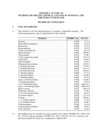
A real wall sample is taken from actual cracking survey data for the U6B segment of
open tunnel walls of Thanh Xuan (Hanoi) project. The plan view and the typical cracking
types are shown in Figures 2 and 3, respectively.
Figure 2. Cross- section and plan view of tunnel segment U6B.
755
Transport and Communications Science Journal, Vol. 71, Issue 7 (09/2020), 746-759
The properties of materials used for segment U6B are shown in Table 2.
Table 2. Material properties of real urban tunnel wall.
Material data
Concrete class
Cement type
Cement content
Water content
Aggregate type
Concrete density
28-day compressive strength fcm
28-day tensile strength fctm
Module of elastic Ecm
Horizontal reinforcement
Technological data
Ambient temperature
Initial concrete temperature
Dimensions
Basic dimensions
L/H
C25/30
CEM I 42.5 R
380 kg/m3
180 kg/m3
gravel
2400 kg/m3
33 MPa
2.6 MPa
31 GPa
6 14 / 0.9m at each surface
22.5oC
30.9oC
Fig. 3
4
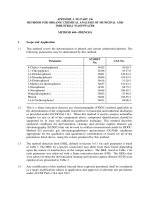
The actual cracking survey data is shown in Table 3 and Figure 3.
Figure 3. Side view - typical cracking types (units: mm).
Table 3. Actual cracking survey data for Segment U6B.
Segment Name of crack Length
Crack width
(m)
(mm)
U6B
9
2.00
0.15 0.5 0.2
10
4.00
0.15 0.25 0.25
11
1.60
0.10 0.10 0.1
12
2.00
0.20 0.20 0.2
13
2.00
0.15 0.25
14
2.00
0.30 0.30 0.15
756
Transport and Communications Science Journal, Vol. 71, Issue 7 (09/2020), 746-759
3.2. The results of calculation
The results obtained from the three procedures are presented in Tables 4 – 6, while Table
7 summarizes the results for comparison purposes.
Table 4. Evaluation of cracking risk
based on CIRIA C660.
Table 5. Evaluation of cracking risk
based on JCI.
Calculated value For example of
wall
39.80C
T
12x10-6
T
R
K1
ca
cd
r (h=0)
ctu
Cracking risk
cr (h=0)
k1
Concrete cover
c
As
0.3
1
44x10-6
523.575x10⁻⁶
1727.2x10-6
Icr
Cracking risk
P
eff
w
65x10-6
Yes
1694.73 x10-6
1.14
14 mm
60 mm
-4
83 x10 m
2
For example of wall
1.0
0.2
41.90C
1.193
0.755
1.120
0.8
1.4
0.5
0.3
0.99
yes
51.5%
0.63%
1-1.7
0.13-0.22 mm
0.1675 m2
Ac ,eff
p ,eff =
Calculated value
Icr0
Ib
Tadiab (T )
α1
α2
α3
As
Ac ,eff
4.96 %
Sr ,max
0.205 m
w
0.35 mm
Table 6. Evaluation of cracking risk based on ACI.
Calculated value
Tadiab
T
ΑT
KF
Ecm(t)
Ecm,eff(t)
t
For example of wall
33
38
12x10-6
0.91
26471MPa
16844 MPa
7 MPa
ft(t)
Cracking risk
w
Sr ,max
3 MPa
Yes
0.32 mm
0.85 m
757
Transport and Communications Science Journal, Vol. 71, Issue 7 (09/2020), 746-759
Table 7. Final comparison between CIRIA C660, JCI, and ACI methods.
Value
CIRIA C660 JCI
ACI Real value
T oC
39.8
41.9
38
No data
Cracking
Yes
Yes
Yes Yes
Cracking spacing, m 0.2
0.85 2.07
Crack width, mm
0.35
0.13-0.22 0.32 0.1-0.5
From the analysis results and the comparison (Table 7), it can be seen that the crack
widths calculated by CIRIA C660 and ACI are close. In addition, these two methods propose
calculation of cracking spacing while the JCI standard does not.
4. CONCLUSIONS
The clearest description of the early-age cracking assessment procedure for reinforced
concrete walls is CIRIA C660 among the 3 methods outlined in this paper. The procedure is
described thoroughly in the JCI guidelines but uses a number of coefficients making it
difficult to calculate. Additionally, the JCI procedure does not provide the computation of
spacing of potential cracks. The ACI method is difficult to use because of the imperial units
although it yields similar crack width compared with that using CIRIA C660.
The preliminary investigation in this paper shows that the calculation procedure proposed
by CIRIA C660 is the method that gives results close to the real wall cracking survey data and
is a very practical method for the design stage, which can reduce the workload and time. The
CIRIA C660 method needs further verifications on other tunnel walls’ cracking data before
final implementation can be included in the design process.
ACKNOWLEDGMENTS
This research is funded by the University of Transport and Communications (UTC) under
grant number T2020-CT-010.
REFERENCES
[1]. B. Klemczak, A. Zmij, Reliability of standard methods for evaluating the early-age cracking risk
of thermal-shrinkage origin in concrete walls, Construction and Building Materials, 226 (2019) 651661. />[2]. T. Do, H. Chen, G. Leon, T. Nguyen, A combined finite difference and finite element model for
temperature and stress predictions of cast-in-place cap beam on precast columns, Construction and
Building Materials, 217 (2019) 172-184. />[3]. T. Do, A. Lawrence, M. Tia, M. Bergin, Importance of insulation at the bottom of mass concrete
placed on soil with high groundwater, Transportation Research Record: Journal of the Transportation
Research Board, 2342 (2013) 113-120. />[4]. T. Do, A. Lawrence, M. Tia, M. Bergin, Determination of required insulation for preventing
early-age cracking in mass concrete footings, Transportation Research Record: Journal of the
Transportation Research Board, 2441 (2014) 91-97. />[5]. T. A. Do, Influence of footing dimensions on early-age temperature development and cracking in
concrete
footings,
Journal
of
Bridge
Engineering,
20
(2015)
06014007.
/>
758
Transport and Communications Science Journal, Vol. 71, Issue 7 (09/2020), 746-759
[6]. T. A. Do, T. T. Hoang, T. T. Bui, H. V. Hoang, T. D. Do, P. A. Nguyen, Evaluation of heat of
hydration, temperature evolution and thermal cracking risk in high-strength concrete at early ages,
Case Studies in Thermal Engineering, 21 (2020) 100658. />[7]. T. A. Do, A. M. Lawrence, M. Tia, M. J. Bergin, Effects of thermal conductivity of soil on
temperature development and cracking in mass concrete footings, Journal of Testing and Evaluation,
43 (2015) 1078-1090. />[8]. M. Tia, A. Lawrence, T. A. Do, D. Verdugo, S. Han, M. Almarshoud, B. Ferrante, A.
Markandeya, Maximum heat of mass concrete-phase 2, (2016). />[9]. EN, B., 1-1: 1992 Eurocode 2: Design of concrete structures, in General rules and rules for
buildings, 2008.
[10].P. Bamforth, Early-age thermal crack control in concrete, Vol. 660. 2007: Ciria London.
[11].Japan Concrete Institute, Guidelines for control of cracking of mass concrete 2016, 2017.
[12].ACI 207. Report on Thermal and Volume Change Effects on Cracking of Mass Concrete, 2007.
American Concrete Institute.
[13].TCXDVN 305:2004, Mass concrete - Code of practice of construction and acceptance 2004.
[14].EN, B., 3: 1992. Eurocode 2: Design of concrete structures-Part 3: Liquid retaining and
containment structures, in British Standards Institute, 2008.
[15].B. Klemczak, K. Flaga, A. Knoppik-Wrobel, Analytical model for evaluation of thermalshrinkage strains and stresses in RC wall-on-slab structures, Archives of Civil and Mechanical
Engineering, 17 (2017) 75-95. />[16].ACI, 231R–10 Report on Early-Age Cracking: Causes, Measurement and Mitigation, American
Concrete Institute, 2010.
[17].ACI, ACI 209.2 R-08: Guide for Modeling and Calculating Shrinkage and Creep in Hardened
Concrete, 2008.
759