Battery energy storage for enabling integration of
Bạn đang xem bản rút gọn của tài liệu. Xem và tải ngay bản đầy đủ của tài liệu tại đây (956.13 KB, 8 trang )
850
IEEE TRANSACTIONS ON SMART GRID, VOL. 3, NO. 2, JUNE 2012
Battery Energy Storage for Enabling Integration of
Distributed Solar Power Generation
Cody A. Hill, Member, IEEE, Matthew Clayton Such, Member, IEEE, Dongmei Chen, Member, IEEE,
Juan Gonzalez, Student Member, IEEE, and W. Mack Grady, Fellow, IEEE
Abstract—As solar photovoltaic power generation becomes
more commonplace, the inherent intermittency of the solar resource poses one of the great challenges to those who would
design and implement the next generation smart grid. Specifically,
grid-tied solar power generation is a distributed resource whose
output can change extremely rapidly, resulting in many issues
for the distribution system operator with a large quantity of
installed photovoltaic devices. Battery energy storage systems
are increasingly being used to help integrate solar power into the
grid. These systems are capable of absorbing and delivering both
real and reactive power with sub-second response times. With
these capabilities, battery energy storage systems can mitigate
such issues with solar power generation as ramp rate, frequency,
and voltage issues. Beyond these applications focusing on system
stability, energy storage control systems can also be integrated
with energy markets to make the solar resource more economical.
Providing a high-level introduction to this application area, this
paper presents an overview of the challenges of integrating solar
power to the electricity distribution system, a technical overview of
battery energy storage systems, and illustrates a variety of modes
of operation for battery energy storage systems in grid-tied solar
applications. The real-time control modes discussed include ramp
rate control, frequency droop response, power factor correction,
solar time-shifting, and output leveling.
Index Terms—Battery energy storage systems, photovoltaic, renewables, smart grid, solar.
I. INTRODUCTION
T
HE integration of significant amounts of photovoltaic
(PV) solar power generation to the electric grid poses a
unique set of challenges to utilities and system operators. Power
from grid-connected solar PV units is generated in quantities
from a few kilowatts to several MW, and is then pushed out to
power grids at the distribution level, where the systems were
often designed for 1-way power flow from the substation to the
customer. In climates with plentiful sunshine, the widespread
adoption of solar PV means distributed generation on a scale
Manuscript received November 22, 2010; revised June 20, 2011; accepted
January 18, 2012. Date of publication May 11, 2012; date of current version
May 21, 2012. This work was supported in part by Xtreme Power Systems,
Kyle, TX. Paper no. TSG-00256-2010.
C. A. Hill and J. Gonzalez are with the University of Texas, Austin, TX 78712
USA (e-mail: ; ).
M. C. Such is with Xtreme Power Systems, Kyle, TX 78640 USA (e-mail:
).
D. Chen is with the Department of Mechanical Engineering, University of
Texas, Austin, TX 78712 USA (e-mail: ).
W. M. Grady is with the Department of Electrical and Computer Engineering,
University of Texas, Austin, TX 78712 USA (e-mail: ).
Color versions of one or more of the figures in this paper are available online
at .
Digital Object Identifier 10.1109/TSG.2012.2190113
never before seen on the grid. The resulting challenges can
best be thought of as opportunities for both manufacturers and
utilities as they roll out various Smart Grid initiatives.
Grid-connected solar PV dramatically changes the load profile of an electric utility customer. The expected widespread
adoption of solar generation by customers on the distribution
system poses significant challenges to system operators both
in transient and steady state operation, from issues including
voltage swings, sudden weather-induced changes in generation,
and legacy protective devices designed with one-way power
flow in mind [1].
When there is plenty of sunshine during the day, local solar
generation can reduce the net demand on a distribution feeder,
possibly to the point that there is a net power outflow to the
grid. In addition, solar power is converted from dc to ac by
power electronic converters capable of delivering power to the
grid. Due to market inefficiencies, the typical solar generator
is often not financially rewarded for providing reactive power
support, so small inverters are often operated such that they produce only real power while operating a lagging power factor, effectively taking in or absorbing reactive power, and increasing
the required current on the feeder for a given amount of real
power. A radial distribution feeder with significant solar PV
generation has the potential to generate most of its own real
power during daylight hours, while drawing significant reactive
power. Utilities in the southwestern United States have started
to encounter power factor violations of the operating rules laid
down by the regional transmission organizations (RTO) and independent system operators (ISO) who have oversight over their
systems, and may incur fines for running their systems outside
of prescribed operating conditions. An example of such regulations is that set by the Electric Reliability Council of Texas
(ERCOT), which operates the electric grid and manages the
deregulated market for 75 percent of the state Texas. ERCOT
regulations require that distribution system operators (DSO) on
their system to maintain at least a 0.97 lagging power factor
for the maximum net active power supplied from a substation
transformer at its distribution voltage terminals to the distribution system [2].
Solar power’s inherent intermittency poses challenges in
terms of power quality and reliability. A weather event such
as a thunderstorm has the potential to reduce solar generation
from maximum output to negligible levels in a very short time.
Wide-area weather related output fluctuations can be strongly
correlated in a given geographical area, which means that the
set of solar PV generators on feeders down-line of the same
substation has the potential to drastically reduce its generation
in the face of a mid-day weather event. The resulting output
1949-3053/$31.00 © 2012 IEEE
HILL et al.: BATTERY ENERGY STORAGE FOR ENABLING INTEGRATION OF DISTRIBUTED SOLAR POWER GENERATION
851
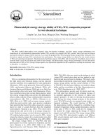
Fig. 1. Solar power measured over 24 hours at the La Ola solar installation at Lanai, Hawaii [5].
fluctuations can adversely affect the grid in the form of voltage
sags if steps are not taken to quickly counteract the change
in generation. In small power systems, frequency can also be
adversely affected by sudden changes in PV generation. Battery
energy storage systems (BESS), whether centrally located at
the substation or distributed along a feeder, can provide power
quickly in such scenarios to minimize customer interruptions
[3]. With the right control schemes, grid-scale BESS can
mitigate the above challenges while improving system reliability and improving the economics of the renewable resource,
thus providing a true smart grid solution to the integration of
distributed renewable energy sources to the 21st century grid.
This paper describes the operation and control methodologies
for a grid-scale BESS designed to mitigate the negative impacts
of PV integration, while improving overall power distribution
system efficiency and operation. The fundamentals of solar PV
integration and BESS technology are presented below, followed
by specific considerations in the control system design of solar
PV coupled BESS installations. The PV-coupled BESS systems
described in this paper utilize the XP-Dynamic Power Resource
(XP-DPR), a megawatt-scale integrated BESS developed for renewable energy applications, manufactured by Xtreme Power in
Kyle, TX. The system is currently operating in a solar-coupled
mode on 12.47 kV power systems in the Hawaiian Islands, at a
solar technology testing facility in Colorado under the auspices
of Xcel Energy and the National Renewable Energy Laboratory
(NREL), and at the high-power hardware-in-loop test facility at
Xtreme Power’s Kyle, TX headquarters, described in [4].
II. PHOTOVOLTAIC INTEGRATION
Modest levels of solar PV generation on distribution circuits
can be easily managed by the distribution system operator
(DSO). However, both the DSO and the customers of electric
retail service may soon feel the undesirable impacts on the grid
as PV penetration levels increase. The extent of the intermittency challenge is suggested by Fig. 1, depicting solar power
measured at a site in Hawaii on a normal spring day [5]. Solar
PV generation is becoming more economical every year, and
accommodating increased penetration levels is a central challenge for the next generation smart grid. In the United States,
increased solar PV generation capacity is being driven in part
by targets established under the auspices of the Renewables
Portfolio Standard (RPS), laws now on the books in a majority
of states that require utilities to source certain amounts of
generation from renewable resources like wind and solar power
[6]. Between RPS laws and improving economics, solar PV
generation is well positioned to become a significant source of
electricity in coming years. As solar PV generation penetration
increases, the electricity grid will increasingly be subjected to
sudden changes in generation and power flow at various points
on the system. A BESS can assist with orderly integration
of solar PV generation by managing or mitigating the less
desirable effects from high solar PV generation penetration.
As a cloud passes over solar collectors, power output from the
affected solar generation system drops. When the cloud moves
away from the collector, the output returns to previous levels.
Importantly, the rate of change of output from the solar generation plant can be quite rapid as solar PV systems have no inertia
in the form of rotating mass. The resulting ramping increases
the need for highly dispatchable and fast-responding generation
such as simple cycle combustion turbines to fill in when clouds
pass over the solar collector [6]. Solar irradiance and the resulting power output of PV can change by as much as 80% in
a matter of seconds due to the passing of a cloud. If the surface
area of the solar PV system is relatively small compared to the
cloud that is passing over it, the power output of the system will
be reduced significantly.
852
IEEE TRANSACTIONS ON SMART GRID, VOL. 3, NO. 2, JUNE 2012
Fig. 2. Simplified one-line diagram of a BESS in parallel with a Solar PV facility connected to the grid on a common bus.
Steady-state impacts of intermittency are often manifested
as voltage swings caused by the variability of electric current
flowing through the system impedance on the feeder to which
the PV is interconnected. These fluctuations in voltage can
have adverse interaction with switched shunt capacitor banks,
load tap changers, and line voltage regulators. The intermittent
output of the solar PV generation can cause an increase in
frequency of actuation of these devices, which reduces the life
expectancy of these components. Also, after a PV generation
change, the reactive power profile of the line is likely not to
be the most efficient possible in terms of line losses. For these
reasons, dispatchable energy storage can accommodate the
integration of large-scale solar generation and increase the operational efficiency across the entire electric power distribution
system.
III. BATTERY ENERGY STORAGE
A. Battery Energy Storage Basics
A grid-scale BESS consists of a battery bank, control system,
power electronics interface for ac-dc power conversion, protective circuitry, and a transformer to convert the BESS output
to the transmission or distribution system voltage level. The
one-line diagram of a simple BESS is shown in Fig. 2. Note
that a BESS is typically connected to the grid in parallel with
the source or loads it is providing benefits to, whereas traditional uninterruptible power supplies (UPS) are installed in series with their loads. The power conversion unit is typically a
bi-directional unit capable of four-quadrant operation, meaning
that both real and reactive power can be delivered or absorbed
independently according to the needs of the power system, up
to the rated apparent power of the converter.
The battery bank consists of many batteries connected in a
combination series-parallel configuration to provide the desired
power and energy capabilities for the application. Units are typically described with two numbers, the nameplate power given
in MW, and the maximum storage time given in MWh. The
BESS described in this paper is a 1.5/1 unit, meaning it stores
1 MWh of energy, and can charge or discharge at a maximum
power level of 1.5 MW. In renewable energy applications, it
is common to operate a BESS under what is known as partial
state of charge duty (PSOC) [8], a practice that keeps the batteries partially discharged at all times so that they are capable
of either absorbing from or discharging power onto the grid as
needed. Details of several recent BESS projects are given in [9]
and [10]. Grid connected lead-acid battery systems built in the
1980s and 1990s have demonstrated good longevity and reliability [11].
There are two main schools of thought regarding deployment of BESS technologies on the electric power distribution
system. One is to provide centralized storage at the MW level
at the distribution substation. The other camp would prefer to
see smaller energy storage systems distributed on the distribution feeders, networked together and remotely controlled at the
substation. Advantages to centralized storage include easy access to substation electrical and SCADA equipment, simplified
control schemes, economies of scale, and the fact that there is already utility-owned land available behind the substation fence.
The argument for small scale, also known as community energy
storage (CES) is made in [12] by engineers from American Electric Power. The ideal sizing and location will vary from site to
site. In the case of large solar PV installations, it typically makes
the most sense to install a comparably sized battery system tied
in to the grid at the same substation. This enables power quality
to be better maintained at the point of common connection, and
the renewable resource can be better dispatched. This paper focuses on MW scale batteries connected with multi-MW scale
PV facilities at the distribution substation.
Most BESS control systems can be operated via automatic
generation control (AGC) signals much like a conventional
utility generation asset, or it can be operated in a solar-coupled mode where real and reactive power commands for the
converter will be generated many times per second based on
real-time PV output and power system data. In the case of
the XP-DPR, three-phase measurements from potential and
current transducers (PTs and CTs) are taken in real-time on
an FPGA device, and once digitized these signals become the
input for proprietary real-time control algorithms operating at
kHz speeds. Various control algorithms have been used for PV
applications, providing control of ramp rates, frequency support, voltage/reactive power support, and services designed to
optimize the financial returns of the PV installation, including
peak-shifting and leveling.
B. Ramp Rate Control
As discussed above, solar PV generation facilities have no
inertial components, and the generated power can change very
quickly when the sun becomes obscured by passing cloud cover.
On small power systems with high penetrations of PV generation, this can cause serious problems with power delivery, as traditional thermal units struggle to maintain the balance of power
in the face of rapid changes. During solar-coupled operation,
the BESS must counteract quick changes in output power to ensure that the facility delivers ramp rates deemed acceptable to
the system operator. Allowable ramp rates are typically specified by the utility in kilowatts per minute (kW/min), and are a
common feature of new solar and wind power purchase agreements between utilities and independent power producers. Note
that the ramp rate refers only to real power, and that the reactive
power capabilities of the BESS can be dispatched simultaneously and independently to achieve other power system goals.
The Ramp Rate Control algorithm used in the XP-DPR continuously monitors the real power output of the solar generator,
and commands the unit to charge or discharge such that the total
HILL et al.: BATTERY ENERGY STORAGE FOR ENABLING INTEGRATION OF DISTRIBUTED SOLAR POWER GENERATION
853
Fig. 3. Ramp Rate control to 50 kW/min for a 1 MW photovoltaic installation and a 1.5 MW/1 MWh BESS. (a) Full day. (b) Detail of largest event.
power output to the system is within the boundaries defined by
the requirements of the utility. For more information on this algorithm, see [16].
Fig. 3 depicts the operation of an XP-DPR BESS smoothing
the volatile power output of a 1 MW solar farm. Note that the
system ramp rate is maintained to less than 50 kW/min, whereas
the solar resource alone had a maximum second-to-second ramp
rate of over 4 MW/min. This behavior translates to a significant
reduction in wear and tear on the diesel generators supplying
the rest of the grid, and helps the thermal units maintain power
balance and the system electrical frequency. It is typically the
case that the specifics of the thermal units on the system will be
a major factor in determining the allowable ramp-rates for the
PV asset. Ramp-rate control is often referred to as smoothing.
C. Frequency Response
Even with ramp-rate control, there are still going to be occasional frequency deviations on the system. On small, lowvoltage systems, it is not uncommon to see frequency deviations
of 1–3 Hz from the nominal 50 or 60 Hz frequency. Compare
this to power systems in the continental United States, where
many thousands of megawatts of generation are interconnected
and 0.1 Hz deviation is considered significant. Such frequency
deviation has adverse effects on many types of loads as well as
other generators. Frequency deviation is caused by a mismatch
in generation and load, as given by the swing equation for a
Thevenin equivalent power source driving the grid. The system
inertia is typically described using a normalized inertia constant
called the H constant, defined as
(1)
and H can be estimated by the frequency response of the system
after a step-change such as a unit or load trip. From the definition
of H in [13], the equation can be re-written so that the system H
is easily calculated from the change in frequency of the system
after a generator of known size has tripped off, according to
is the size of the generator that has
after the unit trip, and
tripped. Large, densely interconnected power systems have H
values of 6 seconds or higher, a value which can be interpreted
as how many seconds worth of energy is effectively stored as
mechanical inertia in the power system’s rotating machines. The
smaller the power system, the smaller the resulting H value,
and the more the frequency will be affected by a step change
in generation or load. Note that the H value discussed here is
for an entire power system, and that every individual generator
has its own H value as well.
When frequency crosses a certain threshold, it is desirable
to command the BESS to charge in the case of over-frequency
events, typically caused by loss of load, or to discharge for
under-frequency events, which often result when a generator has
tripped offline. Using proportional control to deliver or absorb
power in support of the grid frequency stabilization is referred
to as droop response, and this is common behavior in generator
governors equipped with a speed-droop or regulation characteristic. Droop response in a governor is characterized as a proportional controller with a gain of 1/R, with R defined as
(3)
where
is steady-state speed at no load,
is steady-state
speed at full load, and
is the nominal or rated speed of the
generator [14]. This means that a 5% droop response should
result in a 100% change in power output when frequency has
changed by 5%, or 3 Hz on a 60 Hz power system.
Since the BESS uses a power electronics interface, there is no
inertia or “speed” in the system, and we must approximate this
desirable behavior found in thermal generators. The straightforward implementation is to digitally calculate an offset for the
BESS output power command as response proportional to the
frequency. The response has units of kW and is determined as
(4)
(2)
where the unit of H is seconds, is system angular speed, is
the system frequency,
is the remaining generation online
where
band, and
is the grid frequency,
is the frequency deadis the power rating of the BESS in kVA.
854
IEEE TRANSACTIONS ON SMART GRID, VOL. 3, NO. 2, JUNE 2012
Fig. 4. Frequency droop response curves for 5% response on a 1 MW BESS.
As an example, setting the frequency deadband to 60.5 Hz
means that the BESS droop response would not engage until
there is a 0.5 Hz frequency deviation on the power system.
Implementing a droop response that discharges in the case
of under-frequency events is accomplished using the same
equation, with a deadband below nominal frequency, and a sign
change on Percent R. After the frequency has returned to the
normal range, the BESS can automatically return to ramp-rate
control. A set of droop characteristic curves for a 1 MW BESS
is depicted in Fig. 4. The separate lines show the resulting
power output of the BESS based on how much power it was
delivering or absorbing at the time the frequency event begins.
D. Reactive Support
In large interconnected power systems, system inertia and a
diversity of generation and loads make frequency control and
ramp rates a less significant concern for the distribution system
operator, but rapid power flow changes can still cause adverse
effects. In these cases, delivering reliable power to end-users
within a specified voltage range is the most important goal. An
important technical challenge for electric grid system operators
is to maintain necessary voltage levels with the required stability. A distribution feeder will typically employ a combination
of voltage regulators and switched or static shunt capacitors to
deliver power at a consistent voltage and power factor to all customers on the line. Power factor
is defined as
(5)
where P is the real power flow (in watts), S is the apparent power
flow (in volt-amperes or VA), and is the angle difference between the voltage and current waveforms on a given phase.
Power factor is continuously variable between 0 and 1, and can
be either leading or lagging. Lagging power factor indicates a
component that absorbs reactive power (in units of Vars), while
a leading power factor component is said to generate reactive
power. The natural inductance of overhead power lines, transformers, and many kinds of loads results in the absorption of
reactive power and a low, lagging power factor. The lower the
power factor, the more current must flow on the line to supply
a given power P as governed by the basic ac power equations.
Therefore, it is desirable to maintain a
near 1.0 in order to
minimize insulation requirements and as well as to minimize
and
losses, and to counteract voltage drop across the
system impedance.
On ac power distribution systems, voltage is a local phenomenon closely related to reactive power flows. Switched capacitors are often installed on the bus to provide reactive power and
regulate voltage. The capacitors are often switched in and out
of the circuit several times a day because reactive power needs
fluctuate according to load. The change in voltage from the insertion of a capacitor is approximated as
(6)
is the change in voltage,
is the rating of
where
the capacitor,
is the per-unit impedance of the upstream
step-down transformer, and
is the step-down transformer rating. This formula uses the step-down transformer
rating as an approximation of the local stiffness of the grid,
which is acceptable as the transformer typically provides the
majority contribution to the system total impedance at the
point of capacitor installation [15]. Shunt capacitor banks are
cheap and effective at providing reactive power support, but
have drawbacks in terms of large switching transients, and
the “all-or-nothing” nature of switching the bank in. Reactive
support with power electronics enables continuous changing of
the reactive power delivered into the system with no transients,
and this capability comes with no extra equipment necessary
once a BESS has been installed.
The four-quadrant power electronic converter on a BESS can
inject reactive power to the bus to maintain either a power factor
HILL et al.: BATTERY ENERGY STORAGE FOR ENABLING INTEGRATION OF DISTRIBUTED SOLAR POWER GENERATION
855
IV. METHODOLOGY
Fig. 5. Control architecture of the real-time HIL testbed at the Xtreme Power
facility in Kyle, TX.
Fig. 6. Power triangle used for the calculation of reactive power needed for
power factor correction.
or voltage setpoint on the bus, providing improved system efficiency, and lower losses. When maintaining a given power
factor, the power triangle can be used as depicted in Fig. 5. Applying trigonometry to the power triangle and substituting in (5),
we see that the necessary reactive power correction
to move
from an initial power factor of Q1 to Q2 is equal to
(7)
and Q can be readily adjusted to maintain the desired power
factor as the measured real power P at the bus changes.
Due to a market inefficiency that may be addressed with
time, the typical solar generator today is often not financially
rewarded for providing reactive power support, so solar inverters are often operated such that they produce real power
with no concern for reactive power contributions. The result is
poor power factor, which can be corrected by installing capacitors or power electronics devices. The benefits of improved
power factor can be quantified as reduced power system losses
, and reduction in line current
upline of
the reactive power source, whether capacitor or BESS. These
benefits are quantified according to
(8)
(9)
is power factor, and
where
from the power triangle [15].
is the power factor angle
There are two main types of distribution systems where BESS
are currently being used to help with high penetration PV. The
first is the common utility distribution feeder, which in North
America is typically a radial design, with all power originally
sourced from a transformer that steps down transmission voltages to 60 kV or less. Various solar installations in the 1 MW to
20 MW range have been connected to the grid at these substations, with significant impacts on the feeders downstream of the
substation. The other type is remote area power systems, where
small power systems are used that are not interconnected with
any of the major continental grids. These systems tend to experience significant frequency events and service interruptions
that are relatively more common. Additionally, the cost of fuel
in these remote locations is often very high, as it is typically
diesel fuel delivered by boat or plane. The economics of these
situations has made for favorable conditions for a BESS in such
locations as the Hawaiian Islands, islands and cities in Alaska,
and some parts of West Texas, to name a few.
The Xtreme Power facility in Kyle, TX is equipped with a
real-time Hardware-in-the-Loop (HIL) test-bed for BESS control systems, so that algorithms and control system components
can be adequately tested before deployment to the field. The
design of the HIL facility is discussed in [4]. Fig. 6 depicts the
functional parts of the HIL test platform, and indicates information flows between them.
The HIL facility can be operated with or without a 1.5 MW
BESS online. When operated without full hardware, software
simulations are used of the battery and power conversion
system, in a mode referred to as model-in-loop operation
(MIL). In the sections above, ramp-rate, droop response and
reactive power support operational modes have all been extensively tested in Kyle in both MIL and HIL test modes,
and the algorithms have been deployed to renewable energy
installations as part of an integrated 1.5 MW/1 MWh BESS and
control system solution. All results and graphs in this paper are
from testing in HIL mode at the Kyle facility.
V. MARKET ORIENTED OPERATION
In addition to using a BESS to help with the physical aspects
of integrating large quantities of solar such as ramp rates, frequency, and voltage regulation, a BESS can also be used to improve the economic profile of the distribution system to which
it is attached. To date, two of the main types of market-oriented
BESS operation that have been developed are time-shifting and
leveling. The specifics of the price structure of the energy markets that apply to a given distribution system operator vary considerably from place to place depending on the local market
rules and implementation. We present a general overview of
BESS market-oriented considerations, noting that the specifics
of each market are unique and must be considered independently.
Time-shifting is a well established practice with pumpedhydroelectric technology, a traditional form of energy storage.
Pumped hydro typically operates by pumping water to a higher
elevation at night when energy is cheap or there is extra capacity,
and letting the water flow back down through a hydroelectric
generator when energy is expensive. Using energy storage in
856
IEEE TRANSACTIONS ON SMART GRID, VOL. 3, NO. 2, JUNE 2012
Fig. 7. Full day output of the solar time-shift application.
Fig. 8. One hour of solar leveling application with 15-min output predictions and 10% tolerance on power bids.
this form transmits power across time in a way that is analogous
to what the electrical transmission system does across physical
space. A BESS used for a time-shifting application with PV is
often smaller than typical pumped hydro units, which are frequently sized in the hundreds of Megawatts range, and is more
likely to be connected at a distribution substation. This can provide various benefits from the perspective of the DSO, including
reduced demand from the transmission system step-down transformers when prices are highest.
Solar power generation is somewhat coincident with peak demand times, and PV connected BESS units can enhance this
characteristic by applying a time-shift algorithm optimized for
a given set of solar generation and load forecasts. By charging
from the grid at night, or from some percentage of the solar generation during the day, a BESS can be used to discharge as power
from the solar facility begins to drop off in the afternoon hours,
thereby offsetting the reduction in solar power at a time when
energy is expensive. This behavior is depicted in Fig. 7. Both
the peak extension duration period and the power output magnitude can be made user-configurable. The economic benefit of
the time-shift application is calculated by cost weighting the
integral of power delivered with the energy prices throughout
the day, and comparing the scenarios with and without solar
time-shift. Other benefits may include a reduction in congestion, line-losses, and pollution from inefficient “peaking” power
plants that are only operated at peak demand times.
In some energy markets the ability to schedule power generation ahead of time comes with significant economic benefits.
When this is the case, bidding the generation of 10 MWh over
some time period, and delivering it to within a specified accuracy can be worth much more than generating 10 MWh whenever the sun happens to be shining. In these situations, BESS
controls can be integrated with weather forecasts and market
signals to deliver power at a consistent output level. Control
logic on the BESS will use the battery to minimize deviations
between scheduled and actual power output throughout the day,
thus ensuring the maximum financial return on the day’s generation. Fig. 8 depicts results of a Solar Leveling application
using the Xtreme Power DPR at the Kyle test facility. Note that
the total power output from PV and BESS is maintained around
the power bid to within a user-specified tolerance of
.
Such behavior greatly improves the dispatchability of the PV
resource, and in many markets this will command a premium in
price compared to PV units without BESS support.
VI. CONCLUSION
Integration of energy storage systems into the smart grid to
manage the real power variability of solar by providing rate
variation control can optimize the benefits of solar PV. Using
the BESS to provide voltage stability through dynamic var
support, and frequency regulation via droop control response
reduces integration challenges associated solar PV. Coupling
solar PV and storage will drastically increase reliability of the
smart grid, enables more effective grid management, and creates a dispatchable power product from as-available resources.
The rapid-response characteristic of the BESS makes storage
especially valuable as a regulation resource and enables it to
compensate for the variability of solar PV generation. Battery
HILL et al.: BATTERY ENERGY STORAGE FOR ENABLING INTEGRATION OF DISTRIBUTED SOLAR POWER GENERATION
energy storage systems can also improve the economics of
distributed solar power generation by reduced need for cycle
traditional generation assets and increasing asset utilization of
existing utility generation by allowing the coupled PV solar and
BESS to provide frequency and voltage regulation services.
857
Cody A. Hill received the B.S. ECE degree from the University of Missouri,
Kansas City. He is currently a graduate student in electrical and computer engineering at the University of Texas at Austin.
He is a Power Systems/Controls Engineer for Xtreme Power in Kyle, TX,
and works primarily on the design of control systems for battery energy storage
systems in renewable energy applications.
REFERENCES
[1] F. Katiraei and J. R. Aguero, “Solar PV Integration Challenges,” IEEE
Power Energy Mag., vol. 9, no. 3, pp. 62–71, May/Jun. 2011.
[2] ERCOT Protocols Section 5 [Online]. Available: />Load%20Management_ERCOT_Emergency_Operation_Guidelines.pdf
[3] N. Miller, D. Manz, J. Roedel, P. Marken, and E. Kronbeck, “Utility
scale battery energy storage systems,” in Proc. IEEE Power Energy
Soc. Gen. Meeting, Minneapolis, MN, Jul. 2010.
[4] C. Hill and D. Chen, “Development of a real-time testing environment
for battery energy storage systems in renewable energy applications,”
in Proc. IEEE Power Energy Soc. Gen. Meeting, Detroit, MI, Jul. 2011.
[5] National Renewable Energy Laboratory—Measurement and Instrumentation Data Center [Online]. Available: />[6] J. Eyer and G. Corey, “Energy storage for the electricity grid,”
Sandia National Labs Publications, Feb. 2010 [Online]. Available:
/>[7] A. Nourai and C. Schafer, “Changing the electricity game,” IEEE
Power Energy Mag., vol. 7, no. 4, pp. 42–47, Jul./Aug. 2009.
[8] R. H. Newnham, W. G. A Baldsing, and A. Baldsing, “Advanced management strategies for remote-area power-supply systems,” J. Power
Sources, vol. 133, pp. 141–146, 2004.
[9] C. D. Parker and J. Garche, “Battery energy-storage systems for power
supply networks,” in Valve-Regulated Lead Acid Batteries, D. A. J.
Rand, P. T. Mosely, J. Garche, and C. D. Parker, Eds. , Amsterdam,
The Netherlands: Elsevier, 2004, pp. 295–326.
[10] N. W. Miller, R. S. Zrebiec, R. W. Delmerico, and G. Hunt, “Design
and commissioning of a 5 MVA, 2.5 MWh battery energy storage,” in
Proc. 1996 IEEE Power Eng. Soc. Transm. Distrib. Conf., pp. 339–345.
[11] “Analysis of a valve-regulated lead-acid battery operating in utility energy storage system for more than a decade,” 2009.
[12] A. Nourai, R. Sastry, and T. Walker, “A vision & strategy for deployment of energy storage in electric utilities,” in Proc. IEEE Power Energy Soc. Gen. Meet., Minneapolis, MN, Jul. 2010.
[13] J. D. Glover, M. S. Sarma, and T. J. Overbye, Power System Analysis
and Design. Stamford, CT: Cengage, 2008, p. 698.
[14] P. Kundur, Power System Stability and Control. New York: McGraw-Hill, 1994, pp. 589–594.
[15] R. C. Dugan, M. F. McGranaghan, S. Santoso, and H. W. Beaty,
Electrical Power Systems Quality. New York: McGraw-Hill, 2002,
p. 295.
[16] “Managing Renewable Power Generation, Xtreme Power,” U.S. Patent
20110273129, 2011.
Matthew Clayton Such received a B.S. ECE degree from the University of
Texas at Austin. He is currently a part-time graduate student in mechanical engineering at the University of Texas at Austin.
He is a Principal Engineer at Xtreme Power Systems, Kyle,. TX. He is responsible for design, validation, and maintenance of controls systems in XP
products, specifically the large scale storage products. Primary is focus on control and systems functions improvements and development.
Dongmei Chen received the B.S. degree from Tsinghua University, Beijing,
China, and the M.S. and Ph.D. degrees, both in mechanical engineering, from
the University of Michigan, Ann Arbor, in 2001 and 2006, respectively.
She is currently an Assistant Professor in the Department of Mechanical Engineering at the University of Texas at Austin. Her research interests are in dynamic systems and controls, especially in non-minimum phase, multivariable,
and mode switching systems, with applications in wind and solar energy integration, energy storage, and electrical vehicles.
Dr. Chen was a recipient of the University of Michigan Rackham Graduate
School Fellowship from 2000 to 2005. She received several awards for technical
excellence while working in the automotive industry.
Juan Gonzalez received the B.S. ECE degree from Simon Bolivar University,
Venezuela, and the M.S. ECE degree from the University of Texas at Austin.
He is a Power Systems Engineer for Xtreme Power in Kyle, TX, where he
currently is involved in the design and interconnection of battery storage systems in renewable energy applications.
W. Mack Grady (F’00) received the B.S.E.E. degree from the University of
Texas at Arlington in 1971, and the M.S.E.E. and Ph.D. degrees from Purdue
University, West Lafayette, IN, in 1973 and 1983, respectively.
He is a Professor and the Associate Chairman of Electrical & Computer Engineering at the University of Texas at Austin. He is the Jack S. Josey Centennial
Professor in Energy Resources at the Cockrell School of Engineering.
Dr. Grady is a Registered Professional Engineer in Texas. He holds a security clearance and works on power grid and power distribution issues for the
Scientific Applications and Research Associates (SARA) team on Department
of Defense (DOD) Defense Threat Reduction Agency projects.