Hưỡng dẫn động cơ ba pha
Bạn đang xem bản rút gọn của tài liệu. Xem và tải ngay bản đầy đủ của tài liệu tại đây (931.52 KB, 47 trang )
INSTRUCTIONS
FOR
THREE PHASE
INDUCTION MOTORS
TECO Electric & Machinery Co., Ltd.
1
INDEX
1. INTRODUCTION…………………………………………………………………………………….2
2. ACCEPTING, INSPECTION, STORAGE, TRANSPORTATION………………………….…….3
2.1 Inspection upon receipt.…………………………….………….……………………………….3
2.2 Storage.…………………………………………………………………………………………..3
2.3 Transportation.……………………………………..………………………………….…………6
3. INSTALLATION……………………………………………………………………….……………...7
3.1 Site and environment for motor installation…………………………………………………..7
3.2 Foundation……………………………………………………………………………………….7
3.3 Installation of shaft coupling………………………………………………….………………...9
3.4 Installation for belt drive……………………………………………………………………….13
3.5 Conveyance with chain or gear……………………………………………………………....15
3.6 Electrical connections………………………………………...…………………………….…15
4. OPERATION………………………………………………………………………………...……...17
4.1 Examination before start………………………………..……………………………………..17
4.2 Starting operation……………………………………………………………………………...21
5. MAINTENANCE……………………………………………………………….……………………24
5.1 Major points in regular inspection and maintenance……………………………….………24
5.2 Motor windings………………………………………………………………………………....25
5.3 Clean the interior of the motor………………………………………………………………..25
5.4 Clean the exterior of the motor……………………………………………………………….26
5.5 Maintenance of anti-friction bearing………………………………………………………….26
5.5.1 Frequency of relubrication……………………………………………………….………26
5.5.2 Kinds of grease……………………………………….…………………………………..28
5.5.3 Grease quantity…………………………………………………………………………..28
5.5.4 Re-greasing…………………………………………………………………………….…29
5.5.5 Oil relubrication……………………………………………………………………...……29
5.5.6 Cleaning and installation of bearings………………………………………………..…30
5.6 Maintenance of sleeve bearing…………………….………………………………….……..31
5.6.1 Daily inspections……………………………………………….…………….….………31
5.6.2 Regular examination…………………………………………………………….……….31
5.6.3 Disassembly……………………….……………………………………………...………32
5.6.4 Reassembly…..……………………………………..……………………………………34
5.7 Maintenance of slip ring (for Wound Rotor only)……………………………………………35
5.8 Maintenance of non-reverse ratchet mechanism…………………………………………..37
6. FAULT FINDING AND RECOGNITION……….…………………………………………………39
7. TECO Worldwide Operations…………………………………………………………………….41
Page
2
1. INTRODUCTION
This and the following instructions address the more common situations encountered in motor
installation, operation and maintenance. For the TECO motor warranty to be and to remain in effect,
the motor must be installed and operated in strict accordance with the outline drawing, motor
nameplates and these instructions and must not be altered or modified in any unauthorized manner.
During these installations and operation of motors in heavy industrial applications there is a danger
of live electrical parts and rotating parts. Therefore to prevent injury and/or damage the basic
planning work for installation, transport, assembly, operation, etc.… needs to be done and checked
by authorized and competent personnel only.
Since these instructions cannot cover every eventuality of installation, operation and maintenance,
the following points should however be considered and checked.
● The technical data and information on permissible use such as assembly, connection, ambient and
operating conditions given in the related catalogue, operating instructions, nameplates and other
production documentation.
● The general erection and safety regulations.
● The local and plant-specific specifications and requirements.
● The proper use of transport, lifting devices and tools.
● The use of personal protective equipment.
Following indications should be observed when reading these instructions.
Safety instructions are marked as follows:
Warning of electric hazards for personnel.
Warning of dangers for personnel.
ATTENTION!
Warning of damage for the motor or installation.
3
2. ACCEPTING, INSPECTION, STORAGE, TRANSPORTATION
2.1 Inspection upon receipt
Check the following points upon receipt:
● Are the nameplate ratings identical with what you ordered?
● Are dimensions and color in compliance with your specifications?
● Are the nameplate ratings for heater, thermal protector, temperature detector, etc. identical with
what you ordered?
● Is there any damage?
● Are all accessories and accompanying instruction manuals in good order?
● Please ensure that the arrowhead indicator really indicates direction of revolution.
● If there are any specific requirements, please ensure they are in conformity with your
specification.
2.2 Storage
When motors are not in operation, the following precautionary measures should be undertaken to
assure best performance.
2.2.1 Place
(a) High and dry, well-ventilated without direct sun, dust or corrosive gas.
(b) Not located near to a boiler or freezer.
(c) Entirely free from vibration and easy for movements.
(d) Motors should be put on pallets to prevent moisture.
2.2.2 Well protection
Motors should be well shielded from dust, but under well-ventilated circumstances. For those
water-cooling motors or using bearings with water-cooling coils, please make sure the water already
dried off to prevent tube corrosion or danger of frost.
2.2.3 Moisture prevention
Since moisture can be very detrimental to electrical components, the motor temperature should be
maintained about 3℃ above the dew point temperature by providing either external or internal heat.
If the motor is equipped with space heaters, they should be energized at the voltage shown by the
space heater nameplate attached to the motor. Incandescent light bulbs can be placed within the
motor to provide heat. However, if used, they must not be allowed to come in contact with any parts
of the motor because of the concentrated hot spot that could result.
2.2.4 Insulation resistance test
Even during storage, the insulation resistance should be kept above the specified values.
(a) For measurement of insulation resistance and acceptable standard values, please refer to
measures stated in 4.1.2 "Measurement of insulation resistance".
(b) Insulation resistance test should be performed once every three months.
4
2.2.5 Long period storage
If the motor is not in operation for a long period (one week and above) after installation or has been
in operation but stopped for a period of time, the following precautions must be taken.
(a) Protect the motor as measures stated in 2.2.3.
(b) Insulation resistance test should be performed as stated in 2.2.4.
(c) Bearing protection per 2.2.6.
(d) Operation test should be performed once every three months.
(e) Storage maintenance is to be documented for warranty data.
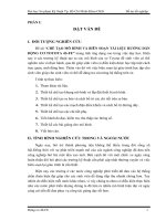
2.2.6 Bearing protection
(a) If the motor has been provided with a shaft shipping brace to prevent shaft movement during
transit, it must be removed before operating the motor.
It is very important that this brace be reinstalled exactly as it was originally, before the motor is
moved from storage or any time when the motor is being transported. This prevents axial rotor
movement that might damage the bearings.
Fig. 1
(b) Motors equipped with sleeve bearings are shipped from the factory with the bearing oil
reservoirs drained. In storage, the oil reservoirs should be properly filled to the center of the oil
level gauge with a good grade of rust inhibiting oil. To keep the bearing journals well oiled and
to prevent rusting, the motor shaft should be rotated several revolutions about every month
ensuring the shaft does not come to rest in its original position. While the shaft is rotating, it
should be pushed to both extremes of the endplay. If the motor is not in operation over six
months, dismount the upper cover of sleeve bearing housing and check the anti-corrosion
protection.
(c) Motors with anti-friction bearings are properly lubricated with the correct grade of grease at the
factory and no further greasing is required in storage. If the motor is not in operation over three
months, add grease to each bearing per lubrication nameplate. The shaft should be rotated
several revolutions about every month to maintain proper distribution of the grease within the
bearings.
(d) Tilt-pad bearings are a type of sleeve bearing used in special design applications. Due to the
nature of this bearing, a loose oil ring for delivering lubricant cannot be provided. Therefore,
during the storage interval, oil must be periodically manually introduced into the pads and
housing to prevent the occurrence of oxidation of the precision machined components.
Shaft Shipping
Brace
5
(1) Remove the pipe plug from the bearing cap located above the tilt-bearing shell.
(2) Pour in approximately one cup of oil every month and rotate the shaft a few revolutions
about every two (2) weeks.
For long periods of storage, the oil that accumulates in the housing should be removed.
(e) The bearing assembly parts of motors with oil mist lubrication are put on with anti-rust oil, so
they can be preserved for several months in good conditions. The motor should be stored indoor
& well-ventilated environment and prevent to contact with contaminated or corrosive air. The
following points should be noted:
(1) During preservation, the Inpro seal can not prevent the moisture to go through into the
bearings. Please use the oil mist to lubricate the bearings every two (2) weeks.
(2) If the color of flow out oil is changed, the bearing should be rusted or having contamination
in it. Please contact with us.
(3) Avoid using grease as it will plug the vent/drain.
(4) All assembly surfaces are painted with seal bonds, don't disassemble them anytime.
(5) Don't remove the plugs in vent/drain to prevent the moisture.
(6) Don't apply any force on the Inpro seal to prevent damage.
(7) The Inpro seal is a labyrinth type seal. Therefore it can not contain a pressure differential.
2.2.7 Prevent rusting
ATTENTION!
Cares should be taken to keep parts such as fitting surface, key, shaft extension and axial
central hole from any collision with foreign matters. Grease should also be generously
applied to prevent rusting.
6
2.3 Transportation
Do not use the hoisting hook/eyebolts to lift more that the motor itself. They are
designed to support the motor only.
Make sure the hoisting hook is correctly attached to the eyebolt(s) or lug(s) of the
motor and that the eyebolt(s)/lug(s) are fully screwed in before hoisting. Also note
such parts as fan cover, ventilation box, bracket, slip-ring, etc. may have their own
hoisting lugs which can only carry their own weight. Nothing extra should be
attached while hoisting.
Do not twist the steel wires and make sure the eyebolts have been firmly screwed and
the sling angle is correct.
Fig. 2
ATTENTION!
To keep the rotating parts of motors from moving, thus preventing damage and scratching
during transportation, they should be held securely with a locking device. Remove all
transit clamps before operating the motor. It is very important that this device be
reinstalled exactly as it was originally, before the motor is moved from storage or any time
when the motor is being transported.
The vertical mounting type motors should be transported in the vertical position.
Suspension Rod
Suspension Rod
7
3. INSTALLATION
3.1 Site and environment for motor installation
3.1.1
Standard environment and site conditions for the installation of motors are usually set as follows:
(a) Ambient temperature:-20 ~ +40 ℃
(b) Humidity:Relative humidity below 95%RH for totally-enclosed types, and below 80%RH for
semi-enclosed types.
(c) Elevation:below 1000 meters.
(d) Harmful gases, liquids, dusts, high moisture should be absent.
(e) Foundations should be strong and free of vibration.
For those water-cooling motors or using bearings with water-cooling coils, the ambient temperature
shall not below 0℃ to prevent danger of frost. If there are any special environmental conditions,
please inform us upon ordering.
3.1.2 Ventilation and space
(a) Installation area should be well-ventilated.
(b) The installation space should be large enough to facilitate heat dissipation and maintenance.
3.2 Foundation
3.2.1 Soleplate & common bed
Use rigid and solid soleplate or common bed as foundation.
Fig. 3
ATTENTION!
For best motor performance, it is advisable to use a soleplate or common bed, particularly
when using a shaft coupling.
If the soleplate or common bed does't have enough stiffness, the critical speed of motors or
equipment will then be changed. This change may cause a large vibration (resonance) and
decrease the life of machines.
Bearing
Stand
Motor
Bearing
Stand
Coupling
Load machine
Motor
Coupling
Load
Machine
Common
Bed
Common
Bed
8
3.2.2 Installation
(a) Select an appropriate foundation surface for the soleplate or common bed which will be
considered the ultimate level.
(b) Align the position of the common bed with reference to that level.
(c) Align the level accuracy at least at four points such as bearing mounting, shaft extension etc.
The accuracy should be within 0.04mm (1.5mil).
(d) Soleplate or common bed should be embedded in concrete foundation as illustrated in Fig.4.
Stiff pads should also be installed beneath the wedges which are welded together at various
spots about 400-500mm (15-20inches) apart etc., to enable foundation to carry evenly the
weight of the whole motor.
(e) The base should be sturdy and rigid to keep it flat and level.
(f) Make sure the mortar and concrete are
completely dry, and the precision of the
level is acceptable, then set the motor on
the mounting foundation.
(g) Accurately install shaft couplings, belt
sheaves etc., then weld the wedges solid
to prevent untoward change in position.
3.2.3 The foundation of vertical induction motor (Also the foundation of pump)
(a) Foundation of motor/pump must be rigid and secure to provide adequate support. There must be
no vibration, twisting, misalignment etc. due to inadequate foundations.
(b) A massive concrete foundation is preferred in order to minimize
vibration. Rigidity and stability are enhanced by prop plate and
foundation bolt. As shown in Fig.5 and Fig.6.
Fig. 4
Discontractive
mortar
Wedge
Pad
Concrete
Foundation
Welding
Spots
Mortar
Hex nut
Foundation bolt
Prop plate
(SS41)
Base plate
Concrete
Fig. 6
Fig. 5
Motor
Motor support
Base foundation
Pump
Fig. 5
9
3.2.4 Installation of vertical motor
(a) All mounting surfaces must be clean and level.
(b) Foundation must be leveled at least at 4 points and guaranteed to be below 0.04mm flat and
level.
(c) Make sure the mortar and concrete are completely dry, and the precision of the level is
acceptable, then set the motor on the mounting foundation.
(d) Accurately install shaft couplings.
3.3 Installation of shaft coupling
3.3.1 General
3.3.2 Mounting procedure
Field application of a coupling to the motor shaft should follow the procedures recommended by the
coupling manufacturer. The motor shaft extension must not be subjected to either extreme heat or
cold during coupling installation.
3.3.3 Safety attention
3.3.4 End-play
Although the sleeve bearings are equipped with thrust faces, these are intended only to provide
momentary axial restraint of rotor movement either during start-up or when operating the motor
disconnected from the driven equipment. They must not be operated under a constant thrust load
unless they were originally designed for this condition.
Motors with either sleeve or anti-friction bearings are suitable for connection to the driven load
through a flexible coupling. Coupling solidly to the load is not acceptable. With sleeve bearings, the
flexible coupling should be of the limited end float type to prevent the possibility of any end thrust
from the load being transmitted to the motor bearings, which could cause bearing damage.
The recommended limits of end float for couplings are as follows:
ATTENTION!
Motors must always be accurately aligned, and this applies especially where they are
directly coupled.
Incorrect alignment can lead to bearing failure, vibration and even shaft fracture. As soon
as bearing failure or vibration is detected, the alignment should be checked.
ATTENTION!
Basically, the coupling should be heated and pushed onto the shaft extension with slight
axial force. Do not hammer coupling to prevent bearing damage.
10
(a) When the motor is in operation after installation, be sure that the end-play indicator is within the
6mm of the groove on the shaft or aligned to the shaft shoulder immediately outboard of the
drive-end bearing to assure there is low friction between shaft and bearing.
(b) Unless otherwise specified, the designed end-play value X of the groove for TECO motors in
general is within 7mm (0.276”) as illustrated in Fig. 7. In essence, the end-play indicator is
adjusted to point at the center of the groove or the drive-end shaft shoulder; thus X equals to 7±
1mm (0.276”±0.039”) or so, and the end-play value (Y) of the couplings should equal or be
smaller than 2.4mm (0.094”).
(c) If the desired value Y is greater than 3mm (0.118”) caused for instance by a thrust load and/or
load machine with large end-play, please inform us when ordering.
3.3.5 Thermal growth
In aligning the motor (and rotor) axially with the driven equipment, consideration should be given
not only to the end-play indicator position but also to axial shaft expansion and increase in shaft
centerline height due to thermal effects. In general, the axial shaft growth for motors can be
disregarded since neither bearing is fixed and any shaft growth due to temperature increase will
produce an elongation away from the coupling.
Shaft height growth (change in shaft centerline elevation) for TEFC machines can be calculated as
follows:
Δ=(0.0005)×(motor foot to shaft centerline dimension)
For non-TEFC machines, divide this number by 2.
3.3.6 Alignment
It is desirable, in normal operation, that the motor operate on its magnetic center, so that no axial
force is exerted on the coupling.
The motor shaft and the driven shaft should be aligned within the following tolerances in both
angular and parallel alignment:
Fig. 7
X
1
≧7mm (0.276”) X=7mm (0.276”)
End-play indicator
Y≦2.4mm
The value of the
groove is 6mm
(0.094”)
(0.236”)
11
Unit:mm
TIR Range of rotating speed Solid coupling Flexible coupling
2500rpm and above 0.03 0.03 C
Below 2500rpm 0.04 0.05
2500rpm and above 0.03 0.03 A
Below 2500rpm 0.03 0.04
Angular misalignment is the amount by which the centerlines of driver and driven shaft are
skewed. It can be measured using a dial indicator set up as shown in Fig.8. The couplings are
rotated together through 360 degrees so that the indicator does not measure run out of the coupling
hub face. The shafts should be forced against either the in or out extreme of their end float while
being rotated.
Fig. 8 Fig. 9
Parallel misalignment is the amount by which the centerlines of the driver and driven shafts are
out of parallel. It can be measured using a dial indicator set up as shown in Fig.9. Again, the
couplings are rotated together through 360 degrees so that the indicator does not measure runout of
the coupling hub outside diameter.
TIR = Total indicator reading (by dial indicator)
3.3.7 Dowel
After the motor has been properly aligned with the driven equipment and the hold-down bolts have
been installed and tightened, for motors with fabricated frame, at least two dowel pins should be
installed in two diagonally opposite motor feet.
3.3.8 Installation of shaft coupling (Vertical hollow shaft motor only)
Bolted coupling as Fig.10
(a) Bearings are provided to absorb some upward shaft thrust when the coupling is fitted.
(b) The coupling is fastened with bolts.
(c) This coupling type is not auto-release type.
Note:Standard high thrust motors can absorb momentary upthrust load up to 30% of the standard
downthrust load. If the upthrust is long duration (over 10 seconds) and/or exceeds 30% of
the standard high thrust rating, special design arrangements are required and a standard
motor is not suitable.
“A” TIR
indicato
r
Indicator
base
Coupling Hubs
“C” TIR
indicator
Indicator
base
Coupling Hubs
12
3.3.9 Non-reverse ratchet/coupling, as Fig.9 (If necessary)
The non-reverse coupling is also a bolted type and,
(a) It prevents the pump and motor from rotating in the reverse direction.
(b) It also prevents damage from over speeding and damage to pump shaft and bearings.
(c) The ratchet pins are lifted by the ratchet teeth and are held clear by centrifugal force and friction
as the motor comes up to speed.
(d) When power is removed, speed decreases, and the pins fall. At the instant of reversal, a pin will
catch in a ratchet tooth and prevent backward rotation.
(e) When installing the non-reverse coupling, do not use lubricant. Lubrication will interfere with
proper operation. The top half of the coupling should seat solidly on the lower half and the pins
should touch the bottom of the pockets between the teeth in the plate.
(f) As with the bolted coupling, the upthrust capabilities are 30% of the standard high thrust rating
for downthrust.
3.3.10 Removal of redundant shaft key
When the length of coupling hub is different from the length of shaft key, the motor may have a
high vibration level due to this unbalance condition. The removal of redundant shaft key is
necessary, shown as Fig.11.
ATTENTION!
Do not apply non-reverse ratchets on applications in which the pump reversal time from
shutdown (the instant the stop button is pressed) to zero speed is less than one second.
Fig. 10
Upthrust
bolt
Pump
shaft
Drive
coupling
Drive
pin
Ratchet pin
13
Method (1):
After installing the coupling, use a
grinding wheel to remove the redundant
key (hatch area).
Method (2):
Before installing the coupling, calculate
the different length between coupling hub
and shaft key, then cut the half of this
different value (hatch area) to achieve
approximate-balance condition.
Method (2) Method (1)
3.4 Installation for belt drive
In general, power transmission through direct flexible coupling is appropriate for large motors.
Such motors are not suitable for belt, chain or gear connection unless specially designed for such
service. However, for small and medium motors of which outputs within the ranges shown on table
below, it is acceptable to use belt transmission as indicated. Beyond these ranges, do not apply belt
sheaves unless specially designed.
3.4.1 Diameter of sheaves
The diameter ratio between conveyance sheaves should not be greater than 5 to 1 for flat belts, and
8 to 1 for V-belt. It is also advisable to limit the belt velocity to under 35 m/sec to limit belt abrasion
and vibration. The smaller the outer diameter of the V-belt sheave, the greater the shaft bending
stress will be. If the bending stress is in excess of the shaft fatigue stress, the shaft may break.
Therefore, please inform us when you have decided the size of the sheaves and the length of the
belts upon ordering.
ATTENTION!
Place the sheave and belt as close as possible to the motor body
(it is advisable to make x as shown in Fig.12 equal to 0) to
reduce the bending moment and improve shaft life.
Fig. 11
Fig. 12
Redundant
key
Coupling
Redundant
key
Coupling
Drive-end
shaft
Drive-end
shaft
V-belt
sheave
Drive-end
shaft
14
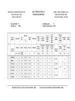
3.4.2 Table of belt-sheave application for general electric motors
V-Belt Sheave Output
(kW)
Conventional V-Belt Narrow V-Belt
4P 6P 8P
V-Belt
Type
Number
of
Belts
Min.
PCD
(mm)
Max.
Width
(mm)
V-Belt
Type
Number
of
Belts
Min.
PCD
(mm)
Max.
Width
(mm)
11 -- -- B 4 160 82 3V 4 125 48
-- 11 -- B 5 170 101 3V 5 140 59
-- -- 11 B 5 190 101 3V 6 160 69
15 -- -- B 5 170 101 3V 6 125 69
-- 15 -- B 5 224 101 3V 6 160 69
-- -- 15 C 4 224 111 5V 3 180 60
18.5 -- -- B 5 200 101 3V 6 140 69
-- 18.5 -- C 4 224 111 5V 3 180 60
-- -- 18.5 C 5 224 136 5V 4 180 78
22 -- -- B 5 224 101 3V 6 160 69
-- 22 -- C 5 224 136 5V 4 180 78
-- -- 22 C 5 250 136 5V 4 200 78
30 -- -- C 5 224 136 5V 4 180 78
-- 30 -- C 5 265 136 5V 4 224 78
-- -- 30 C 6 265 162 5V 5 224 95
37 -- -- C 6 224 162 5V 4 200 78
-- 37 -- C 6 265 162 5V 4 224 78
-- -- 37 C 7 280 187 5V 5 250 95
45 -- -- C 6 265 162 5V 4 224 78
-- 45 -- C 7 280 187 5V 5 224 95
-- -- 45 C 7 315 187 5V 6 250 113
55 -- -- C 7 265 187 5V 5 224 95
-- 55 -- C 8 300 213 5V 6 250 113
-- -- 55 D 5 355 196 5V 6 280 113
75 -- -- C 8 315 213 5V 6 250 113
-- 75 -- D 6 355 233 5V 6 315 113
-- -- 75 D 6 400 233 5V 6 355 113
-- 90 -- D 6 400 233 5V 6 355 113
-- -- 90 D 6 425 233 8V 4 355 124
-- 110 -- D 7 400 270 8V 4 355 124
-- 132 110 D 7 450 270 8V 4 400 124
-- 160 132 D 9 450 344 8V 4 450 124
15
3.5 Conveyance with chain or gear
3.5.1 Loading capacity
Make sure the loading capacity of shaft and bearings is appropriate for the size and installation
position (overhung) of chain and gear. If necessary, please contact us to ensure the shaft and
bearings will meet your requirements.
3.5.2
Pay close attention to ensure the parallelism of shafts.
3.5.3
The teeth of couplings should be correctly and precisely matched; the force conveyance centers
should lie on the same line.
3.5.4
There should be no skip, jumping, vibration or unusual noises.
The exposed rotating parts should be covered to prevent accidents.
3.6 Electrical connections
All interconnecting wiring for controls and grounding should be in strict accordance with local
requirements such as the USA National Electrical Code and UK IEE wiring regulations.
Wiring of motor and control, overload protection and grounding should follow the instructions of
connection diagrams attached.
3.6.1 Power
The rated conditions of operation for the motor are as shown on the nameplate. Within the limits,
given below, of voltage and frequency variation from the nameplate values, the motor will continue
to operate but with performance characteristics that may differ from those at the rated conditions:
+/- 10% of rated voltage
+/- 5% of rated frequency
+/- 10% combined voltage and frequency variation so long as frequency variation is no
more than +/- 5% of rated
ATTENTION!
Do not hammer the conveyance devices such as couplings, belt sheaves, chain wheels,
gears etc. onto the shaft. Those shaft fitments should be fitted and removed only by
means of suitable devices. Heat shrinking may be a better alternative to avoid damaging
bearings and other components.
16
Operating the motor at voltages and frequencies outside of the above limits can result in both
unsatisfactory motor performance and damage to or failure of the motor.
3.6.2 Main lead box
The main lead box furnished with the motor has been sized to provide adequate space for the
make-up of the connections between the motor lead cables and the incoming power cables.
The bolted joints between the motor lead and the power cables must be made and
insulated in a workman-like manner following the best trade practices.
3.6.3 Grounding
Either fabricated motors or fan cooled cast frame motors are all provided with grounding pads or
bolts.
The motor must be grounded by a proper connection to the electrical system ground.
3.6.4 Rotation direction
The rotation direction of the motor will be as shown by either a nameplate on the motor or the
outline drawing. The required phase rotation of the incoming power for this motor rotation may also
be stated. If either is unknown, the correct sequence can be determined in the following manner:
While the motor is uncoupled from the load, start the motor and observe the direction of rotation.
Allow the motor to achieve full speed before disconnecting it from the power source. Refer to the
operation section of these instructions for information concerning initial start-up. If resulting
rotation is incorrect, it can be reversed by interchanging any two (2) incoming cables.
3.6.5 Auxiliary devices
Auxiliary devices such as resistance temperature detectors, thermocouples, thermoguards, etc., will
generally terminate on terminal blocks located in the auxiliary terminal box on the motor. Other
devices may terminate in their own enclosures elsewhere on the motor. Such information can be
obtained by referring to the outline drawing. Information regarding terminal designation and the
connection of auxiliary devices can be obtained from auxiliary drawings or attached nameplates.
If the motor is provided with internal space heaters, the incoming voltage supplied to them must be
exactly as shown by either a nameplate on the motor or the outline drawing for proper heater
operation.
Caution must be exercised anytime contact is made with the incoming space heater
circuit as space heater voltage is often automatically applied when the motor is
shutdown.
17
4. OPERATION
4.1 Examination before start
4.1.1 Wiring check
When motors are installed in good manner, ensure the wiring is according to the diagram. Also, the
following points should be noted:
(a) Make sure all wiring is correct.
(b) Ensure the sizes of cable wires are appropriate and all connections are well made for the
currents they will carry.
(c) Ensure all connections are properly insulated for the voltage and temperature they will
experience.
(d) Ensure the capacity of fuse, switches, magnetic switches and thermo relays etc. are appropriate
and the contactors are in good condition.
(e) Make sure that frame and terminal box are grounded.
(f) Make sure that the starting method is correct.
(g) Make sure switches and starters are set at their right positions.
(h) Motor heaters must be switched off when the motor is running.
4.1.2 Measurement of insulation resistance
During and immediately after measuring, the terminals must not be touched as they
may carry residual dangerous voltages. Furthermore, if power cables are connected,
make sure that the power supplies are clearly disconnected and there are no moving
parts.
(a) For rated voltage below 1000V, measured with a 500VDC megger.
For rated voltage above 1000V, measured with a 1000VDC megger.
(b) In accordance with IEEE 43-2000, there are three recommendation minimum insulation
resistance values. These values corrected to 40℃ are:
(1) kV+1 in Megohms for most windings made before 1970, all field windings and windings not
otherwise described.
(2) 100 Megohms for most DC armatures and AC windings built after about 1970 with form
wound coils.
(3) 5 Megohms for machines with random wound stator coils and for form wound coils rated
below 1kV.
(c) On a new winding, where the contaminant causing low insulation resistance is generally
moisture, drying the winding through the proper application of heat will normally increase the
insulation resistance to an acceptable level. The following are several accepted methods for
applying heat to a winding:
(1) If the motor is equipped with space heaters, they can be energized to heat the winding.
(2) Direct current (as from a welder) can be passed through the winding. The total current
should not exceed approximately 20% of rated full load current. If the motor has only three
leads, two must be connected together to form one circuit through the winding. In this case,
ATTENTION!
After measurement the winding must be grounded for discharging the winding.