Auto control for Commercial building P2
Bạn đang xem bản rút gọn của tài liệu. Xem và tải ngay bản đầy đủ của tài liệu tại đây (263 KB, 10 trang )
ENGINEERING MANUAL OF AUTOMATIC CONTROL
CONTROL FUNDAMENTALS
31
Fig. 50. Rod-and-Tube Element.
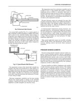
In a remote-bulb controller (Fig. 51), a remote capsule, or
bulb, is attached to a bellows housing by a capillary. The remote
bulb is placed in the controlled medium where changes in
temperature cause changes in pressure of the fill. The capillary
transmits changes in fill pressure to the bellows housing and
the bellows expands or contracts to operate the mechanical
output to the controller. The bellows and capillary also sense
temperature, but because of their small volume compared to
the bulb, the bulb provides the control.
Fig. 51. Typical Remote-Bulb Element.
Two specialized versions of the remote bulb controller are
available. They both have no bulb and use a long capillary (15
to 28 feet) as the sensor. One uses an averaging sensor that is
liquid filled and averages the temperature over the full length
of the capillary. The other uses a cold spot or low temperature
sensor and is vapor filled and senses the coldest spot (12 inches
or more) along its length.
Electronic temperature controllers use low-mass sensing
elements that respond quickly to changes in the controlled
condition. A signal sent by the sensor is relatively weak, but is
amplified to a usable strength by an electronic circuit.
The temperature sensor for an electronic controller may be
a length of wire or a thin metallic film (called a resistance
temperature device or RTD) or a thermistor. Both types of
resistance elements change electrical resistance as temperature
changes. The wire increases resistance as its temperature
increases. The thermistor is a semiconductor that decreases in
resistance as the temperature increases.
Because electronic sensors use extremely low mass, they
respond to temperature changes more rapidly than bimetal or
sealed-fluid sensors. The resistance change is detected by a
bridge circuit. Nickel “A”, BALCO, and platinum are typical
materials used for this type of sensor.
In thermocouple temperature-sensing elements, two
dissimilar metals (e.g., iron and nickel, copper and constantan,
iron and constantan) are welded together. The junction of the
two metals produces a small voltage when exposed to heat.
Connecting two such junctions in series doubles the generated
voltage. Thermocouples are used primarily for high-
temperature applications.
Many special application sensors are available, including
carbon dioxide sensors and photoelectric sensors used in
security, lighting control, and boiler flame safeguard
controllers.
PRESSURE SENSING ELEMENTS
Pressure sensing elements respond to pressure relative to a
perfect vacuum (absolute pressure sensors), atmospheric
pressure (gage pressure sensors), or a second system pressure
(differential pressure sensors), such as across a coil or filter.
Pressure sensors measure pressure in a gas or liquid in pounds
per square inch (psi). Low pressures are typically measured in
inches of water. Pressure can be generated by a fan, a pump or
compressor, a boiler, or other means.
Pressure controllers use bellows, diaphragms, and a number
of other electronic pressure sensitive devices. The medium
under pressure is transmitted directly to the device, and the
movement of the pressure sensitive device operates the
mechanism of a pneumatic or electric switching controller.
Variations of the pressure control sensors measure rate of flow,
quantity of flow, liquid level, and static pressure. Solid state
sensors may use the piezoresistive effect in which increased
pressure on silicon crystals causes resistive changes in the
crystals.
FLAPPER
SPRING
SIGNAL PORT
BRASS TUBE
INVAR ROD
EXTENSION SPRING
SENSOR BODY
C2081
MECHANICAL OUTPUT
TO CONTROLLER
BELLOWS
LIQUID
FILL
CAPILLARY
CONTROLLED
MEDIUM
(E.G., WATER)
BULB
C2083
ENGINEERING MANUAL OF AUTOMATIC CONTROL
CONTROL FUNDAMENTALS
32
FLOW SENSORS
Flow sensors sense the rate of liquid and gas flow in volume
per unit of time. Flow is difficult to sense accurately under all
conditions. Selecting the best flow-sensing technique for an
application requires considering many aspects, especially the
level of accuracy required, the medium being measured, and
the degree of variation in the measured flow.
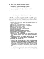
A simple flow sensor is a vane or paddle inserted into the
medium (Fig. 53) and generally called a flow switch. The
paddle is deflected as the medium flows and indicates that the
medium is in motion and is flowing in a certain direction. Vane
or paddle flow sensors are used for flow indication and
interlock purposes (e.g., a system requires an indication that
water is flowing before the system starts the chiller).
MOISTURE SENSING ELEMENTS
Elements that sense relative humidity fall generally into two
classes: mechanical and electronic. Mechanical elements
expand and contract as the moisture level changes and are
called “hygroscopic” elements. Several hygroscopic elements
can be used to produce mechanical output, but nylon is the
most commonly used element (Fig. 52). As the moisture
content of the surrounding air changes, the nylon element
absorbs or releases moisture, expanding or contracting,
respectively. The movement of the element operates the
controller mechanism.
NYLON ELEMENT
RELATIVE HUMIDITY SCALE
C2084
LOW HIGH
ON/OFF SIGNAL
TO CONTROLLER
SENSOR
PIVOT
FLOW
PADDLE (PERPENDICULAR TO FLOW)
C2085
Fig. 52. Typical Nylon Humidity Sensing Element.
Electronic sensing of relative humidity is fast and accurate.
An electronic relative humidity sensor responds to a change
in humidity by a change in either the resistance or capacitance
of the element.
If the moisture content of the air remains constant, the
relative humidity of the air increases as temperature decreases
and decreases as temperature increases. Humidity sensors also
respond to changes in temperature. If the relative humidity is
held constant, the sensor reading can be affected by temperature
changes. Because of this characteristic, humidity sensors
should not be used in atmospheres that experience wide
temperature variations unless temperature compensation is
provided. Temperature compensation is usually provided with
nylon elements and can be factored into electronic sensor
values, if required.
Dew point is the temperature at which vapor condenses. A
dew point sensor senses dew point directly. A typical sensor
uses a heated, permeable membrane to establish an equilibrium
condition in which the dry-bulb temperature of a cavity in the
sensor is proportional to the dew point temperature of the
ambient air. Another type of sensor senses condensation on a
cooled surface. If the ambient dry-bulb and dew point
temperature are known, the relative humidity, total heat, and
specific humidity can be calculated. Refer to the Psychrometric
Chart Fundamentals section of this manual.
Fig. 53. Paddle Flow Sensor.
Flow meters measure the rate of fluid flow. Principle types
of flow meters use orifice plates or vortex nozzles which
generate pressure drops proportional to the square of fluid
velocity. Other types of flow meters sense both total and static
pressure, the difference of which is velocity pressure, thus
providing a differential pressure measurement. Paddle wheels
and turbines respond directly to fluid velocity and are useful
over wide ranges of velocity.
In a commercial building or industrial process, flow meters
can measure the flow of steam, water, air, or fuel to enable
calculation of energy usage needs.
Airflow pickups, such as a pitot tube or flow measuring
station (an array of pitot tubes), measure static and total
pressures in a duct. Subtracting static pressure from total
pressure yields velocity pressure, from which velocity can be
calculated. Multiplying the velocity by the duct area yields
flow. For additional information, refer to the Building Airflow
System Control Applications section of this manual.
Applying the fluid jet principle allows the measurement of
very small changes in air velocity that a differential pressure
sensor cannot detect. A jet of air is emitted from a small tube
perpendicular to the flow of the air stream to be measured.
ENGINEERING MANUAL OF AUTOMATIC CONTROL
CONTROL FUNDAMENTALS
33
The impact of the jet on a collector tube a short distance away
causes a positive pressure in the collector. An increase in
velocity of the air stream perpendicular to the jet deflects the
jet and decreases pressure in the collector. The change in
pressure is linearly proportional to the change in air stream
velocity.
Another form of air velocity sensor uses a microelectronic
circuit with a heated resistance element on a microchip as the
primary velocity sensing element. Comparing the resistance
of this element to the resistance of an unheated element
indicates the velocity of the air flowing across it.
PROOF-OF-OPERATION SENSORS
Proof-of-operation sensors are often required for equipment
safety interlocks, to verify command execution, or to monitor
fan and pump operation status when a central monitoring and
management system is provided. Current-sensing relays,
provided with current transformers around the power lines to
the fan or pump motor, are frequently used for proof-of-
operation inputs. The contact closure threshold should be set
high enough for the relay to drop out if the load is lost (broken
belt or coupling) but not so low that it drops out on a low
operational load.
Current-sensing relays are reliable, require less maintenance,
and cost less to install than mechanical duct and pipe devices.
TRANSDUCERS
Transducers convert (change) sensor inputs and controller
outputs from one analog form to another, more usable, analog
form. A voltage-to-pneumatic transducer, for example, converts
a controller variable voltage input, such as 2 to 10 volts, to a
linear variable pneumatic output, such as 3 to 15 psi. The
pneumatic output can be used to position devices such as a
pneumatic valve or damper actuator. A pressure-to-voltage
transducer converts a pneumatic sensor value, such as 2 to 15
psi, to a voltage value, such as 2 to 10 volts, that is acceptable
to an electronic or digital controller.
CONTROLLERS
Controllers receive inputs from sensors. The controller
compares the input signal with the desired condition, or
setpoint, and generates an output signal to operate a controlled
device. A sensor may be integral to the controller (e.g., a
thermostat) or some distance from the controller.
Controllers may be electric/electronic, microprocessor, or
pneumatic. An electric/electronic controller provides two-
position, floating, or modulating control and may use a
mechanical sensor input such as a bimetal or an electric input
such as a resistance element or thermocouple. A
microprocessor controller uses digital logic to compare input
signals with the desired result and computes an output signal
using equations or algorithms programmed into the controller.
Microprocessor controller inputs can be analog or on/off
signals representing sensed variables. Output signals may be
on/off, analog, or pulsed. A pneumatic controller receives input
signals from a pneumatic sensor and outputs a modulating
pneumatic signal.
ACTUATORS
An actuator is a device that converts electric or pneumatic
energy into a rotary or linear action. An actuator creates a
change in the controlled variable by operating a variety of final
control devices such as valves and dampers.
In general, pneumatic actuators provide proportioning or
modulating action, which means they can hold any position in
their stroke as a function of the pressure of the air delivered to
them. Two-position or on/off action requires relays to switch
from zero air pressure to full air pressure to the actuator.
Electric control actuators are two-position, floating, or
proportional (refer to CONTROL MODES). Electronic
actuators are proportional electric control actuators that require
an electronic input. Electric actuators are bidirectional, which
means they rotate one way to open the valve or damper, and
the other way to close the valve or damper. Some electric
actuators require power for each direction of travel. Pneumatic
and some electric actuators are powered in one direction and
store energy in a spring for return travel.
Figure 54 shows a pneumatic actuator controlling a valve.
As air pressure in the actuator chamber increases, the
downward force (F1) increases, overcoming the spring
compression force (F2), and forcing the diaphragm downward.
The downward movement of the diaphragm starts to close the
valve. The valve thus reduces the flow in some proportion to
the air pressure applied by the actuator. The valve in Figure 54
is fully open with zero air pressure and the assembly is therefore
normally open.
ENGINEERING MANUAL OF AUTOMATIC CONTROL
CONTROL FUNDAMENTALS
34
Fig. 54. Typical Pneumatic Valve Actuator.
A pneumatic actuator similarly controls a damper. Figure
55 shows pneumatic actuators controlling normally open and
normally closed dampers.
DIAPHRAGM
AIR
PRESSURE
SPRING
FLOW
VALVE
ACTUATOR
CHAMBER
F1
F2
C2086
NORMALLY
OPEN DAMPER
ACTUATOR ACTUATOR
SPRING
PISTON
ROLLING
DIAPHRAGM
AIR
PRESSURE
AIR
PRESSURE
NORMALLY
CLOSED DAMPER
C2087
PUSH ROD
CRANK ARM
ACTUATOR
DAMPER
C2721
Fig. 55. Typical Pneumatic Damper Actuator.
Electric actuators are inherently positive positioning. Some
pneumatic control applications require accurate positioning
of the valve or damper. For pneumatic actuators, a positive
positioning relay is connected to the actuator and ensures that
the actuator position is proportional to the control signal. The
positive positioning relay receives the controller output signal,
reads the actuator position, and repositions the actuator
according to the controller signal, regardless of external loads
on the actuator.
Electric actuators can provide proportional or two-position
control action. Figure 56 shows a typical electric damper
actuator. Spring-return actuators return the damper to either
the closed or the open position, depending on the linkage, on a
power interruption.
Fig. 56. Typical Electric Damper Actuator.
AUXILIARY EQUIPMENT
Many control systems can be designed using only a sensor,
controller, and actuator. In practice, however, one or more
auxiliary devices are often necessary.
Auxiliary equipment includes transducers to convert signals
from one type to another (e.g., from pneumatic to electric),
relays and switches to manipulate signals, electric power and
compressed air supplies to power the control system, and
indicating devices to facilitate monitoring of control system
activity.
ENGINEERING MANUAL OF AUTOMATIC CONTROL
CONTROL FUNDAMENTALS
35
CHARACTERISTICS AND ATTRIBUTES OF CONTROL METHODS
Review the columns of Table 4 to determine the characteristics and attributes of pneumatic, electric, electronic, and
microprocessor control methods.
Table 4. Characteristics and Attributes of Control Methods.
Pneumatic Electric Electronic Microprocessor
Naturally
proportional
Requires clean
dry air
Air lines may
cause trouble
below freezing
Explosion proof
Simple, powerful,
low cost, and
reliable actuators
for large valves
and dampers
Simplest
modulating
control
Most common for
simple on-off
control
Integral sensor/
controller
Simple sequence
of control
Broad
environmental
limits
Complex
modulating
actuators,
especially when
spring-return
Precise control
Solid state
repeatability and
reliability
Sensor may be
up to 300 feet
from controller
Simple, remote,
rotary knob
setpoint
High per-loop
cost
Complex
actuators and
controllers
Precise control
Inherent energy management
Inherent high order (proportional plus integral)
control, no undesirable offset
Compatible with building management system.
Inherent database for remote monitoring,
adjusting, and alarming.
Easily performs a complex sequence of control
Global (inter-loop), hierarchial control via
communications bus (e.g., optimize chillers based
upon demand of connected systems)
Simple remote setpoint and display (absolute
number, e.g., 74.4)
Can use pneumatic actuators