In-building Coverage Solutions - KULASEKARAN. P
Bạn đang xem bản rút gọn của tài liệu. Xem và tải ngay bản đầy đủ của tài liệu tại đây (1.98 MB, 31 trang )
12/13/2005 1
In-building Coverage
Solutions
KULASEKARAN. P
Technical Specialist - RF ( Inbuilding Radio Network Planner)
Bangalore. (INDIA)
12/13/2005 2
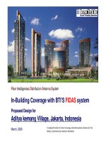
In-Building Solution
• What is an In-Building Solution & Why is it required ?
• It is a process, where in we radiate adequate Mobile signals of one particular Network operator in that entire
building.
In places like basement floors, higher floors of some high rise Buildings, Airports, Corporate offices, Hotels
& Shopping malls we tend to get signals from different cell sites around the building, so subscriber mobile
ping-pong from one cell site to another resulting in high CALL-DROPS & High BER ( Rx Quality )
In some case when the subscriber base increases, the Network operator has difficulty in planning new
BTS. So instead of deploying a Macro Site the operator uses a Micro BTS where in the signal from Micro
BTS will be distributed through out the building using Co-axial cables and distributed antenna system. By
doing so, we will have uniform signal been radiated all through out the building providing an error free
Network connection to all their valuable subscribers present in that building.
In the basement floors there will be absolutely no mobile signals
present, so this problem also can be solved using a distributed antenna
system in that floor.
Network Problems inside Buildings
• High Call Drops - Above 4
th
or 5
th
floors ( Due to Multi cell Hand over )
• High Bit Error Rate - Due to Multipath propagation, Water refraction, Interference from other cell
sites of same operator or other operators
• No network Coverage - Basements, Ground Floors etc. ( Penetration loss)
• Subscriber base increases – If deployment of new BTS sites are not possible
12/13/2005 3
Topics
1. In building Solution Proposals
2. Planning
3. Measurement
4. Implementation
5. In building acceptance testing
12/13/2005 4
General RF Requirements of a customer
• Quality of Service
• Customer requirements > Rx level must be - 80dBm @ 95% Location
Probability
• Server from in building solution in dedicated mode > = 90%
• Call Setup success rate = 98% in the entire building
• Drop Call Rates < = 2%
• DL Rx Quality ( 0 – 2 ) > = 90 % In the entire building
• DL Rx Quality ( 0 – 4 ) > = 95 % In the entire building
• Spillage of signals must be < = -85dBm, on the street and the adjacent
buildings
• Frequency planned for Indoor coverage must be carefully planned
• Parameter settings for IBS must be carefully planned (ex:- hopping frequency,
MAIO, HCS etc.,
12/13/2005 5
Resources
Customers Radio
Network Planner
RF Survey
Engineer
Radio Network
Planner
(documentation)
Sub Contractor
Customer Site
acquisition team
Installation
Planner
Installation
Supervisor
NETWORK OPERATOR
Can be the same person
12/13/2005 6
Process flow
In building survey & implementation roll - out
12/13/2005 7
RF Survey with building floor plan
Rx Lvl
ARFCN
NOKIA NETMONITOR
TEMS LIGHT TOOL
• Nokia phones with net monitor software loaded in it
• Readings need to be taken manually in different locations of the floor, the readings can be mapped on
the floor plans for easy understanding
• TEMS LIGHT is an Ericsson Indoor walk test tool, connect the TEMS to the laptop, load the software and
upload the floor plan of the building. Walk in the floors and record the signal levels, Final report will
have signal details super imposed on the pre-loaded floor plans.
NOTE : For precise EIRP planning at each antenna, its advisable to use TEMS Transmitter for the
survey, but a professional Radio planner is as good as a TEMS Transmitter.
RF Survey Tools
TEMS TRANSMITTER
TOOL
12/13/2005 8
1. In building solution proposal
Radio Network Plan – RNP Report
• Solution description
• Coverage plan
• System diagram
• Power budget calculation
• Proposed antenna location photograph
• System layout on floor plan ( ACAD)
• Measurement results
Passive Distribution
CAT-5 Distribution
12/13/2005 9
RNP Report
Solution Description
Over view
Network Solution passive coaxial & Antenna distribution or LGC network
Coverage Plan (i.e.) Intended Coverage area
Based on the questionnaire or customers requirement, How many levels? Basement , Car park, Lift
lobby, toilets, staff area etc., where all the coverage required
Bill of Materials
Details of How many antennas ( Omni, Panel ), Cable type (1/2” or 7/8”), Splitters, Couplers
Macro/ Micro BTS Accommodation
Type of BTS ( Micro, Macro, flexi talk etc., based on output power )
BTS Location (to be placed in which floor ? Is there any other BTS installed by other network operators ?)
BTS configuration ( 1+1+1 or 2+2+2)
Electrical power supply for BTS
Power to be tapped from ?)
How to bring in E1 connection for the BTS
Should we put a separate electrical meter ? MCB required ? Etc.,
12/13/2005 10
Types of RF distribution techniques
Distributed Antenna System :
• Using passive components like ( Splitters 2way, 3way, 4way , Couplers 6dB, 7dB, 10dB, 15dB, 20dB etc.,)
• Using Active amplifiers ( Line amplifiers etc., )
• Using CAT-5 Cable, Main Hub, Expansion Hub and Remote antenna unit ( RAU’s)
Leaky Cable System :
• Coupling loss
• Attenuation over distance need to be calculated
12/13/2005 11
Passive Distribution Techniques
• Cable lengths more than 50mts has to be a 7/8” (Less loss)
• Use RF couplers for symmetrical power splits
Coupler values are 3dB, 6dB, 7dB, 10dB, 15dB, 20dB & Variable couplers
10 dB Coupler
• Design must have similar power distribution & coupling loss to each antenna
• Best design is to minimize the co-ax length as far as possible
12/13/2005 12
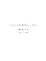
2. Coverage plan
WINDSOR - HALL (I,II & III)
PROPOSED ANTENNA'S
ENTRY
NO SIGNAL
CLIENT ADD RESS:
CUSTOMER NA ME : BSNL
CONTACT PERSON:
PROJECT: IBC SOLUTION
network engineering
sasken
LORDS - HALL (I,II & III)
PROPOSED ANTENNA
BASEMENT
COVERAGE REQUIRED
AREA
TO BE COVERED BY
OUTDOOR CELL