Granular platform reinforced by geosynthetics above cavities laboratory experiments and numerical modeling of load transfer mechanisms
Bạn đang xem bản rút gọn của tài liệu. Xem và tải ngay bản đầy đủ của tài liệu tại đây (7.26 MB, 199 trang )
THÈSE
Pour obtenir le grade de
DOCTEUR DE LA COMMUNAUTE UNIVERSITE
GRENOBLE ALPES
Spécialité : Ingénierie – Matériaux, Mécanique, Energétique,
Environnement, Procédés, Production
Arrêté ministériel : 25 mai 2016
Présentée par
Minh Tuan PHAM
Thèse dirigée par Daniel DIAS et
codirigée par Laurent BRIANÇON
préparée au sein du Laboratoire 3SR
dans l'École Doctorale IMEP2
GRANULAR PLATFORM REINFORCED
BY GEOSYNTHETICS ABOVE CAVITIES
Laboratory experiments and numerical
modeling of load transfer mechanisms
Thèse soutenue publiquement le 04 Avril 2019,
devant le jury composé de :
M. Daniel DIAS
Professeur, Université Grenoble Alpes, Directeur de thốse
M. Laurent BRIANầON
Maợtre de Confộrences, INSA de Lyon, Co-directeur de thèse
M. Nicola MORACI
Professeur, Mediterranean University of Reggio Calabria, Rapporteur
M. Shijin FENG
Professeur, Tongji University, Rapporteur
M. Pascal VILLARD
Professeur, Université Grenoble Alpes, Présidente du Jury
M. Philippe DELMAS
Professeur, CNAM, Examinateur
Mme. Orianne JENCK
Mtre de Conférences, Université Grenoble Alpes, Examinateur
Mme. Claire SILVANI
Mtre de Conférences, INSA de Lyon, Examinateur
M. Abdelkader ABDELOUHAB
Docteur-Ingénieur, Texinov, Invité
GRANULAR PLATFORM REINFORCED BY GEOSYNTHETICS ABOVE CAVITIES
Laboratory experiments and numerical modeling of load transfer mechanisms
By
PHẠM MINH TUẤN
(Email: )
[PhD thesis defended on April 4, 2019 at INSA de Lyon, France]
Granular platform reinforced by geosynthetics above cavities
ACKNOWLEDGMENTS
What can you do for three years? An interesting question with many answers, and for me,
one of the most amazing things is having a wonderful trip to France. My unexpected journey
began due to contact from Grenoble, which gave a hint on a charming country in the West.
Of course, this was not a relaxed tour for me, but I have never regretted my choice.
Indeed, I have encountered many difficulties during my doctorate, and I cannot finish my
work alone. I am enormously grateful to my supervisor, Professor Daniel Dias for his
guidance and encouragement with all aspects of this study. Besides, I wish to express my
sincere appreciation to my co-supervisor Doctor Laurent Brianỗon, a kind person, a
visionary manager and a master in geosynthetic investigations, for guiding me directly at the
LabCom PITAGOR and for his endless support. My both supervisors invested a great deal
of time in my doctorate; I genuinely appreciate their enthusiasm for answering all my
questions. Working with them helps me improve myself, let me find joys in doing research,
truthfully.
This research described in this thesis was performed from February 2016 to December 2018,
in the framework of the new French Laboratory of Technical Innovations applied to
Reinforcement Geosynthetics (PITAGOR) funded in December 2015 by the French National
Research Agency (ANR-15-LCV3-0003). Thanks are also due to the Ministry of Education
and Training of Vietnam, who awarded a scholarship for my thesis. During three years, I
have much enjoyed and benefited from the exceptional environment that exists in the
GEOMAS laboratory, where I stay during my doctorate. Primarily, I very much appreciated
the technicians, who helped me substantially for the laboratory tests. I owe my Vietnamese
friends for their help with the difficulties in life.
Researching over the years at a place far away 10 000 km from home is not easy. To be
honest, after working time, living with my own family in a country of Tour Eiffel is a
beautiful experience. I would like to send my greatest thanks to my parents, my mother-inlaw, who dare to fly for thirteen hours to visit me, to my wife Hạnh as she comes to stay with
me, be on my side, in the most challenging times and of course, to my children, Léo and Léa.
One day, you will be able to read this sentence to know you are the motivation to finish this
work.
From Lyon, a city of lights.
i
Granular platform reinforced by geosynthetics above cavities
Dành tặng bố mẹ, vợ và hai con Léo, Léa của tôi!
ii
Granular platform reinforced by geosynthetics above cavities
SUMMARY
The progressive development of the territory leads to the exploitation of new areas, which
are currently being abandoned because they come up with risks to the safety of users.
This is particularly the case for areas of potential collapse that are related to the presence
of underground cavities. Among the many preventative solutions, geosynthetic
reinforcement prevents localized collapse. This solution is widely used for both its
economic and environmental benefits, as well as for its ease and speed of setting up.
However, the existing design methods for granular platforms reinforced by geosynthetic
are based on various simplifying assumptions and do not take the complexity of the
problem into account. These methods do not consider, for example, the influence of how
the cavity is opened, the expansion of granular soil above the cavity, or the real stress
distribution on the geosynthetic after opening the cavity.
The present study tries to improve the design methods by analyzing mechanisms developed
inside the reinforced granular platform on the basis of an experimental study coupled with
numerical simulations.
An experimental device was developed to simulate the opening of a cavity under a
platform reinforced by geosynthetic. This device allows simulating two types of opening:
a trapdoor or a concentric opening, for various heights of platforms. The mechanisms are
studied by measuring the deflection of the geosynthetic, the settlement at the surface and
the stress distribution applied on the geosynthetic. A Finite element model was calibrated
on the experimental results then used to analyze mechanisms finely for many
configurations.
This experimental and numerical study allows improving the understanding of the stress
distribution, the soil expansion above the cavity and experimentally validated the
influence of the opening mode on the mechanisms. Based on these results, proposals are
formulated to improve the design of geosynthetic-reinforced platforms subject to
localized collapse.
iii
Granular platform reinforced by geosynthetics above cavities
RÉSUMÉ
L’aménagement progressif du territoire conduit à l’exploitation de nouvelles zones,
actuellement délaissées, car présentant des risques pour la sécurité des usagers. C’est
notamment le cas des zones d’effondrements potentiels qui sont liées à la présence de cavités
souterraines. Parmi les nombreuses solutions préventives, le renforcement géosynthétique
permet de prévenir les risques d’effondrements localisés. Cette solution de renforcement est
largement utilisée à la fois pour ses avantages économiques et environnementaux, que pour
sa facilité et rapidité de mise en œuvre. Néanmoins, les méthodes de conception existantes
des plateformes granulaires renforcées par géosynthétiques sont fondées sur diverses
hypothèses simplificatrices et ne prennent pas en compte toute la complexité du problème.
En effet, ces méthodes ne considèrent pas, par exemple, l’influence du mode d’ouverture de
la cavité, le foisonnement du sol granulaire au droit de la cavité ou encore la distribution de
charge sur le géosynthétique après ouverture de la cavité.
La présente étude tente d’améliorer les méthodes de dimensionnement en analysant les
mécanismes développés dans la plateforme granulaire renforcée sur la base d’une campagne
expérimentale couplée à des modélisations numériques.
Un dispositif expérimental a été développé pour simuler l’ouverture d’une cavité sous une
plateforme renforcée par géosynthétique. Ce dispositif permet de simuler deux modes
d’ouverture : une trappe qui s’abaisse ou une ouverture concentrique, pour différentes
hauteurs de plateformes. Les mécanismes de renforcement sont étudiés en mesurant la
déflexion du géosynthétique, le tassement en surface et la distribution de contrainte verticale
qui s’applique sur le géosynthétique. Un modèle numérique par éléments finis a été calibré
sur les résultats expérimentaux puis utilisé pour analyser finement les mécanismes pour de
nombreuses configurations.
Cette étude expérimentale et numérique a permis d’améliorer la compréhension des
mécanismes de transfert de charge et de foisonnement dans la zone effondrée et de valider
expérimentalement l’influence du mode d’ouverture sur les mécanismes. Sur la base de ces
résultats, des propositions sont formulées pour améliorer le dimensionnement des
plateformes renforcées par géosynthétiques soumises à des effondrements localisés.
iv
Granular platform reinforced by geosynthetics above cavities
TABLE OF CONTENTS
ACKNOWLEDGEMENTS ..........................................................................................................................i
SUMMARY ........................................................................................................................................... iii
RÉSUMÉ ............................................................................................................................................... iv
TABLE OF CONTENTS ............................................................................................................................. v
LIST OF FIGURES .................................................................................................................................... x
LIST OF TABLES ................................................................................................................................... xiv
NOMENCLATURE................................................................................................................................. xv
CHAPTER 1. INTRODUCTION .................................................................................................................1
1.1. GEOSYNTHETIC-REINFORCED SOILS ................................................................................................. 2
1.1.1. General definition of geosynthetics .......................................................................................... 2
1.1.2. Geosynthetic-reinforced soils applications ............................................................................... 4
1.2. OVERVIEW OF GEOSYNTHETIC-REINFORCED EMBANKMENT SPANNING CAVITIES ......................... 6
1.3. PROJECTS OF REINFORCED EMBANKMENT SPANNING CAVITIES ..................................................... 8
1.3.1. High-speed railway, LGV Est, Lorraine, France (Tencate, 2010) ............................................... 8
1.3.2. Public park, Arras, France (Texinov, 2018a) ............................................................................. 9
1.3.3. Football field, Barcelona, Spain (Tencate, 2010) .................................................................... 10
1.3.4. Embankment on mining area, Estonia (Texinov, 2018b) ........................................................ 11
1.3.5. Discussion on the design methods.......................................................................................... 12
1.4. OBJECTIVES AND SCOPE OF THESIS ................................................................................................ 13
1.5. THESIS OUTLINE ............................................................................................................................. 14
CHAPTER 2. LITERATURE REVIEW ........................................................................................................ 15
2.1. INTRODUCTION .............................................................................................................................. 16
2.2. SOIL ARCHING THEORIES ................................................................................................................ 16
2.2.1. Terzaghi .................................................................................................................................. 16
2.2.2. Handy ..................................................................................................................................... 18
2.2.3. Vardoulakis ............................................................................................................................. 19
2.2.5. Arching theories comparison .................................................................................................. 20
2.3. REINFORCED STRUCTURE MECHANISMS ....................................................................................... 22
2.3.1. Membrane effect and friction behavior ................................................................................. 22
2.3.2. Load acting on the geosynthetic sheet ................................................................................... 23
2.3.3. Soil expansion ......................................................................................................................... 23
2.4. EXISTING ANALYTICAL METHODS ................................................................................................... 24
v
Granular platform reinforced by geosynthetics above cavities
2.4.1. British Standard (2010) ........................................................................................................... 24
2.4.1.1. Principles.............................................................................................................................. 24
2.4.1.2. Design .................................................................................................................................. 26
2.4.2. French recommendations ....................................................................................................... 27
2.4.2.1. RAFAEL ................................................................................................................................. 27
2.4.2.2. New recommendations XP G 38063-2 ................................................................................. 29
2.4.3. EBGEO (1997, 2011) ............................................................................................................... 33
2.4.3.1. Principles.............................................................................................................................. 33
2.4.3.2. Design .................................................................................................................................. 34
2.4.4. Design methods comparison .................................................................................................. 38
2.4.5. Other methods and summary ................................................................................................. 42
2.4.5.1. Specific developments ......................................................................................................... 42
2.4.5.2. Summary .............................................................................................................................. 43
2.5. KEY EXPERIMENTAL STUDIES .......................................................................................................... 44
2.5.1. Experimental testing of arching effect by Costa et al., 2009 .................................................. 44
2.5.2. Arching effect study by Pardo and Sáez, 2014........................................................................ 46
2.5.3. Laboratory tests of soil arching by Rui et al., 2016a............................................................... 47
2.5.4. Model tests of interaction between soil and geosynthetics of Zhu et al., 2012 ..................... 48
2.5.5. Experimental and numerical tests on geosynthetic of Huang et al., 2015 ............................. 50
2.5.6. Full-scale experiment of cavity by Huckert et al., 2016 .......................................................... 52
2.5.7. Other experimental studies .................................................................................................... 53
2.5.8. Summary of experimental studies .......................................................................................... 54
2.6. NUMERICAL ANALYSIS .................................................................................................................... 56
2.6.1. Finite element method............................................................................................................ 57
2.6.2. Key numerical studies ............................................................................................................. 58
2.6.2.1. Experimentation and numerical simulation of Schwerdt et al., 2004 .................................. 58
2.6.2.2. Finite element models of Potts (2007) ................................................................................. 60
2.6.2.3. Numerical approach by Villard et al. (2016) ........................................................................ 62
2.6.2.4. Numerical approach of Yu and Bathurst (2017) .................................................................. 63
2.6.2.5. Other numerical studies....................................................................................................... 66
2.6.3. Summary of numerical studies ............................................................................................... 68
2.7. CONCLUSIONS ................................................................................................................................ 70
CHAPTER 3. LABORATORY EXPERIMENT ............................................................................................. 73
3.1. INTRODUCTION .............................................................................................................................. 74
3.2. LABORATORY TEST ......................................................................................................................... 74
3.2.1. Description .............................................................................................................................. 74
3.2.2. Model setup ............................................................................................................................ 75
vi
Granular platform reinforced by geosynthetics above cavities
3.3.2.1. Device .................................................................................................................................. 75
3.2.2.2. Tested soils .......................................................................................................................... 76
3.2.2.3. Tested geosynthetics ........................................................................................................... 77
3.2.3. Monitoring.............................................................................................................................. 78
3.2.3.1. Displacement sensors .......................................................................................................... 78
3.2.3.2. Tactile pressure sensor ........................................................................................................ 80
3.2.4. Test program .......................................................................................................................... 83
3.2.4.1. Platform set-up.................................................................................................................... 83
3.2.4.2. Displacement measurement procedure .............................................................................. 83
3.2.4.3. Stress measurement procedure ........................................................................................... 83
3.2.5. Analysis procedures ................................................................................................................ 84
3.2.5.1. Soil expansion ...................................................................................................................... 84
3.2.5.2. Shape of collapsed soils ....................................................................................................... 86
3.2.5.3. Load distribution ................................................................................................................. 87
3.2.5.4. Efficiency of load transfer .................................................................................................... 88
3.3. RESULTS AND ANALYZES ................................................................................................................ 89
3.3.1. Settlement and deflection ...................................................................................................... 89
3.3.2. Influence of experimental conditions ..................................................................................... 91
3.3.2.1. Repeatability ....................................................................................................................... 91
3.3.2.2. Opening methods ................................................................................................................ 91
3.3.2.3. H/D ratio .............................................................................................................................. 92
3.3.3. Expansion analysis .................................................................................................................. 94
3.3.3.1. Shape of deformed zone ...................................................................................................... 94
3.3.3.2. Comparison of coefficients estimated by different methods ............................................... 95
3.3.3.3. Influence of density ............................................................................................................. 97
3.3.3.4. Conclusion on the expansion coefficient ............................................................................. 98
3.3.4. Load transfer mechanisms over evolving cavity (Program 1) ................................................ 99
3.3.4.1. Load transfer on anchorage areas ...................................................................................... 99
3.3.4.2. Comparison between cavity area and anchorage area ..................................................... 101
3.3.5. Load transfer mechanisms over existing cavity (Program 2) ............................................... 105
3.4. IMPROVEMENT TO BRING TO THE EXPERIMENTATION ............................................................... 108
3.5. CONCLUSIONS .............................................................................................................................. 109
CHAPTER 4. NUMERICAL SIMULATIONS ............................................................................................ 111
4.1. INTRODUCTION ............................................................................................................................ 112
4.2. FINITE ELEMENT ANALYSIS ........................................................................................................... 112
4.2.1. Numerical modeling ............................................................................................................. 112
4.2.1.1. Basic concept ..................................................................................................................... 112
vii
Granular platform reinforced by geosynthetics above cavities
4.2.1.2. Soil constitutive models ..................................................................................................... 114
4.2.1.3. Materials ........................................................................................................................... 115
4.2.1.4. Geosynthetics elements ..................................................................................................... 116
4.2.1.5. Interface elements ............................................................................................................. 116
4.2.2. Numerical analysis of the physical model ............................................................................. 117
4.2.2.1. Initial and boundary conditions ......................................................................................... 117
4.2.2.2. Cavities opening methods.................................................................................................. 118
4.2.2.3. Calculation phases ............................................................................................................. 118
4.2.3. Sensitivity analysis of input parameters ............................................................................... 118
4.2.3.1. Overlying soil characteristics ............................................................................................. 119
4.2.3.2. Tensile stiffness of geosynthetics....................................................................................... 120
4.3. KINEMATIC ANALYSIS OF EMBANKMENTS ................................................................................... 122
4.3.1. Surface settlement ................................................................................................................ 122
4.3.2. Geosynthetic deflection ........................................................................................................ 124
4.3.3. Influence of the soil constitutive model ................................................................................ 128
4.4. SOIL EXPANSION ANALYSIS ........................................................................................................... 129
4.4.1. Expansion coefficient ............................................................................................................ 129
4.4.2. Effect of geometrical configurations .................................................................................... 134
4.5. LOAD TRANSFER ANALYSIS ........................................................................................................... 136
4.5.1. Load transfer on cavity area ................................................................................................. 136
4.5.2. Efficiency of the load transfer ............................................................................................... 141
4.5.3. Effect of the cavity diameter ................................................................................................ 143
4.5.4. Effect of the surcharges ........................................................................................................ 146
4.6. CONCLUSIONS .............................................................................................................................. 149
CHAPTER 5. RESULTS DISCUSSION .................................................................................................... 151
5.1. INTRODUCTION ............................................................................................................................ 152
5.2. LOAD DISTRIBUTION ..................................................................................................................... 152
5.2.1. Shape of the load distribution .............................................................................................. 152
5.2.2. Earth pressure coefficient ..................................................................................................... 153
5.2.3. Load transfer efficiency ........................................................................................................ 154
5.3. DEFLECTION BEHAVIORS .............................................................................................................. 155
5.3.1. Shape of subsidence zone ..................................................................................................... 155
5.3.2. Influences on vertical displacements .................................................................................... 155
5.3.3. Geosynthetic strain ............................................................................................................... 155
5.3.4. Equal settlement plane ......................................................................................................... 156
5.4. SOIL EXPANSION COEFFICIENT ..................................................................................................... 156
5.5. DESIGN PROCEDURE ..................................................................................................................... 157
viii
Granular platform reinforced by geosynthetics above cavities
5.5.1. Cavity characteristics estimation.......................................................................................... 157
5.5.2. Mechanical parameters measurement ................................................................................ 158
5.5.3. Geosynthetic tensile stiffness determination ....................................................................... 158
CHAPTER 6. CONCLUSIONS ............................................................................................................... 159
6.1. EXPERIMENTAL APPROACH .......................................................................................................... 160
6.2. NUMERICAL APPROACH ............................................................................................................... 160
6.3. RECOMMENDATIONS ................................................................................................................... 161
REFERENCES ...................................................................................................................................... 163
APPENDIX A ...................................................................................................................................... 171
APPENDIX B ...................................................................................................................................... 175
ix
Granular platform reinforced by geosynthetics above cavities
LIST OF FIGURES
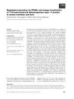
FIGURE 1.1. GEOSYNTHETICS FUNCTIONS (IGS, 2018A) .......................................................................................... 3
FIGURE 1.2. REINFORCED SOIL APPLICATIONS......................................................................................................... 5
FIGURE 1.3. LOAD DISTRIBUTION IN PILED EMBANKMENTS (VAN EEKELEN, 2015) ........................................................ 6
FIGURE 1.4. DIFFERENT CAUSES OF CAVITIES (URETEK) .......................................................................................... 7
FIGURE 1.5. TYPICAL CROSS-SECTION THROUGH THE REINFORCED TRACK STRUCTURE, LGV EST, LORRAINE, FRANCE (TENCATE,
2010) ................................................................................................................................................... 9
FIGURE 1.6. CROSS SECTION DETAILS THROUGH THE REINFORCED FOUNDATION, BARCELONA, SPAIN (TENCATE, 2010) ..... 11
FIGURE 1.7. EUROPEAN ROUTE E20, TALLINN-NARVA SECTION, ESTONIA (TEXINOV, 2018B) ...................................... 12
FIGURE 2.1. THE PRINCIPLE OF THE ARCHING EFFECT (TERZAGHI, 1943) ................................................................... 17
FIGURE 2.2. STATE OF THE STRESS AT A BOUNDARY POINT OF THE SLIDING MASS REPRESENTED IN MOHR CIRCLE (HANDY,
1985) ................................................................................................................................................. 19
FIGURE 2.3. STRESS APPLIED TO THE CAVITY IN DIFFERENT METHODS OF CALCULATION ................................................. 21
FIGURE 2.4. MEMBRANE EFFECT (BRIANÇON AND VILLARD, 2008) ......................................................................... 22
FIGURE 2.5. DEFINITION OF EFFICIENCY BASED ON WS AND FG ................................................................................. 23
FIGURE 2.6. CONCEPTUAL ROLE (BS8006, 2010) ............................................................................................... 25
FIGURE 2.7. DESCRIPTION OF PARAMETERS FOR DESIGN METHOD (BS8006, 2010) ................................................... 25
FIGURE 2.8. MECHANISM AT THE EDGE OF THE CAVITY (BRIANÇON AND VILLARD, 2008)............................................. 30
FIGURE 2.9. EQUILIBRIUM OF AN ELEMENTARY SECTION: UA ≤ U0 (A) AND UA > U0 (B), VILLARD AND BRIANÇON (2008). 30
FIGURE 2.10. DESIGNATIONS ........................................................................................................................... 33
FIGURE 2.11. MODEL CONFIGURATION OF COSTA ET AL. (2009) ............................................................................ 45
FIGURE 2.12. TRAPDOOR DEVICE SCHEME OF PARDO AND SÁEZ (2014) ................................................................... 46
FIGURE 2.13. LOAD DISTRIBUTION ON RIGID SUPPORT OF THE BOX (PARDO AND SÁEZ, 2014) ...................................... 47
FIGURE 2.14. TEST SETUP (RUI ET AL., 2016A) .................................................................................................... 48
FIGURE 2.15. LAYOUT OF MODEL TESTS (ZHU ET AL., 2012) .................................................................................. 49
FIGURE 2.16. ILLUSTRATION OF FIRST (A) AND SECOND (B) TEST STRATEGIES (ZHU ET AL., 2012) .................................. 50
FIGURE 2.17. PHOTO OF TEST BY HUANG ET AL., 2015 ......................................................................................... 51
FIGURE 2.18. SCHEMA OF FULL-SCALE EXPERIMENT (HUCKERT ET AL., 2016) ............................................................ 52
FIGURE 2.19. ANALYTICAL AND EXPERIMENTAL GEOSYNTHETIC STRAIN (HUCKERT ET AL., 2016) ................................... 52
x
Granular platform reinforced by geosynthetics above cavities
FIGURE 2.20. MODEL OF THE LAYERS FOR THE PLAXIS CALCULATIONS (SCHWERDT ET AL., 2004) ................................ 59
FIGURE 2.21. EXPERIMENT TEST SET-UP (POTTS, 2007)........................................................................................ 61
FIGURE 2.22. KEY RESULTS OF NUMERICAL SIMULATIONS (VILLARD ET AL., 2016) ...................................................... 63
FIGURE 2.23. SIMULATION WORKS OF YU AND BATHURST (2017) .......................................................................... 65
FIGURE 3.1. EXPERIMENTAL DEVICE ................................................................................................................... 76
FIGURE 3.2. OPENING METHODS: TRAPDOOR PROCEDURE (A), AND PROGRESSIVE PROCEDURE (B) ................................. 76
FIGURE 3.3. TESTED GEOSYNTHETICS ................................................................................................................. 77
FIGURE 3.4. LOCATION OF DISPLACEMENT MONITORING SENSORS ........................................................................... 79
FIGURE 3.5. PHOTOGRAPHS OF DISPLACEMENT SENSORS ....................................................................................... 79
FIGURE 3.6. INTERFACE OF SOFTWARE FOR DISPLACEMENT MEASUREMENT ............................................................... 80
FIGURE 3.7. PHOTOGRAPH OF TPS ON THE ANCHORAGE AREA OF THE CAVITY ............................................................ 81
FIGURE 3.8. LOCATIONS OF TPS AT THE ANCHORAGE, THE BORDER AND THE CENTER OF CAVITY .................................... 81
FIGURE 3.9. LOCATION OF TPS BEFORE AND AFTER THE CAVITY OPENING .................................................................. 82
FIGURE 3.10. CHAMELEON TVP SOFTWARE INTERFACE ......................................................................................... 82
FIGURE 3.11. ILLUSTRATION OF VOLUMES OF SOIL SETTLEMENT AND GEOSYNTHETIC DEFLECTION .................................. 86
FIGURE 3.12. TWO PARTS OF DEFORMATION CURVES ............................................................................................ 86
FIGURE 3.13. SHAPE OF COLLAPSED SOIL ............................................................................................................ 87
FIGURE 3.14. SELECTED AREAS ON TPS (1-5) ..................................................................................................... 87
FIGURE 3.15. A TYPICAL COMPARISON OF DEFLECTED GEOSYNTHETIC (FINE SAND & WOVEN GSY) ............................... 90
FIGURE 3.16. GEOSYNTHETIC DEFLECTION OF WOVEN GEOSYNTHETIC TESTS .............................................................. 92
FIGURE 3.17. GEOSYNTHETIC DEFLECTION OF NONWOVEN GEOSYNTHETIC TESTS ........................................................ 92
FIGURE 3.18. SURFACE SETTLEMENT OF WOVEN GEOSYNTHETIC TESTS ..................................................................... 93
FIGURE 3.19. ESTIMATION OF EQUAL SETTLEMENT PLANE FOR WOVEN GEOSYNTHETIC ................................................ 93
FIGURE 3.20. SURFACE SETTLEMENT OF NONWOVEN GEOSYNTHETIC TESTS ............................................................... 94
FIGURE 3.21. ESTIMATION OF THE EQUAL SETTLEMENT PLANE FOR NONWOVEN GEOSYNTHETIC .................................... 94
FIGURE 3.22. SHAPE FORMS OF EMBANKMENT: T – TRUNCATED SHAPE, C – CYLINDRICAL SHAPE .................................. 95
FIGURE 3.23. COMPARISON BETWEEN TWO MODELS TO FIT THE CURVES OF MEASUREMENT DATA ................................. 96
FIGURE 3.24. COMPARISON OF CE VALUES ESTIMATED USING TWO DIFFERENT METHODS FOR MODE A TESTS.................. 97
FIGURE 3.25. COMPARISON OF CE VALUES COMPUTED USING TWO DIFFERENT METHODS FOR MODE B TESTS ................. 97
xi
Granular platform reinforced by geosynthetics above cavities
FIGURE 3.26. CE VALUES OF COARSE SAND TESTED MODE B, H/D = 0.5, AND WOVEN GSY ......................................... 98
FIGURE 3.27. EFFICIENCY OF TESTS WITH AN H/D VALUE OF 0.5 AND WOVEN GEOSYNTHETICS ................................... 100
FIGURE 3.28. TPS LOCATED AT THE BORDER OF THE CAVITY.................................................................................. 101
FIGURE 3.29. STRESS VARIATION MEASURED BY TPS PLACED AT CAVITY BORDER ...................................................... 101
FIGURE 3.30. STRESS VARIATION MEASURED BY TPS COMPARING TO DIFFERENT LOCATIONS....................................... 102
FIGURE 3.31. INCREASE OF STRESS AFTER CAVITY OPENING (PROGRAM 1) ............................................................... 103
FIGURE 3.32. COMPARISON OF STRESS RATIO BETWEEN PROGRAM 2 (MODE A) ...................................................... 105
FIGURE 3.33. COMPARISON OF STRESS RATIO BETWEEN PROGRAM 2 (MODE B) ...................................................... 105
FIGURE 3.34. COMPARISON OF LOAD DISTRIBUTION BETWEEN PROGRAM 1 AND 2 (MODE A) .................................... 106
FIGURE 3.35. COMPARISON OF LOAD DISTRIBUTION BETWEEN PROGRAM 1 AND 2 (MODE B) .................................... 106
FIGURE 3.36. SHAPES OF DEFLECTED GEOSYNTHETIC OF MODE B (PROGRAM 2) ...................................................... 107
FIGURE 3.37. STRETCHING OF GEOSYNTHETICS ON TEST TABLE .............................................................................. 108
FIGURE 4.1. GEOMETRICAL CONFIGURATION FOR THE NUMERICAL CALCULATION ...................................................... 113
FIGURE 4.2. POSITIONS OF INTERFACE ELEMENTS USED IN THE NUMERICAL MODELING ............................................... 117
FIGURE 4.3. VARIATION OF SURFACE SETTLEMENT AND DEFLECTED GEOSYNTHETICS DUE TO CHANGING OF DILATANCY ANGLE
AND EARTH PRESSURE COEFFICIENT .......................................................................................................... 120
FIGURE 4.4. VARIATION OF CE DUE TO CHANGING OF DILATANCY ANGLE AND EARTH PRESSURE COEFFICIENT .................. 120
FIGURE 4.5. VARIATION OF SURFACE SETTLEMENT AND DEFLECTED GEOSYNTHETICS DUE TO CHANGING OF GEOSYNTHETIC
STIFFNESS ........................................................................................................................................... 121
FIGURE 4.6. VARIATION OF CE DUE TO CHANGING OF GEOSYNTHETIC STIFFNESS ....................................................... 121
FIGURE 4.7. COMPARISON OF SURFACE SETTLEMENT BETWEEN EXPERIMENTAL AND NUMERICAL RESULTS ...................... 122
FIGURE 4.8. COMPARISON OF SURFACE SETTLEMENT BETWEEN EXPERIMENTAL AND NUMERICAL RESULTS ...................... 123
FIGURE 4.9. COMPARISON OF DEFLECTED GEOSYNTHETICS BETWEEN EXPERIMENTAL AND NUMERICAL RESULTS .............. 125
FIGURE 4.10. COMPARISON BETWEEN EXPERIMENTAL AND NUMERICAL RESULTS FOR THE MAXIMUM GEOSYNTHETICS
DEFLECTION ........................................................................................................................................ 126
FIGURE 4.11. COMPARISON OF GEOSYNTHETIC STRAINS AT CAVITY AREA BETWEEN TWO MODES OF CAVITY OPENING (FINE
SAND AND WOVEN GEOSYNTHETIC) ......................................................................................................... 127
FIGURE 4.12. EQUAL SETTLEMENT PLANE CALCULATED BY PLAXIS ........................................................................ 128
FIGURE 4.13. DIFFERENCE OF THE MAXIMAL VERTICAL DISPLACEMENTS OF SURFACE SETTLEMENT AND GEOSYNTHETICS ... 129
FIGURE 4.14. COMPARISON OF CE BETWEEN EXPERIMENTAL AND NUMERICAL RESULTS ............................................. 130
xii
Granular platform reinforced by geosynthetics above cavities
FIGURE 4.15. CHANGE IN VOID RATIO WITHIN THE OVERLYING SOILS OVER REINFORCEMENT SYSTEMS (FINE SAND & WOVEN
GSY)................................................................................................................................................. 132
FIGURE 4.16. AVERAGE VALUES OF VOID RATIO IN THE COLLAPSED SOIL .................................................................. 132
FIGURE 4.17. CHANGE IN DEVIATORIC STRAIN WITHIN THE OVERLYING SOILS OVER REINFORCEMENT SYSTEMS (FINE SAND &
WOVEN GSY) ..................................................................................................................................... 133
FIGURE 4.18. VARIATION OF SURFACE SETTLEMENT (A) AND DEFLECTED GEOSYNTHETICS (B) DUE TO CHANGING OF CAVITY
DIAMETER, CASES OF FINE SAND .............................................................................................................. 134
FIGURE 4.19. VARIATION OF CE DUE TO CHANGING OF CAVITY DIAMETER ............................................................... 135
FIGURE 4.20. NUMERICAL LOAD DISTRIBUTION ON CAVITY CALCULATED FOR FINE SAND TESTS..................................... 137
FIGURE 4.21. NUMERICAL LOAD DISTRIBUTION ON CAVITY CALCULATED FOR COARSE SAND TESTS ................................ 138
FIGURE 4.22. PRINCIPAL STRESS WITHIN THE FINE SAND OVER WOVEN GEOSYNTHETIC ............................................... 139
FIGURE 4.23. PRINCIPAL STRESS WITHIN THE FINE SAND OVER WOVEN GEOSYNTHETIC WITH EVOLUTIONS OF THE TWO CAVITY
OPENING ............................................................................................................................................ 139
FIGURE 4.24. ESTIMATION OF THE STRESS RATIOS OF FINE SAND OVER GSY AFTER CAVITY OPENING ............................. 140
FIGURE 4.25. COMPARISON OF THE LOAD TRANSFER EFFICIENCY BETWEEN EXPERIMENTAL, DEM AND FEM RESULTS, CASES OF
FINE SAND TESTS .................................................................................................................................. 142
FIGURE 4.26. NUMERICAL LOAD TRANSFER EFFICIENCY, CASES OF COARSE SAND TESTS .............................................. 142
FIGURE 4.27. COMPARISON OF FINAL LOAD APPLIED ON GEOSYNTHETICS BETWEEN ANCHORAGE AND CAVITY AREAS ....... 143
FIGURE 4.28. VARIATION OF THE LOAD DISTRIBUTION DUE TO THE CAVITY DIAMETER VARIATION: MODE A ................... 144
FIGURE 4.29. VARIATION OF THE LOAD DISTRIBUTION DUE TO THE CAVITY DIAMETER VARIATION: MODE B ................... 145
FIGURE 4.30. VARIATION OF THE LOAD TRANSFER EFFICIENCY DUE TO THE CAVITY DIAMETER VARIATION ....................... 146
FIGURE 4.31. SURCHARGE APPLIED ON OVERLYING SOIL ABOVE EXISTING CAVITY ...................................................... 147
FIGURE 4.32. COMPARISON BETWEEN THE FINAL LOAD ACTING ON GEOSYNTHETIC (FINE SAND AND PROGRAM 2) .......... 147
FIGURE 4.33. COMPARISON OF THE LOAD DISTRIBUTION OBTAINED BY THE NUMERICAL MODELS BETWEEN PROGRAM 1 AND
PROGRAM 2 ....................................................................................................................................... 148
FIGURE 5.1. COMPARISON OF STRESS RATIOS BETWEEN THE EXPERIMENT OF MODE A AND TERZAGHI’S THEORY ............ 153
xiii
Granular platform reinforced by geosynthetics above cavities
LIST OF TABLES
TABLE 2.1. CHARACTERISTICS OF FILL SOILS IN THE COMPARISON ............................................................................. 20
TABLE 2.2. DESIGN PARAMETERS OF BRITISH STANDARD (2010) ............................................................................ 26
TABLE 2.3. DESCRIPTION OF THE DESIGN PARAMETER OF RAFAEL METHOD .............................................................. 29
TABLE 2.4. DESIGN PARAMETERS OF EBGEO STANDARD (2011) ............................................................................ 37
TABLE 2.5. PHYSICAL CHARACTERISTICS OF THE CURRENT DESIGN METHODS ............................................................... 38
TABLE 2.6. PARAMETERS FOR THE COMPARISON OF DESIGN METHODS...................................................................... 39
TABLE 2.7. RESULTS OF DESIGN METHODS IN CASE OF H/D = 0.5 ............................................................................ 40
TABLE 2.8. RESULTS OF DESIGN METHODS IN CASE OF H/D = 1.0 ............................................................................ 41
TABLE 2.9. SUMMARY OF MAIN CURRENT OUTCOMES OF EXPERIMENT STUDIES .......................................................... 55
TABLE 2.10. SURFACE SETTLEMENT AND MATERIAL DEFLECTION VALUES ARE TAKEN FROM MEASUREMENT AND PLAXIS
(SCHWERDT ET AL., 2004) ...................................................................................................................... 59
TABLE 2.11. SUMMARY OF MAIN CURRENT OUTCOMES OF NUMERICAL STUDIES ......................................................... 69
TABLE 3.1. TESTED SOIL CHARACTERISTICS........................................................................................................... 77
TABLE 3.2. GEOSYNTHETIC CHARACTERISTICS ....................................................................................................... 77
TABLE 3.3. WOVEN GEOSYNTHETIC TEST RESULTS ................................................................................................. 89
TABLE 3.4. NONWOVEN GEOSYNTHETIC TEST RESULTS ........................................................................................... 90
TABLE 3.5. REPEATABILITY TESTS ....................................................................................................................... 91
TABLE 3.6. COEFFICIENT OF DETERMINATION COMPARISON BETWEEN TWO MODELS ................................................... 95
TABLE 3.7. STRESS VARIATION IN FINE SAND TESTS CALCULATED FROM ANCHORAGE AREAS TESTS ................................... 99
TABLE 3.8. STRESS VARIATION IN COARSE SAND TESTS CALCULATED FROM ANCHORAGE AREAS TESTS ............................ 100
TABLE 3.9. EFFICIENCY OF LOAD TRANSFER ........................................................................................................ 104
TABLE 4.1. PARAMETERS FOR THE MOHR-COULOMB CONSTITUTIVE MODEL ............................................................ 115
TABLE 4.2. PARAMETERS FOR THE HARDENING SOIL CONSTITUTIVE MODEL FOR FINE SAND ......................................... 115
TABLE 4.3. PARAMETERS FOR INTERFACES ELEMENTS .......................................................................................... 117
TABLE 4.4. VALUES OF CE CALCULATED BY NUMERICAL AND EXPERIMENT TESTS........................................................ 131
TABLE 5.1. SUMMARY OF INFLUENCED FACTORS ON LOAD TRANSFER EFFICIENCY....................................................... 154
TABLE 5.2. AVERAGE EXPANSION COEFFICIENT WITH THE CAVITY DIAMETER = 0.5 M ................................................. 156
xiv
Granular platform reinforced by geosynthetics above cavities
NOMENCLATURE
2-D
-
Two-dimensional space
3-D
-
Three-dimensional space
a, a′1 , a′2
-
Interaction coefficients relating to the soil/reinforcement bond angle
𝑓𝑓𝑠
-
Partial load factor for soil
𝑓𝑀
Vertical displacement of the geosynthetic at point M
𝑓𝑑
-
Partial load factor for externally applied load
𝑓𝑚𝑠
-
Partial material factor
𝑓𝑛
-
Partial factor governing the economic ramifications of failure
𝑓𝑝
-
Partial factor applied to the pull-out resistance of the reinforcement
c’, ck
kPa
Cohesion
Cc
-
Curvature coefficient
Ce, Ce1, Ce2
-
Expansion coefficient
Cu
-
Uniformity coefficient
D
m
Cavity diameter
D50
-
Intercept for 50% of cumulative mass
Dc
m
Inner diameter of cylinder
dg
m
Maximal deflection of geosynthetics (m)
Dmax
mm
Maximum size of the grains
DR
-
Relative density
Ds
m
Diameter of surface deformation
ds
m
Maximal surface settlement
E
%
Efficiency of load transfer
e0
-
Void ratio
E50
MPa
Secant modulus
Ecmd,d
kN/m
Design value of actions for geosynthetic cross machine direction
emax
-
Void ratio of the soil at its loosest condition
xv
Granular platform reinforced by geosynthetics above cavities
Emd,d
kN/m
Design value of actions for geosynthetic machine direction
emin
-
Void ratio of the soil at its densest condition
Eoed
MPa
Oedometer modulus
Eur
MPa
Unloading/reloading stiffness
E Y, E i
MPa
Young’s modulus
H, H1, H2
m
Embankment height (m)
H/D
-
Ratio between embankment height and cavity diameter
Hcmd,d
kN/m
Design value of horizontal tensile forces for geosynthetic cross
machine direction
Hmd,d
kN/m
Design value of horizontal tensile forces for geosynthetic machine
direction
HS
-
Horizontal sensor (displacement sensor)
J
kN/m
Tensile stiffness per unit width of geosynthetic fabric
Jcmd
kN/m
Transverse axial stiffness for geosynthetic cross machine direction
Jmd
kN/m
Axial stiffness for geosynthetic machine direction
K
-
Stress ratio between horizontal and vertical stress
Ka
-
Active pressure coefficient
L
m
Diameter/width of the void
LA
m
Anchorage length
m
-
Power for stress-level dependency of stiffness
Mode A
-
Trapdoor/downward opening
Mode B
-
Progressive opening
Model 1
-
Parabolic curve for both geosynthetics and surface soil (expansion
coefficient)
Model 2
-
Combination of the polynomial curve for geosynthetics and a
Gaussian model for the surface soil (expansion coefficient)
N
-
Nonwoven geosynthetics
kN/m²
Surcharge
Program 1
-
Intermittent procedure to measure load distribution
Program 2
-
Continuous procedure to measure load distribution
p,
xvi
ws
Granular platform reinforced by geosynthetics above cavities
Q, q, q0
kN/m²
Total loads applied to the geosynthetic sheet
qk
kN/m²
Live load
R²
-
Coefficient of determination
s
m
Surface settlement
SC
-
Coarse sand
SF
-
Fine sand
Tensile force transmitted to anchorage area
T1
TA
kN/m
Tensile force in geosynthetic at the point A
TH
kN/m
Horizontal tensile force in geosynthetic
TM
kN/m
Tensile force in geosynthetic at point M
Tmax
kN/m
Maximum tensile force per unit width of geosynthetic fabric
TPS
-
Tactile pressure sensor
U0
m
Relative displacement from which friction mobilization becomes
maximum
UA
m
Horizontal displacement of the geosynthetic at point A
UL
m
Overlap length
VS
-
Vertical sensor (laser sensor)
W
-
Woven geosynthetics
Ws
kN
Weight of cylindrical part of the soil sited over the cavity
Xcmd
kN/m
Load component factor for geosynthetic cross machine direction
Xmd
kN/m
Load component factor for geosynthetic machine direction
𝜃𝑑 , 𝜃𝑘
°
Angle of the collapsed soil
𝜎𝑣,𝐺,𝑘
kN/m2
Normal stress in case of failure model without lateral reaction
𝜎𝑣,𝑄,𝑘
kN/m2
Normal stress in case of failure model with lateral reaction
𝜑𝐴
°
Angle of the change in the orientation at geosynthetic edge
𝜑𝑙𝑜𝑤𝑒𝑟
°
Lower interface angle between soil and geosynthetic
𝜑𝑢𝑝𝑝𝑒𝑟
°
Upper interface angle between soil and geosynthetic
β
-
parameter characteristic of the change in orientation of the sheet at
the point A
xvii
Granular platform reinforced by geosynthetics above cavities
xviii
ε
%
Geosynthetic strain
εM
%
Sheet strain at the point M
εmax
%
Maximum allowable strain in the reinforcement
λ
-
Coefficient dependent on the support direction
υ, υi
-
Possition’s ratio
ϕ’
°
Friction angle of granular material
ψ
°
Dilatancy angle of soil
ω
-
Axial stiffness ratio
s
kN/m3
Unit weight of solids
kN/m3
Unit weight of soil
kN/m3
Unit weight of overlying soil
Mg/m3
Density of soil
𝑓
m
Deflection of geosynthetic
𝑥
m
Initial horizontal position of point M
𝛼
-
Angle at the geosynthetic boundary can be estimated by radius of
cavity depression and deflection of geosynthetics
𝛿
°
Interface friction angle
1. Introduction
CHAPTER 1. INTRODUCTION
1
Granular platform reinforced by geosynthetics above cavities
Today, there is a significant increase in the constructions such as highways or railways to
improve the infrastructure. However, in many areas, poor soils can seriously affect the use of
structures or threaten safety. Forming by karstic phenomena or mining exploitation,
underground cavities present a high risk to the stability and longevity of the structure. Many
solutions such as piles, injection grouting or geosynthetics are widely used to withstand the
formation of cavities and protect the structures.
In this chapter, a general definition of geosynthetics is described, and several applications in
common geotechnical problems are presented. Then, an overview of the geosynthetic
reinforcing embankment over cavities is specified, the principle of the solution is explained.
Four fundamental constructions in Europe where the main problem was solved by geosynthetic
reinforcement are presented to prove its application.
Finally, the objectives and scope are addressed to describe the aim of this study. A research
plan and specific devices, which are used in the laboratory, are presented.
1.1. GEOSYNTHETIC-REINFORCED SOILS
1.1.1. General definition of geosynthetics
Geosynthetics are synthetic products that are specially manufactured to solve geosynthetic
problems. Due to the polymeric nature, geosynthetic is suitable to be used in the ground with
a high level of durability. By comparing to the traditional materials, geosynthetics have many
capabilities including the long durability, simple design, rapid construction, consistent
performance, and minor environmental impact. Geosynthetics are commonly used in civil
engineering as a primary function or dual functions: separation, filtration, drainage, erosion
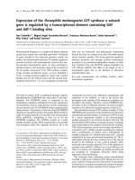
control, and reinforcement.
˗
Separation: geosynthetic can be used as a separator to isolate layers of soil that have
different characteristics (Figure 1.1a). For example, geotextile can be used between a
fine-grained subgrade and the granular layer below an embankment.
˗
Filtration: geosynthetic material can prevent soils but allow water to move from
migrating into the adjacent material, like a sand filter (Figure 1.1b).
˗
Drainage: geosynthetics can be used as a system of drains by allowing water to drain
from low permeability soils (Figure 1.1c).
2
1. Introduction
˗
Erosion control: geosynthetic act to limit the soil erosion caused by rainfall or surface
water because it prevents the movement of soil particles from the fluid flow (Figure
1.1d).
˗
Reinforcement: geosynthetics can be used as a reinforcement element to improve the
strength and mechanical properties of soils (Figure 1.1e). Geosynthetic-reinforced
soils include several products which are relatively soft structures made of fibers can
be produced as woven, non-woven or knitted, and geogrids, the more rigid appearance,
can be formed by cable knitting, coating or extrusion. Currently, design and
construction of geosynthetic-reinforced soils structures are commonly applied to many
geotechnical engineering projects by the basic principle is to increase the shear
strength of soils.
a
b
d
c
e
Figure 1.1. Geosynthetics functions (IGS, 2018a)
Moreover, geosynthetics are also used in other applications. They are used for asphalt
pavement reinforcement, flexible concrete formworks, and sandbags. The geosynthetic
materials can be used to limit the migration of fluid or to protect the surface of pavement
structures from cracking in airports or roadways.
Based on the method of manufacture, the main product categories of geosynthetic can be listed
as geotextiles, geogrids, geonets, geomembranes, geofoam, geocells, geocomposite, and
geosynthetic clay liners.
˗
Geotextiles: the oldest product of geosynthetics can be supplied in two primary types:
the woven and the nonwoven geotextiles differenced by the method of manufacture.
3