Optical Signal Processing Based on 4×4 Multimode Interference Structures
Bạn đang xem bản rút gọn của tài liệu. Xem và tải ngay bản đầy đủ của tài liệu tại đây (1.17 MB, 6 trang )
<span class='text_page_counter'>(1)</span><div class='page_container' data-page=1>
<b>Optical Signal Processing Based on 4×4 Multimode Interference </b>
<b>Structures </b>
<b>Duy-Tien Le1<sub>, Trung-Thanh Le</sub>1<sub>, and Laurence W. Cahill</sub>2*</b>
<i>1<sub>International School, Vietnam National University (VNU-IS), Hanoi, Vietnam </sub></i>
<i>2<sub>Department of Engineering, La Trobe University, Melbourne, Australia </sub></i>
<i>*<sub>Tel: (+613) 9479 3730, Fax: (+613)9471 0524, e-mail: </sub><sub></sub></i>
<b>ABSTRACT </b>
All-optical logic gates have attracted considerable attention over the past decade. They have found application as
adders, subtractors, header recognizers, parity checkers and in encryption systems. In this paper, we present
a new structure based on cascaded 4×4 and 2×2 multimode interference (MMI) couplers for implementing
optical XOR, XNOR, NAND and OR logic gates. The emphasis of the design is on optimising bandwidth and
fabrication tolerance. Such a design would be useful for optical label swapping and recognition in optical packet
switching networks. We use silicon on insulator (SOI) waveguides that are compatible with the CMOS
technology, for designing the whole device. The Beam Propagation Method (BPM) and the Eigenmode
Expansion Method (EEM) are used for numerical simulations. We show that the contrast ratios for logic 1 and
logic 0 for XOR, XNOR, NAND, and OR gates are from 18 dB to 28 dB for a bandwidth of 30nm, respectively.
A large fabrication tolerance of ±500 nm can be achieved by using this structure.
<b>Keywords: optical logic gate, multimode interference, silicon on insulator, silicon photonics, beam propagation </b>
method.
<b>1. INTRODUCTION</b>
All-optical logic gates have received considerable attention over the last ten years. Optical logic gates have many
possible applications in optical signal processing systems and optical switching networks. Examples of potential
applications include adders, subtractors, header recognizers, parity checkers, and encryption systems [1]. In
all-optical networks, there is a great need for implementing all-all-optical logic gates having small size, low power
consumption and high-speed [2, 3]. These requirements can be met by using photonic integrated circuits,
especially silicon photonics. In the literature, there are some other approaches for realizing optical logic gates
based on variety of material systems such as optical logic based on nonlinear materials [4, 5], Mach-Zehnder
interferometer with a nonlinear phase shifter [6-11], semiconductor optical amplifiers (SOAs)[12],
microelectromechanical systems (MEMS) [13], MMI based photonic crystal [14, 15], periodic waveguide [16],
plasmonic waveguide[17] and multimode interference waveguide [18]. These methods require high power and/or
complicated fabrication. Over the last few years, we have presented a general theory for implementing optical
signal processing based on MMI elements [19-22]. For further development, we have proposed 2×2, 3×3 and
5×5 MMI based structures for implementing many optical logic gates including NAND, OR, AND, NOT,
XNOR, and NOR gates [1].
In this study, we further develop a new scheme for realizing optical logic gates based on only one 4×4 MMI
cascaded with a 2×2 MMI coupler. The device has the advantage of ease of fabrication, large fabrication
tolerance, high contrast ratio and compatibility with system-on-a- chip configuration.
<b>2. THEORY</b>
Optical logic functions can be realized using the interference between two signals. The principle of interference
between two waves was first introduced by Young in the study of light [23]. If two signals having the same
polarization, the same normalized amplitude but different phases ϕ1 and ϕ2 respectively, interfere with each
other, the normalized power of the summed signal is expressed by [24]
2
1 2
cos [( ) / 2]
<i>P</i>∝ ϕ ϕ− (1)
The normalized power of the summed signal will become zero if the phases ϕ1 and ϕ2 satisfy the relation
1 2
ϕ ϕ− = π, 3π,…, (2n+1)π, where n is an integer. Note that MMI structures naturally rely on interference for
their operation. The operation of an optical MMI coupler is based on the self-imaging principle [25, 26].
Self-imaging is a property of a multimode waveguide whereby an input field is reproduced in single or multiple
images at periodic intervals along the propagation direction of the waveguide. We assume that the structure has
<i>N input and N output access waveguides, all of which are identical single mode waveguides with width Wa</i>.
The input and output waveguides are located at position <i>pi</i> [27], given by
1
( )
2 <i>MMI</i>
<i>i</i> <i>W</i>
<i>p</i> <i>i</i>
<i>N</i>
</div>
<span class='text_page_counter'>(2)</span><div class='page_container' data-page=2>
The electrical field inside the MMI coupler can be expressed by [28]
2
1
( , ) exp( ) exp( )sin( )
4
<i>M</i>
<i>m</i>
<i>m</i> <i>MMI</i>
<i>m</i> <i>m</i>
<i>E p z</i> <i>jkz</i> <i>E</i> <i>j</i> <i>z</i> <i>p</i>
<i>W</i>
p p
=
= −
Λ
∑
(3)where <i>i</i>= ÷1 <i>N, and N is the number of ports of MMI coupler. Therefore, optical logic gates can be realized by </i>
solely using an MMI coupler along with phase shifters. For optical logic gates based on the MMI principle,
information is encoded at the input and the output in amplitude or in phase. In this work, phase encoding of
information is used for input signals and amplitude encoding is used for output signals. We use the logic “1” is
represented by <sub>1</sub><i><sub>e and logic “0” is represented by </sub>j</i>0 <sub>0</sub><i><sub>e . To determine the logic level at the output of the </sub>j</i>0
device, the power in the output waveguide needs to be compared to a threshold value. This can be done
electronically by connecting output ports to a photo-detector and a decision circuit. Another approach is to use
an optical threshold device based on active MMI couplers instead of using an electronic threshold device [29].
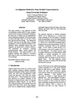
Figure 1(a) shows the proposed scheme for optical logic gate implementation based on 4×4 and 2×2 MMI
structures. By properly choosing the positions of input and output waveguides, the complex amplitude at output
port <i>y</i>2 can be expressed by
2 0.5( 1 2 3 4) 0.5( 1 4) 0.5( 2 3) ( , )2 3
<i>y</i> = <i>jx x</i>+ + <i>jx x</i>− = <i>jx x</i>− + <i>x</i> + <i>jx</i> = <i>f x x</i> (4)
where <i>x x</i>1, 4 are local oscillators and <i>x x</i>2, 3are input logic variables and <i>y</i>2 is the output logic variable. Here we
assume that the wavelength and polarization of the local oscillation signals and information signals are the same.
<i> (a) (b) W = 500 nm </i>
<i>Figure 1: (a) Proposed scheme for optical logic gates: (b) Field profile of the waveguide. </i>
In this study, we use the SOI waveguide with a width of 500 nm, height of 220 nm and slab height of 90 nm
for single mode operation. The optical mode of the waveguide simulated by the EEM method is shown
in Fig. 1(b). From eq. (4) we can achieve XOR, XNOR, OR and NAND logic gates by the following principles:
<b>(a) XOR gate: </b>
To realize the XOR logic gate, we use the local oscillation inputs /2
1 1 <i>j</i>
<i>x</i> <sub>=</sub> <i>e</i>p <sub> and </sub> 0
4 1 <i>j</i>
<i>x</i> = <i>e</i> and we assume that
a phase shifter of −p/ 2 is used at the input port <i>x</i>3. The input signal is encoded by the phase information. This
means that on input port <i>x</i>3, / 2p phase corresponds to logic 1 and −p/ 2corresponds to logic 0. For input port
2
<i>x</i> , 0-phase corresponds to logic 0 and p-phase corresponds to logic 1. As a result, the truth table for the XOR
gate is shown in Table 1.
<b>(b) XNOR gate: </b>
We use the local oscillation inputs /2
1 1 <i>j</i>
<i>x</i> <sub>=</sub> <i>e</i>p <sub> and </sub> 0
4 1 <i>j</i>
<i>x</i> = <i>e</i> and we assume that a phase shifter of / 2p is used
at the input port <i>x</i>3. For input port <i>x</i>3, a / 2p phase corresponds to logic 0 and −p/ 2corresponds to logic 1.
For input port <i>x</i>2, 0-phase corresponds to logic 0 and p-phase corresponds to logic 1. As a result, the truth table
for the XNOR gate is shown in Table 2.
<i>Table 1. Truth table of the XOR logic gate. </i>
Input logic Output logic
2
<i>x</i> (phase) <i>x</i>3<i> (phase) y</i>2<i> = f(x</i>2, <i>x</i>3)
0 (0) <sub>0 (</sub>−p <sub>/ 2</sub>) 0
0 (0) <sub>1 (</sub>p<sub>/ 2</sub>) 1
1 (p) 0 (−p / 2) 1
1 (p) <sub>1 (</sub>p<sub>/ 2</sub>) 0
<i>Table 2. Truth table of the XNOR logic gate. </i>
Input logic Output logic
2
<i>x</i> (phase) <i>x</i>3<i> (phase) y</i>2<i> = f(x</i>2, <i>x</i>3)
0 (0) <sub>0 (</sub>p<sub>/ 2</sub>) 1
0 (0) <sub>1 (-</sub>p <sub>/ 2</sub>) 0
1 (p) 0 (p/ 2) 0
1 (p) <sub>1 (-</sub>p <sub>/ 2</sub>) 1
</div>
<span class='text_page_counter'>(3)</span><div class='page_container' data-page=3>
<b>(d) NAND gate: </b>
We use the local oscillation inputs /2
1 1 <i>j</i>
<i>x</i> <sub>=</sub> <i>e</i>p <sub> and </sub> /2
4 1 <i>j</i>
<i>x</i> <sub>=</sub> <i>e</i>p <sub>. For input ports </sub>
2
<i>x</i> and <i>x</i>3, 0-phase corresponds
to logic 0 and p-phase corresponds to logic 1. The truth table for the NAND gate is shown in Table 4.
<i>Table 3. Truth table of the OR logic gate. </i>
Input logic Output logic
2
<i>x</i> (phase) <i>x</i>3<i> (phase) y</i>2 <i>= f(x</i>2, <i>x</i>3)
0 (0) 0 (0) 0
0 (0) 1 (p) 1
1 (p) 0 (0) 1
1 (p) 1 (p) 1
<i>Table 4. Truth table of the NAND logic gate. </i>
Input logic Output logic
2
<i>x</i> (phase) <i>x</i>3<i> (phase) y</i>2<i> = f(x</i>2, <i>x</i>3)
0 (0) 0 (0) 1
0 (0) 1 (p) 1
1 (p) 0 (0) 1
1 (p) 1 (p) 0
<b>3. SIMULATION RESULTS </b>
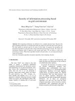
In this section, light propagation through the logic gates is investigated. The BPM method is used for the
simulations. Figure 2 shows the field distributions of the XOR logic gate at a wavelength of 1.55 µm for input
logic values of 00, 01, 10 and 11, respectively. The simulations show that there is good agreement with the
theoretical analysis given by Table 1.
(a) Input 00 (b) Input 01
(c) Input 10 (b) Input 11
<i>Figure 2. XOR gate with input signals 00, 01, 10, 11. </i>
Figure 3 shows the field distributions of the XNOR logic gate for input logic values of 00, 01, 10 and 11,
respectively. The simulations show that there is a good agreement with the theoretical results given by Table 2.
(a) Input 00 (b) Input 01
(c) Input 10 (b) Input 11
<i>Figure 3. XNOR gate with input signals 00, 01, 10, 11. </i>
</div>
<span class='text_page_counter'>(4)</span><div class='page_container' data-page=4>
(a) Input 00 (b) Input 01
(c) Input 10 (b) Input 11
<i>Figure 4. OR gate with input signals 00, 01, 10, 11. </i>
Figure 5 shows the field distributions of the NAND logic gate for input logic values of 00, 01, 10 and 11,
respectively. The simulations shows that there is good agreement with the theoretical analysis given by Table 4.
(a) Input 00 (b) Input 01
(c) Input 10 (b) Input 11
<i>Figure 5. OR gate with input signals 00, 01, 10, 11. </i>
For a compact device, we use a width of 6 àm for the 4ì4 MMI coupler. The normalized output powers at output
ports <i>y</i>3 and <i>y</i>4<i> for a signal at input port x</i>4 are shown in Fig. 6(a). The overall transmission of the structure
</div>
<span class='text_page_counter'>(5)</span><div class='page_container' data-page=5>
We evaluate the performance of the optical logic gates by using the contrast ratio (CR). For example, the optical
XOR gate, the CR is expressed by
logi 1
10
logi 0
10log ( <i>c</i> )(dB)
<i>c</i>
<i>P</i>
<i>CR</i>
<i>P</i>
= (5)
As a result, the CR for the XOR gate is shown in Fig. 7. It is shown that for a bandwidth of 30nm from 1530 nm
to 1560 nm, the CR varies from 18 dB to 28 dB.
<i>Figure 7: (a) Normalized output powers for logic 1 and 0;(b) Contrast ratio. </i>
Figure 8 shows the normalized output powers for a variation of the MMI length. We can see that for a fabrication
tolerance of ±500 nm, the variation in the normalized output powers of 0.02 can be achieved. This results in
a very large fabrication tolerance.
<i>Figure 8. Normalized output powers with different lengths of the 4×4 MMI coupler. </i>
<b>4. CONCLUSIONS </b>
</div>
<span class='text_page_counter'>(6)</span><div class='page_container' data-page=6>
<b>REFERENCES </b>
<i>[1] Trung-Thanh Le: Multimode Interference Structures for Photonic Signal Processing, LAP Lambert Academic </i>
Publishing, 2010.
<i>[2] A. D. McAulay: Optical Computer Architectures: The Application of Optical Concepts to Next Generation Computers, </i>
Wiley-Interscience, 1991.
<i>[3] J. Hardy and J. Shamir: Optics inspired logic architecture, Optics Express, vol. 15, pp. 150-165, 2007. </i>
<i>[4] D. Cotter, R. J. Manning, and K. J. Blow, et al.: Non-linear Optics for high-speed digital information processing, </i>
<i>Science, vol. 286, pp. 1523-1528, 1999. </i>
[5] Y. Wu, T. Shih and M. Chen: New all-optical logic gates based on the local nonlinear Mach-Zehnder interferometer,
<i>Optics Express, vol. 16, pp. 248-257, 2008. </i>
<i>[6] T. Yabu, M. Geshiro, and T. Kitamura, et al.: All-optical logic gates containing a two-mode nonlinear waveguide, </i>
<i>IEEE Journal of Quantum Electronics, vol. 38, 2002. </i>
<i>[7] G. Cancellieri, F. Chiaraluce, E. Gambi, et al.: Coupled-soliton photonic logic gates: Practical design procedures, </i>
<i>Journal of the Optical Society of America B, vol. 12, p. 1300, 1995. </i>
<i>[8] Y. H. Pramono, M. Geshiro, T. Kitamura, et al.: Optical logic OR, AND, NOT and NOR gates in waveguides </i>
<i>consisting of nonlinear material, IEICE Transactions on Electronics, vol. E83-C, p. 1755, 2000. </i>
<i>[9] W. Youfa and L. Jianhua: All-fiber logical devices based on the nonlinear directional coupler, IEEE Photonics </i>
<i>Technology Letters, vol. 11, pp. 72-74, 1999. </i>
[10] M. Zitelli, E. Fazio, and M. Bertolotti: All-optical NOR gate based on the interaction between cosine-shaped input
<i>beams of orthogonal polarization, Journal of the Optical Society of America B, vol. 16, p. 214, 1999. </i>
<i>[11] M. N. Islam: Ultrafast all-optical logic gates based on soliton trapping in fibers," Optics Letters, vol. 14, pp. 1257-1259. </i>
<i>[12] M. J. Connelly: Semiconductor Optical Amplifiers, Springer, 2002. </i>
[13] L. Y. Lin, E. L. Goldstein, and R. W. Tkach: Free-space micromachined optical switches with submilli-second
<i>switching time for large-scale optical crossconnects, IEEE Photonics Technology Letters, vol. 10, pp. 525-527, 1998. </i>
[14] E. Shaik and N. Rangaswamy: Multi-mode interference-based photonic crystal logic gates with simple structure and
<i>improved contrast ratio, Photonic Network Communications, vol. 34, pp. 140-148, 2017 2017. </i>
[15] Hussein M. E. Hussein, Tamer A. Ali, and N. H. Rafat: New designs of a complete set of photonic crystals logic gates,
<i>Optics Communications, vol. 411, pp. 175-181, 2018. </i>
<i>[16] Shunquan Zeng, Yao Zhang, Baojun Li, et al.: Ultrasmall optical logic gates based on silicon periodic dielectric </i>
<i>waveguides, Photonics and Nanostructures – Fundamentals and Applications, vol. 8, pp. 32-37, 2010. </i>
<i>[17] M. Ota, A. Sumimura, M. Fukuhara, et al.: Plasmonic-multimode-interference-based logic circuit with simple phase </i>
<i>adjustment, Scientific Reports, vol. 6, p. 24546, 2016. </i>
<i>[18] Z. Li, Z. Chen, and B. Li: Optical pulse controlled all-optical logic gates in SiGe/Si multimode interference, Optics </i>
<i>Express, vol. 13, pp. 1033-1038, 2005 </i>
<i>[19] L.W. Cahill and T. T. Le: MMI devices for photonic signal processing, in Proc. 9th International Conference on </i>
<i>Transparent Optical Networks (ICTON 2007), Rome, Italy, 1-5 July 2007 pp. 202 - 205. </i>
<i>[20] L. W. Cahill and T. T. Le: Photonic signal processing using MMI elements," in Proc. 10th International Conference on </i>
<i>Transparent Optical Networks (ICTON 2008), Athens, Greece, 2008. </i>
<i>[21] T.T. Le and L.W. Cahill: The modeling of MMI structures for signal processing applications, Integrated Optics: </i>
<i>Devices, Materials, and Technologies XII. Edited by C.M, Greiner and C. A. Waechter, Proc. SPIE, vol. 6896, </i>
pp. 68961G-68961G-7, 03/2008.
<i>[22] T. T. Le and L. Cahill: All-optical signal processing circuits using silicon waveguides, in Proc. 7th International </i>
<i>Conference on Broadband Communications and Biomedical Applications, Melbourne, Australia, 2011, pp. 167-172. </i>
<i>[23] F. Hunt, Origins in Acoustics: The Science of Sound from Antiquity to the Age of Newton, Yale University Press, 1978. </i>
<i>[24] L. Cahill and T. Le: The design of signal processing devices employing SOI MMI couplers, in Proc. SPIE Integrated </i>
<i>Optoelectronic Devices (OPTO 2009), Photonics West, San Jose, California, USA, Jan. 2009, paper 7220-2. </i>
[25] M. Bachmann, P. A. Besse, and H. Melchior: General self-imaging properties in N x N multimode interference
<i>couplers including phase relations, Applied Optics, vol. 33, p. 3905, 1994. </i>
[26] L.B. Soldano and E.C.M. Pennings: Optical multi-mode interference devices based on self-imaging: Principles and
<i>applications, IEEE Journal of Lightwave Technology, vol. 13, pp. 615-627, Apr. 1995. </i>
[27] Duy-Tien Le and Trung-Thanh Le: Coupled resonator induced transparency (CRIT) Based on interference effect in 4x4
<i>MMI coupler, International Journal of Computer Systems (IJCS), vol. 4, pp. 95-98, 2017. </i>
<i>[28] J.M. Heaton and R.M. Jenkins: General matrix theory of self-imaging in multimode interference(MMI) couplers, IEEE </i>
<i>Photonics Technology Letters, vol. 11, pp. 212-214, Feb. 1999. </i>
<i>[29] J. S. Rodgers, S. E. Ralph, and R. P. Kenan: Self guiding multimode interference threshold switch, Optics Letters, </i>
vol. 25, 2000.
<i>[30] M. J. Adams: Introduction to Optical Waveguide, John Wiley & Sons, 1981. </i>
<i>[31] N. Ahmed, T. Natarajan, and K. R. Rao: Discrete cosine transform, IEEE Transactions on Computers, vol. C-23, </i>
pp. 90-93, 1974.
<i>[32] R. Agarajan, C. H. Oyner, and R. P. Schneider, et al.: Large-scale photonic integrated circuits, IEEE Journal of </i>
</div>
<!--links-->