KRONE - Handbook - Structured Cabling System
Bạn đang xem bản rút gọn của tài liệu. Xem và tải ngay bản đầy đủ của tài liệu tại đây (524.06 KB, 12 trang )
Structured Cabling Systems
Delivering ZERO BIT ERRORS
TrueNet
™
SYSTEMS
HANDBOOK
TrueNet
™
SYSTEMS
HANDBOOK
2
TrueNet is the brain-child of two wiring
system technology leaders, Krone, Inc.,
and Prestolite Wire Corporation. These
distinguished companies have combined
resources to offer a structured cabling
system that delivers zero bit errors.
And this revolutionary new system is
fully-backed by a single-source, end-user
warranty. No other structured cabling
system supplier in the marketplace even
comes close to this level of performance
and throughput realization assurance.
KRONE, Inc.
Krone is an international leader in data and voice
connecting hardware technology — delivering its high
quality, high performance products to over 140 countries
around the globe.
Krone subscribes to a strict policy of continuous product
development and system improvement. And TrueNet is a
clear example of this aspect of the company’s conduct.
To achieve optimal data transmission throughput, all Krone
jacks have been engineered around what has been found
to be the critical electrical parameter — impedance.
Also, Krone is the originator of
silver-plated 45° IDC contact
technology. Silver provides a clear
advantage over traditional tin-plated
contacts, offering corrosion-free
connection over time. Even under
hostile environmental conditions,
such as extreme heat, cold, moisture
or exposure to salt, Krone contacts
maintain accurate, reliable voice
and data throughput.
This technology provides a far
more secure and corrosion-resistant
connection than all other IDC
terminations. The innovative
contact design also enables Krone
connectors to far exceed Category 5 requirements and
consistently out-perform the competition in both quality
and reliability. An additional Krone feature is
the insulation clamping ribs that firmly hold
the wire in place (and help maintain the
critical pair twists).
Krone unique 45°IDC contacts
ensure solid, gas-tight connections.
Krone HighBand technology.
The TrueNet
™
Dynamic
Equally impressive is Krone’s HighBand™ Termination
Block — a product that far surpasses the competition
and far exceeds Category 5 requirements. This Gigabit
Ethernet product is also extremely versatile — it can be
custom configured to meet a specific application, plus
complete patching and cross-connect options allow for
easy changes or testing.
Prestolite Wire
Since its founding in 1907, Prestolite has been a provider of
high quality wire and cable products for a diverse marketplace.
The company differentiates itself from its competition by
offering comprehensive transmission solutions.
TrueNet™ attests to the company’s interest in providing
far-reaching cabling solutions. In concert with Krone,
Prestolite looked at the entire structured cabling system —
while in operation — and then designed and developed
cabling products that ensured not just Category 5, 5e or 6
compliance, but uninterrupted data throughput (see above).
No other cabling system supplier has addressed the network
in this very real, very exhaustive way.
TrueNet cable is based upon a patent-pending technology
called TrueMatch™. This product design and manufacturing
innovation fine-tunes each cable pair to achieve an
operating impedance of 100±3 ohms. The cable is also
tuned to the various system components, such as connectors,
to achieve a 100±3 ohms impedance throughout the
cabling system — from NIC to server.
In addition to the
TrueNet products,
Prestolite provides a full
range of high quality
unshielded and shielded
twisted pair products for
both voice and data com-
munications. An extensive
line of singlemode and
multimode fiber optic
cables round out
Prestolite’s offering.
3
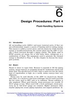
Compare the original signals transmitted by the
NIC cards (above, left) w ith the signals as they
appear at the far end (above, right) over a typical
Category 5 channel and a TrueNet
™
channel.
Only TrueNet protects the integrity of your data.
Patent-pending TrueMatch technology
individually tunes each twisted pair
for maximum performance.
For purposes of illustration,
the differences between the
twisted pairs are exaggerated.
Typical Category 5
TrueNet
™
Channel
Today’s high speed networks can bring tremendous
productivity advantages to your organization. But
getting the full rated performance out of even 100BASE-T
can be a real challenge. That’s because your structured
cabling system — the patch cables, the horizontal cable
and the connectors — can seriously degrade
your network’s performance.
Just because link lights are
‘on’ — verifying that nodes
are operating — doesn’t
mean that the network
is operating efficiently.
More than likely,
you are not getting
what you paid for —
a network that truly
approaches 100Mb/ s.
New Tests Reveal Key Determinants
Of Network Performance
Ethernet is based on standards developed by IEEE and
TIA/ EIA to ensure a nominal level of network compatibility
and performance. But new testing technology — which
measures a network while it’s in operation — shows that
simply adhering to these standards is not enough to ensure
network efficiency.
Our research with active network test equipment confirms
that mixing and matching components that individually
meet the TIA/ EIA standards does not ensure efficient
network performance. Optimal network throughput can
only be achieved with components that are 100±3 ohms
impedance-matched. And we have the test data to prove it!
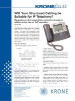
The graphics (below) demonstrate the impedance
match/ mismatch phenomenon. The mismatched channel
illustration depicts what can happen when a 107 ohm patch
cord is connected to a 97 ohm horizontal cable. Typically,
energy is reflected at the connection point causing signal
4
85Ω
Connection Point
115Ω
110Ω
105Ω
100Ω
95Ω
90Ω
Acceptable
Impedance Range
Ethernet Frame
Mismatched Channel
Key
Patch Cord
Horizontal Cable
NIC
Energy is reflected at
the mismatch, causing
some frame data to be
reflected and lost.
Damaged frames must
be re-transmitted, slowing
network performance.
Impedance mismatch
(107Ω to 97Ω) at
connection point.
Impedance Mismatched Channel
Connection Point
Matched components allow signal to travel
with minimum reflection and loss, minimizing
re-transmission and enhancing efficiency.
TrueNet™
Impedance Range
Ethernet Frame
TrueNet™ Channel
Key
Patch Cord
Horizontal Cable
NIC
85Ω
115Ω
110Ω
105Ω
100Ω
95Ω
90Ω
TrueNet™ Impedance Matched Channel
4 5 6 7 8 9 10 11 12
Impedance-
matched
components
allow your
data to travel
throughout
the netw ork
with minimal
reflection
and loss.
May Not Be OPERATING AS FAST AS YOU THINK
Your Network
degradation. This, of course, leads to data errors and data
re-transmissions — which can have a serious impact on
your network’s performance.
The TrueNet cabling system, depicted by the matched channel
illustration, shows how matched (100±3 ohm) components
allow the signal to travel without reflection and loss.
Data re-transmissions dramatically reduce the throughput
of the network (see table, right). As you can see, even a
1% rate of re-transmission can slow a 100Mb/ s Ethernet
network to just 20Mb/ s.
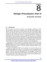
Putting It All Together
We can also “see” the effects of using mismatched vs.
matched channel componentry using an active 100BASE-T
network testing device (see above). The Category 5
compliant channel on the left shows the effects of
an impedance mismatch at the connection point of the
horizontal and patch cable. This mismatch results in wild
oscillations, or inconsistencies, in frequency. The graph
on the right shows the stable frequency trace of TrueNet
impedance-matched componentry — for consistent
signal transmission.
5
0% 100Mb/ s
1% 20Mb/ s
2% 4Mb/ s
3% 0.8Mb/ s
4% 0.16Mb/ s
5% 0.032Mb/ s
Maximum Percent Data
of Re-transmissions Rate
Effect of data
re-transmission
on network
throughput —
80% degradation from
only 1% re-transmission.
Impedance mismatch at a horizontal and patch cable
connection creates wide frequency variations.
Only TrueNet
™
protects the integrity of your data.
Ohms
0
79
30 60 90
87
95
103
111
119
Frequency (MHz)
Impedance vs. Frequency
140
1.0 50 100
Frequency (MHz)
1257525
121
112
131
102
93
Ohms
74
83
55
64
Pair 1
Pair 2
Pair 3
Pair 4
Impedance vs. Frequency