HVAC Systems Design Handbook part 6
Bạn đang xem bản rút gọn của tài liệu. Xem và tải ngay bản đầy đủ của tài liệu tại đây (751.83 KB, 46 trang )
Source: HVAC Systems Design Handbook
Chapter
6
Design Procedures: Part 4
Fluid-Handling Systems
6.1
Introduction
All air-handling units (AHUs) and many terminal units, if they are
not self-contained, require a source of heating and/or cooling energy.
This source is called a central plant, and the means by which thermal
energy is transferred between the central plant and the AHU is usually a fluid conveyed through a piping system. The fluids used in
HVAC practice are steam, hot or cold water, brine, refrigerant, or a
combination of these. The equipment used to generate the thermal
energy is described in Chap. 7. In this chapter we discuss the transport systems.
6.2
Steam
Steam is water in vapor form. Because it expands to fill the piping
system, steam requires no pumping except for condensate return and
boiler feed. The specific heat of water vapor is quite low, but the latent
heat of vaporization is high. As a result, steam conveys heat very
efficiently.
Steam may be used directly at the AHU (in steam-to-air, finnedtube coils), or a steam-to-water heat exchanger may be used to provide
the hot water used in AHU coils or in radiation. Steam radiation is
also employed. When used directly, steam pressures are usually 15
lb/in2 gauge or less. When used with a heat exchanger, steam pressures up to 100 lb/in2 gauge are common. Higher pressures allow
smaller piping but create piping expansion and support problems. In145
Downloaded from Digital Engineering Library @ McGraw-Hill (www.digitalengineeringlibrary.com)
Copyright © 2004 The McGraw-Hill Companies. All rights reserved.
Any use is subject to the Terms of Use as given at the website.
Design Procedures: Part 4
146
Chapter Six
dustrial plants often use high-pressure steam for heating as well as
for process purposes.
6.2.1
Steam properties
Table 6.1 shows thermodynamic properties of water at saturation temperatures and corresponding pressures from 0 to 250ЊF. Complete tables in the American Society of Mechanical Engineers (ASME) steam
tables1 cover a range from 32 to 700ЊF. Other tables cover superheated
steam. The ASHRAE Handbook Fundamentals2 extends the ‘‘at saturation’’ table down to Ϫ80ЊF.
The table indicates that there is a correspondence between saturation temperature and absolute pressure. Thus, the normal (sea-level)
boiling point of 212ЊF corresponds to the standard sea-level pressure
of 14.71 lb/in2. At higher altitudes (and lower atmosphere pressures),
the boiling temperature decreases until in Albuquerque, New Mexico,
or Denver, Colorado, 1 mi above sea level, it takes 4 or 5 min to boil
a 3-min egg.
The steam property of greatest interest to the HVAC designer is
enthalpy, particularly the enthalpy of evaporation, or the latent heat
of vaporization hfg. This is the amount of heat, in Btu per pound, which
TABLE 6.1
Thermodynamic Properties of Water at Saturation
SOURCE: Copyright 2001, American Society of Heating, Refrigerating and Air Conditioning Engineers, Inc., www.ashrae.org. Abstracted by permission from ASHRAE Handbook,
2001 Fundamentals, Chap. 6, Table 3.
Downloaded from Digital Engineering Library @ McGraw-Hill (www.digitalengineeringlibrary.com)
Copyright © 2004 The McGraw-Hill Companies. All rights reserved.
Any use is subject to the Terms of Use as given at the website.
Design Procedures: Part 4
Design Procedures: Part 4
147
must be added to change the state of the water from liquid to vapor
with no change in temperature. This same amount is removed and
used, in a heat exchanger, when steam is condensed. Note that while
liquid water has an enthalpy change of about 1 Btu/lb per degree of
temperature change and steam has much less than that, the changeof-state enthalpy is 970 Btu/lb at 212ЊF. This is what makes steam so
efficient as a conveyor of heat. In calculating the steam quantity
(pounds per hour) required for a specific application, use the latent
heat hfg.
Steam quality refers to the degree of saturation in a mixture of
steam and free water. As indicated in Table 6.1, there is a saturation
pressure (or ‘‘vapor’’ pressure) corresponding to each absolute temperature. When the pressure and temperature match, the steam is said
to be saturated, with a quality of 100 percent. When steam flows in a
piping system, there is always some heat loss through the pipe wall,
with a consequent reduction in temperature. If the steam was initially
saturated, some will condense into waterdroplets that will be carried
along with the flow. Then the steam quality will be less than 100
percent. Steam containing free water is wet steam. The free moisture
can cause problems in some types of equipment, such as turbines.
Steam lines must be sloped downward in the direction of flow, so that
condensed water can be carried along to a point where it can be extracted. When the steam temperature exceeds the saturation temperature, the steam is superheated. Superheated steam is useful where
free moisture is to be avoided, such as in some turbines.
6.2.2
Pressure reduction
When steam is distributed from a central plant, it may be desirable
to use higher pressures for distribution, resulting in smaller piping.
Then it is usually necessary to use pressure-reducing valves (PRVs) to
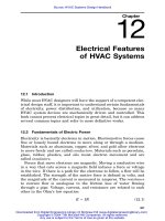
provide a suitable point-of-use pressure. A typical pressure-reducing
station is shown in Fig. 6.1. To provide better control, it is common
practice to use two PRVs in parallel, one sized for one-third and the
other sized for two-thirds of the load, respectively, and sequenced so
that the smaller valve opens first. This allows the larger valve to work
against smaller pressure differentials, which helps to avoid wire drawing of the valve seat at low loads. A manual bypass with a globe valve
is provided for emergency use. The PRV should have an internal or
external pilot, for accurate control of downstream pressure regardless
of upstream changes.
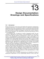
The maximum pressure drop through any steam PRV at the design
flow rate is about one-half of the entering pressure; more exactly, the
ratio of downstream to upstream pressure cannot be less than 0.53.
This is due to the physical laws governing flow of compressible fluids
Downloaded from Digital Engineering Library @ McGraw-Hill (www.digitalengineeringlibrary.com)
Copyright © 2004 The McGraw-Hill Companies. All rights reserved.
Any use is subject to the Terms of Use as given at the website.
Design Procedures: Part 4
148
Chapter Six
Figure 6.1 Pressure-reducing station.
through orifices. If greater pressure reductions are required, it is necessary to use two or more stages, as shown in Fig. 6.2, or to use an
oversized PRV, preferably sized by the manufacturer.
6.2.3
Steam condensate
Condensate is usually returned to the boiler for reuse. In small systems, this can sometimes be done by gravity. In most systems, pumping is required. The condensate flows by gravity to a collecting tank
from which it is pumped directly to the boiler or to a boiler feed system, as described in Chap. 7.
Condensate is basically distilled water. It often includes dissolved
carbon dioxide, making a weak but corrosive carbonic acid. The cor-
Figure 6.2 Two-stage pressure-reducing station.
Downloaded from Digital Engineering Library @ McGraw-Hill (www.digitalengineeringlibrary.com)
Copyright © 2004 The McGraw-Hill Companies. All rights reserved.
Any use is subject to the Terms of Use as given at the website.
Design Procedures: Part 4
Design Procedures: Part 4
149
rosive character of condensate must be addressed in condensate piping
material selection.
6.3
Water
Water is used extensively in modern cooling and heating practice because it is an effective heat transport medium and because it is considered simple to deal with. Because the water system can be essentially closed, there are fewer corrosion and water treatment problems
than with steam. Except in high-rise buildings, system static pressures are low and temperature changes are not severe, allowing the
use of low-cost materials and simple piping support systems. An exception is high-temperature hot water, discussed later in this chapter.
6.3.1
Water properties
Refer to Tables 6.1 and 6.2 for water properties over a wide range of
temperatures and corresponding pressures. The enthalpy of water
over this range changes at a rate of about 1 Btu/(lb ⅐ ЊF). For design
purposes, this value can be used without significant error. The density
of water varies from 62.3 lb/ft3 at 70ЊF to 60.1 lb/ft3 at 200ЊF. For
HVAC design purposes, the value of 62.3 lb/ft3 is commonly used; it
is sufficiently accurate over a range from 32 to 100ЊF but should be
compensated for at higher temperatures. Based on 7.5 gal/ft3, 1 gal
weighs about 8.3 lb. Then
1 Btu/(lb ⅐ ЊF) ϫ 8.3 lb/gal ϫ 60 min/h
ϭ 500 Btu/[h ⅐ (gal/min) ⅐ ЊF]
(6.1)
which is a constant commonly used in calculating water flow quantities.
To determine the water quantity required to serve a given load,
divide the load, in Btu per hour, by 500 and by the desired water
temperature drop or rise in degrees Fahrenheit. Typical numbers are
8, 10, and 20ЊF for cooling (resulting in a divisor of 4000, 5000, and
10,000, respectively) and 20 to 40ЊF for heating (a divisor of 10,000 to
20,000).
Another measure of water quantity is gallons per minute per tonhour of refrigeration. Because 1 ton ⅐ h equals 12,000 Btu/h, a 10ЊF
rise in the chilled water temperature works out to 2.4 gal/(min Ϫ ton).
An 8ЊF rise requires 3 gal/(min Ϫ ton), and a 20ЊF rise is 1.2 gal/
(min Ϫ ton). On the condensing water side, it is assumed that heat
rejection in a vapor compression machine is approximately 15,000
Btu/(ton Ϫ h) and a 10ЊF rise requires 3 gal/(min Ϫ ton Ϫ h). The
Downloaded from Digital Engineering Library @ McGraw-Hill (www.digitalengineeringlibrary.com)
Copyright © 2004 The McGraw-Hill Companies. All rights reserved.
Any use is subject to the Terms of Use as given at the website.
SOURCE: Reprinted by permission from Thermodynamic Properties of Steam, J. H. Keenan and F. G.
Keyes, published by John Wiley and Sons, Inc., 1936 edition. Subsequent editions have equivalent data.
TABLE 6.2
Properties of Water, 212 to 400؇F
Design Procedures: Part 4
150
Downloaded from Digital Engineering Library @ McGraw-Hill (www.digitalengineeringlibrary.com)
Copyright © 2004 The McGraw-Hill Companies. All rights reserved.
Any use is subject to the Terms of Use as given at the website.
Design Procedures: Part 4
Design Procedures: Part 4
151
actual heat rejection will vary with the refrigeration system efficiency
and will usually be somewhat less than 15,000 Btu/(ton Ϫ h), except
that for absorption refrigeration, rejection will be 20,000 to 30,000
Btu/(ton Ϫ h).
6.4
High-Temperature Water
High-temperature water (HTW) systems operate with supply water
temperatures over 350ЊF and with a pressure rating of 300 to 350 lb/
in2 gauge (psig). Maximum temperatures are about 400ЊF in order to
stay within the 300 lb/in2 gauge limit on pipe and fittings. Mediumtemperature systems operate with supply water temperatures between 250 and 350ЊF, which allows the use of 150 lb/in2 gauge rating
on piping systems. Table 6.2 lists properties of water at temperatures
up to 400ЊF.
Systems must be kept tight because water at these temperatures
will flash instantly to steam at any leak. Large temperature drops at
heat exchangers are typical—150 to 200ЊF is normal. The system must
be carefully pressurized to above the saturation pressure corresponding to the water temperature, to prevent the water from flashing into
steam.
Heat exchangers are used to provide lower-temperature hot water
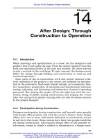
or steam for HVAC use. HTW may be used directly for generation of
domestic hot water. Most jurisdictions require double-wall heat exchangers to guarantee protection from tube failure and crosscontamination. It is common to place user equipment in series, taking
part of the HTW temperature drop through each device (Fig. 6.3).
Steam generation, at other than low pressure (less than 15 psig), is
not a good load for an HTW system. It is desirable to maximize the
temperature difference between the HTW supply and return, so that
the central plant may operate more efficiently.
6.5 Secondary Coolants
(Brines and Glycols)
Brine is a mixture of water and any salt, with the purpose of lowering
the freezing point of the mixture. In HVAC practice, the term is also
applied to mixtures of water and one of the glycols. Brines are used
as heat transfer fluids when near- or subfreezing temperatures are
encountered. Ice-making systems for thermal storage often use a brine
solution as part of the scheme. Brines may be used directly in cooling
coils of air-handling units or, through heat exchangers, may be used
to provide chilled water. Brines are also commonly used in runaround
Downloaded from Digital Engineering Library @ McGraw-Hill (www.digitalengineeringlibrary.com)
Copyright © 2004 The McGraw-Hill Companies. All rights reserved.
Any use is subject to the Terms of Use as given at the website.
Design Procedures: Part 4
152
Chapter Six
Figure 6.3 HTW end use, with cascading.
heat reclaim systems (see Chap. 7). Heating systems exposed to subfreezing air may use a glycol solution as a circulating medium.
6.5.1
Properties of secondary coolants
Calcium and sodium chloride solutions in water have been the most
common brines. Properties of pure brines are shown in Tables 6.3 and
6.4. For commercial-grade brines, use the formulas in the footnotes to
the tables. Note particularly that the specific heat decreases as the
percentage of the salt increases. Thus, a 25% solution of calcium chlo-
Downloaded from Digital Engineering Library @ McGraw-Hill (www.digitalengineeringlibrary.com)
Copyright © 2004 The McGraw-Hill Companies. All rights reserved.
Any use is subject to the Terms of Use as given at the website.
Properties of Pure Calcium Chloride Brine
*Mass of water per unit volume ϭ Brine mass minus CaCl2 mass.
†Specific gravity is solution at 60ЊF referred to water at 60ЊF.
SOURCE: Copyright 2001, American Society of Heating, Refrigerating and Air Conditioning Engineers,
Inc., www.ashrae.org. Reprinted by permission from ASHRAE Handbook, 2001 Fundamentals, Chap.
21, Table 1.
TABLE 6.3
Design Procedures: Part 4
153
Downloaded from Digital Engineering Library @ McGraw-Hill (www.digitalengineeringlibrary.com)
Copyright © 2004 The McGraw-Hill Companies. All rights reserved.
Any use is subject to the Terms of Use as given at the website.
Properties of Pure Sodium Chloride Brine
*Mass of commercial NaCl required ϭ (mass of pure NaCl required) / (% purity).
†Mass of water per unit volume ϭ brine mass minus NaCl mass.
‡Specific gravity is solution at 59ЊF referred to water at 39ЊF.
SOURCE: Copyright 2001, American Society of Heating, Refrigerating and Air Conditioning Engineers,
Inc., www.ashrae.org. Reprinted by permission from ASHRAE Handbook, 1989 Fundamentals, Chap.
21, Table 2.
TABLE 6.4
Design Procedures: Part 4
154
Downloaded from Digital Engineering Library @ McGraw-Hill (www.digitalengineeringlibrary.com)
Copyright © 2004 The McGraw-Hill Companies. All rights reserved.
Any use is subject to the Terms of Use as given at the website.
Design Procedures: Part 4
Design Procedures: Part 4
155
ride will lower the freezing point of the mixture to Ϫ21ЊF and will
decrease the specific heat to 0.689 Btu/(lb ⅐ ЊF). This means that the
solution will transport only about two-thirds of the heat transported
by pure water at the same mass flow rate and temperature difference.
The volumetric flow rate is partially offset by the increased mass of
the mixture in pounds per gallon.
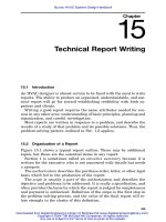
Note that the viscosity of the brine increases (Fig. 6.4) while the
thermal conductivity decreases (Fig. 6.5) as the percentage of salt
increases. Compared to pure water, this results in a higher pumping
head and lower heat transfer rate. These brines are less effective than
water as a heat-conveying medium. The tables indicate a percentage
solution at which a minimum freezing temperature is obtained. This
is the eutectic point. Brine solutions are corrosive, particularly when
exposed to air or carbon dioxide. Inhibitors are recommended. Chro-
Figure 6.4 Viscosity of calcium chloride brine. (SOURCE: Copyright 2001, American Society of Heating, Refrigerating and Air Conditioning Engineers, Inc., www.ashrae.org.
Reprinted by permission from ASHRAE Handbook, 2001 Fundamentals, Chap. 21, Fig.
3.)
Downloaded from Digital Engineering Library @ McGraw-Hill (www.digitalengineeringlibrary.com)
Copyright © 2004 The McGraw-Hill Companies. All rights reserved.
Any use is subject to the Terms of Use as given at the website.
Design Procedures: Part 4
156
Chapter Six
Figure 6.5 Thermal conductivity of calcium chloride brine. (SOURCE: Copyright 2001,
American Society of Heating, Refrigerating and Air Conditioning Engineers, Inc.,
www.ashrae.org. Reprinted by permission from ASHRAE Handbook, 2001 Fundamentals, Chap. 21, Fig. 4.)
mate solutions are now typically prohibited. Other chemicals, such as
sodium nitrite or sodium borate, may be used. A qualified water treatment expert should be consulted.
Solutions of ethylene glycol or propylene glycol in water are used
extensively. With proper inhibitors to prevent corrosion, these solutions can lower the mixture’s freezing point to well below 0ЊF (Fig.
6.6). As with the salt solutions, the thermal conductivity and specific
heat of the mixture decrease and the viscosity increases with an increase in the percentage of glycol. Inhibitors must be checked and
maintained periodically. While both HVAC and automobile glycols are
formulated from the same base compounds, the additives are different,
and automobile glycols are typically not suited for HVAC use.
Downloaded from Digital Engineering Library @ McGraw-Hill (www.digitalengineeringlibrary.com)
Copyright © 2004 The McGraw-Hill Companies. All rights reserved.
Any use is subject to the Terms of Use as given at the website.
Design Procedures: Part 4
Design Procedures: Part 4
157
Figure 6.6 Properties of sodium chloride brine solutions, and freezing points of aqueous
solutions of ethylene glycol and propylene glycol. (SOURCE: Copyright 2001, American
Society of Heating, Refrigerating and Air Conditioning Engineers, Inc., www.ashrae.org.
Reprinted by permission from ASHRAE Handbook, 2001 Fundamentals, Chap. 21, Figs.
5, 6, 7, 8.)
Common refrigerants may also be used as a secondary coolant. That
is, liquid refrigerant may be pumped through distribution piping. Refrigerants have the advantages of low freezing points and low viscosity, but also have low specific heats.
Downloaded from Digital Engineering Library @ McGraw-Hill (www.digitalengineeringlibrary.com)
Copyright © 2004 The McGraw-Hill Companies. All rights reserved.
Any use is subject to the Terms of Use as given at the website.
Design Procedures: Part 4
158
6.6
Chapter Six
Piping Systems
A piping system is the means by which the thermal energy of a fluid
is transported from one place to another. The type of fluid and its
temperature and pressure influence and limit the choice of piping materials. Most systems are closed; i.e., the fluid is continually recirculated and no makeup water is required except to replace that lost due
to leaks. Steam systems are partly to completely open—as when the
steam is used for a process or humidification—and require continuous
makeup water. Cooling-tower water systems are open and need
makeup water to replace the water evaporated in the tower.
Closed systems require some means of compensating for the changes
in volume of the fluid due to temperature changes. Expansion (compression) tanks are used.
Piping must be properly supported, with compensation for expansion due to temperature changes and anchors to prevent undesired
movement.
6.6.1
Piping materials
By far the most common material used in HVAC piping systems is
black steel (low-carbon steel). Table 6.5 covers dimensional data for
steel pipe. Pressure ratings vary with the pipe size (greater for smaller
pipes), but in general, standard-weight pipe can be used for working
pressures up to 300 lb/in2 gauge, extra-strong pipe to 450 lb/in2 gauge,
and double-extra-strong pipe to 1000 lb/in2 gauge or more. Pipes of
14-in and larger outside diameter (OD) are made with thinner walls
for the lower pressures which are often acceptable, as well as with
thicker walls for higher pressures.
Another standard defines pipe sized by schedule number. In this
system, schedule 40 is the same as standard weight, and schedule 80
is the same as extra-strong, up to 6 in in size. Sizes of 8, 10, and 12
in standard weight are the same as schedule 30.
Black steel is often preferred because it is strong, is readily available, can be used over a wide range of temperatures and pressures,
and is easy to assemble and join by several common methods. If proper
inhibitors are used in the steam, water, and brine, black steel corrodes
very little; and in closed systems it will tend to stabilize in a neutral,
noncorrosive state. Unfortunately, very few systems remain completely closed for very long, so at least some water treatment is necessary.
Another popular piping material for HVAC systems is copper, usually in tubing form. Copper pipe has the same outside diameter as
steel pipe, with slightly thinner walls. Dimensions of copper tubing
Downloaded from Digital Engineering Library @ McGraw-Hill (www.digitalengineeringlibrary.com)
Copyright © 2004 The McGraw-Hill Companies. All rights reserved.
Any use is subject to the Terms of Use as given at the website.
Steel Pipe Dimensions and Weights
*Volume in cubic feet of water per foot of pipe length, standard weight. Also 8-, 10-, and 12-in pipe is
made with thinner walls, but these are nonstandard. Intermediate sizes such as 31⁄2 in are also made,
but seldom used. And 1⁄8 and 3⁄8 in are also made. Larger sizes, 14 to 30 in, have nominal size equal to
outside diameter but are not part of this standard.
12
12
14
34
12
14
TABLE 6.5
Design Procedures: Part 4
159
Downloaded from Digital Engineering Library @ McGraw-Hill (www.digitalengineeringlibrary.com)
Copyright © 2004 The McGraw-Hill Companies. All rights reserved.
Any use is subject to the Terms of Use as given at the website.
Design Procedures: Part 4
160
Chapter Six
are shown in Table 6.6. Type L is most commonly used and is suitable
for pressures of up to about 250 to 300 lb/in2 gauge.
Other materials include fiberglass-reinforced plastic (FRP), ultrahigh molecular weight polyethylene (UHPE), polypropylene (PP) polybutylene, (PB), polyvinyl chloride (PVC), and chlorinated polyvinyl
chloride (CPVC). These have excellent corrosion resistance and low
flow resistance, but have lower pressure and temperature ratings than
steel or copper. Complete data on these materials are available from
the manufacturers. PVC is often used for equipment drain lines.
Galvanized-steel piping is used occasionally. The dimensions are the
same as for black-steel pipe.
Occasionally cast iron, but more often ductile iron, has some HVAC
applications. Ductile iron can be grooved to accept gasketed iron couplings.
Cast-iron piping is seldom used in sizes less than 4 in, although
cast-iron fittings are available down to 1-in size. Wrought-iron piping
has been used extensively in the past for steam condensate, but it is
seldom used anymore because of the extra cost.
Some regions of the country have a well-developed stainless steel
market. On a local basis, stainless steel piping may be found to be
cost competitive with other piping materials.
6.6.2
Pipe fittings
Pipe fittings include elbows, tees, wyes, couplings, unions, reducers,
plugs, caps, and bushings. Elbows may be 45Њ, 90Њ, or even 180Њ, re-
TABLE 6.6
Copper Tubing Dimensions (in inches)
38
12
34
14
12
12
12
Note: Tubing is available up to 8 in.
Downloaded from Digital Engineering Library @ McGraw-Hill (www.digitalengineeringlibrary.com)
Copyright © 2004 The McGraw-Hill Companies. All rights reserved.
Any use is subject to the Terms of Use as given at the website.
Design Procedures: Part 4
Design Procedures: Part 4
161
ducing or nonreducing, with short or long radius. Tees and wyes may
also be reducing types. Special fittings are available to prevent electrolytic corrosion when dissimilar piping materials are joined. A standard manufacturer’s catalog can be consulted for dimensions and
types of fittings.
6.6.3
Joining methods
Steel pipe joints may be welded, threaded, grooved, or flanged. Welding is typical on piping 3 in in diameter and larger and should be done
in accordance with ASME power piping standards,3 using certified
welders. The grooved joint is made by using a gasketed clamp which
locks into grooves cut or rolled near the end of the pipe section or
fitting. Gasket materials must be suitable for the temperature, pressure, and the nature of the fluid handled.
Copper pipe joints may be brazed, threaded, grooved, or flanged.
Copper tubing is joined by soldering or brazing or by the use of compression or grooved fittings.
FRP and PVC piping are usually joined by use of solvent cement.
Flanged joints are also employed. Some other plastics are joined by
heat fusion.
All piping systems must be provided with unions (screwed or
flanged) at connections to equipment and valves.
6.6.4 Supports, anchors, guides,
and expansion
Spacing of pipe supports is a function of pipe size and material. The
principal objectives are to avoid sagging and to maintain a uniform
slope to allow good drainage. Steam lines must be trapped at low
points to provide for removal of condensate. There are many different
support systems available; a complete discussion is beyond the scope
of this book.
The length of all piping will change as the temperature of the fluid
changes. With steam or high-temperature water, the changes can be
great. For example, steel has a linear coefficient of expansion of
0.00000633 ft/ft per degree Fahrenheit. If a steel pipeline 100 ft long
is installed in an ambient of 50ЊF and is later filled with saturated
steam at 15 lb/in2 gauge (250ЊF), the pipe length will increase about
1.52 in. If left unrestrained, the pipe may move in unacceptable ways.
If the pipe is restrained without provision for expansion, large forces
will be developed and either the pipe or the restraints may break. The
expansion must be compensated by means of expansion joints, loops,
or elbows.
Downloaded from Digital Engineering Library @ McGraw-Hill (www.digitalengineeringlibrary.com)
Copyright © 2004 The McGraw-Hill Companies. All rights reserved.
Any use is subject to the Terms of Use as given at the website.
Design Procedures: Part 4
162
Chapter Six
Figure 6.7 Expansion joint, bellows type. Left: plain; right: with equalizing rings. (Cour-
tesy of Adsco Manufacturing Corp.)
Expansion joints may be of the bellows (Fig. 6.7), slide, or flex-joint
type. Joints are simpler than loops, but slide joints may develop leaks
over time unless packing is maintained or replaced. Bellows joints
need no packing but may eventually fail due to fatigue. Expansion
may also be controlled by means of loops or elbows. Figure 6.8 shows
a simple piping system with an expansion loop and expansion elbow.
The design provides for flexibility so that the pipe can bend without
exceeding the allowable stress of the pipe material. Information on
the design of expansion loops and elbows can be found in many references (see Ref. 4) as well as from some pipe fitting manufacturers.
Note that using loops, offsets, and elbows to compensate for expansion and contraction results in a system with little required maintenance. Ball joints and slip joints have packing which must be maintained. Bellows joints tend to work harden over time.
For the expansion to be properly controlled, it is necessary to provide a point of reference, with no movement. This is called an anchor,
and the pipe must be fastened at this point strongly enough to resist
the forces generated by expansion. Failure of an anchor can be dis-
Figure 6.8 Expansion loop and expansion elbow.
Downloaded from Digital Engineering Library @ McGraw-Hill (www.digitalengineeringlibrary.com)
Copyright © 2004 The McGraw-Hill Companies. All rights reserved.
Any use is subject to the Terms of Use as given at the website.
Design Procedures: Part 4
Design Procedures: Part 4
163
astrous. In addition, guides must be provided to prevent unwanted
lateral movement in the pipeline. A guide restrains the pipe laterally
while allowing it to move lengthwise. The pipe must be free to move
on other, intermediate supports.
6.6.5
Valves
A valve is a device for controlling the flow of fluid in a pipeline. Control
may mean limiting or throttling flow, preventing backflow, or completely stopping flow. Automatic control valves are discussed in Chap.
8. Manually operated valves are discussed here.
There are a great many types and configurations of manual valves.
They can be grouped into a few general classes. Stop valves are used
for shutoff of flow. The primary reason is to allow isolation of equipment or sections of piping for repair or replacement. Throttling valves
can be adjusted to control flow quantities within limits which depend
on the system pressure variations. Backflow prevention valves, including check valves, are used to prevent flow in the wrong direction. Reverse flow may occur as a result of pressure changes and may degrade
system performance or may even be dangerous. Pressure-reducing
valves provide control of downstream pressure regardless of upstream
pressure variations, as long as upstream pressure exceeds downstream pressure. Pressure relief valves are safety devices which open
to relieve excessive pressures which might damage the system.
Traditionally, the most common stop valve has been the gate valve.
In the full-open position, the gate is out of the way and resistance to
flow is minimal. In the fully closed position, the gate seats tightly and
flow is effectively stopped. The gate valve is not a good throttling device. Gate valves are made in many sizes, configurations, and materials to handle almost any fluid or pressure.
In larger piping over 3 or 4 in, it may be less expensive to use a
butterfly valve. Butterfly valves are made in flange, wafer, or tapped
lug configuration. Do not use a wafer valve for dead-end service because it is held in place by clamping between the adjoining pipes. The
tapped lug body works as a flange union joint and can be used for
dead-end service. Butterfly valves are available in a more limited
range of pressure ratings and materials compared to gate valves.
For throttling control, the globe-type valve is often recommended.
Globe valves are made in many configurations, but all have a shaped
plug, such that gradual throttling can be accurately accomplished.
Many different sizes, materials, and pressure ratings are available.
A needle valve is similar in principle to a globe valve, but with a
needlelike plug. Needle valves are used mostly in small sizes for finetuning very small flows.
Downloaded from Digital Engineering Library @ McGraw-Hill (www.digitalengineeringlibrary.com)
Copyright © 2004 The McGraw-Hill Companies. All rights reserved.
Any use is subject to the Terms of Use as given at the website.
Design Procedures: Part 4
164
Chapter Six
A plug valve has a cylindrical slotted plug, frequently tapered,
which fits into the valve body tightly enough to prevent leakage. When
it is rotated so that the slot is aligned with the body ports, flow is
unimpeded. At right angles, flow is stopped. By rotating the plug to
an intermediate position, flow can be modulated. Plug valves are commonly used for ‘‘balancing’’ system flows, and some models have a
memory marker so that the valve can be used for shutoff and later
returned to the proper balance point.
The ball valve has gained great popularity in recent years. A ball
valve is similar to a plug valve but has a spherical plug with a round
hole drilled through the center, mounted in the valve body. Ball valves
have become the valve of choice over gate and globe valves in many
applications for reasons of cost and performance.
Backflow prevention valves are usually called check valves and come
in several types. The most common is the swing check. A flapper
swings open to allow flow in one direction but closes if flow is reversed.
This valve must be mounted so that gravity will assist in closing the
flapper. A spring-loaded check valve includes a spring to assist in closing the flapper; consequently it has a higher resistance to flow. A lift
check is arranged so that the flapper lifts off the seat to allow flow.
A pressure-reducing valve is an automatic control valve, usually a
globe type with a diaphragm operator which acts to modulate flow
through the valve to maintain a specified downstream pressure. For
compressible fluids such as steam, air, or gas, maximum flow through
the valve occurs at a ratio of downstream pressure to upstream pressure which is the critical pressure drop for the fluid, that is, 0.53 for
steam. Thus, if a greater than 50 percent reduction is required, it is
best to use two or three stages of pressure reduction for good control.
6.6.6
Pipe sizing
The principal criteria for sizing piping systems to serve a given flow
rate are velocity in feet per second, and pressure drop in feet of water
or pounds per square inch per 100 ft of pipe. The velocity is important
because the turbulence due to velocity causes noise, and the noise due
to high velocities may be unacceptable. The pipe may erode in turbulent high-velocity regions. The pressure drop in pumped systems
becomes part of the pump head and is, therefore, a contributor to operating cost. The higher first cost of larger piping must be balanced
against the increased operating cost of smaller piping.
Each design office has its target values of velocity and pressure drop
for water, usually in the range of 3 to 4 ft/100 ft and 6 to 8 ft/s for
large pipe to as low as 2 ft/s in small pipe. It will be found that the
pressure-drop limit governs in small pipe and the velocity limit governs in larger pipe.
Downloaded from Digital Engineering Library @ McGraw-Hill (www.digitalengineeringlibrary.com)
Copyright © 2004 The McGraw-Hill Companies. All rights reserved.
Any use is subject to the Terms of Use as given at the website.
Design Procedures: Part 4
Design Procedures: Part 4
165
Figure 6.9 shows flow versus head loss (pressure drop per 100 ft)
and velocity in schedule 40 steel pipe. This is for water at 60ЊF, but
the small error for warmer water gives conservative results. Figure
6.10 covers similar data for copper tubing. Data for plastic and PVC
piping are available from the manufacturers. Reference 6 is an excellent resource for pipe sizing data.
Pressure losses in fittings—tees, elbows, valves—are allowed for on
the basis of size and velocity, by using ‘‘equivalent length’’ values
which have been determined empirically. Table 6.7 lists equivalent
lengths for 90Њ elbows. Table 6.8 shows multipliers for Table 6.7 for
various other fittings. A rule of thumb which is frequently used is to
double the measured length of the piping system to allow for fittings.
This will not be satisfactory for systems with a high fittings-to-length
ratio, and in any case, it should be used only for preliminary estimates.
Steam line sizing is based on flow rate (pounds per hour) at a specified pressure and pressure drop. Figure 6.11 is a graph of flow rate
in pounds per hour versus pressure drop in pounds per square inch
per 100 ft and velocity in feet per minute. The figure is based on steam
at 0 lb/in2 gauge. The allowable pressure drop depends on the initial
pressure and the acceptable pressure at the end of the system. For 15
lb/in2 steam, typical pressure drops are in the range of 0.5 to 0.7 lb/
in2 per 100 ft. The maximum velocity should not exceed 10,000 ft/min
in large pipes (10 to 12 in), dropping to 2000 ft/min in 2-in and smaller
lines. This follows the old rule of thumb that ‘‘steam velocity in
thousands should not exceed the pipe diameter in inches.’’ Figure 6.12
provides velocity correction factors for pressures other than zero.
Condensate return lines, for gravity flow, can be sized by using Table
6.9. Wet return lines include no vapor. Dry lines include both steam
and liquid—this is most common—and vacuum refers to a return line
going to a vacuum pump and thus at a pressure below atmospheric.
Return lines must slope downward in the direction of flow.
6.6.7
Insulation
Pipe insulation is required whenever the temperature of the fluid in
the pipe is significantly different from the ambient temperature
around the pipe. This covers most heating and cooling applications.
An exception is condensate return piping which may be left uninsulated to allow any flash steam to condense. In such a case, vagrant
heat should be determined not to be a problem.
The required thermal resistance of the insulation is determined
from applicable energy or building codes, the insulation manufacturer’s recommendations, and calculations based on acceptable energy
losses in the piping system.
Downloaded from Digital Engineering Library @ McGraw-Hill (www.digitalengineeringlibrary.com)
Copyright © 2004 The McGraw-Hill Companies. All rights reserved.
Any use is subject to the Terms of Use as given at the website.
Figure 6.9 Friction loss for water in commercial steel pipe (schedule 40). (SOURCE: Copyright 2001,
American Society of Heating, Refrigerating and Air Conditioning Engineers, Inc., www.ashrae.org.
Reprinted by permission from ASHRAE Handbook, 2001 Fundamentals, Chap. 35, Fig. 1.)
Design Procedures: Part 4
166
Downloaded from Digital Engineering Library @ McGraw-Hill (www.digitalengineeringlibrary.com)
Copyright © 2004 The McGraw-Hill Companies. All rights reserved.
Any use is subject to the Terms of Use as given at the website.
Design Procedures: Part 4
Design Procedures: Part 4
167
Figure 6.10 Friction loss for water in copper tubing (types K, L, M). (SOURCE: Copyright
2001, American Society of Heating, Refrigerating and Air Conditioning Engineers, Inc.,
www.ashrae.org. Reprinted by permission from ASHRAE Handbook, 2001 Fundamentals, Chap. 35, Fig. 2.)
Piping insulation is usually ‘‘preformed’’ to snap readily in place
around the pipe. A protective jacket is required, usually canvas on hot
lines and a vapor barrier type on cold lines. The vapor barrier specification must include a mastic seal at all joints and edges and should
prohibit the use of staples. In areas where the pipe is exposed to damage, a metal or plastic jacket may be specified, including preformed
jacket sections for fittings and valves. Insulation should be verified as
acceptable for the application. Materials such as fiberglass, calcium
silicate, foamed glass, and foamed plastic are all available.
6.6.8 Distribution piping configurations
for water
Three basic system configurations are used: out-and-back, reversereturn, and loop.
The out-and-back system (Fig. 6.13) is common in large campus systems. The supply and return mains run in parallel from the central
plant to the points of use, with flow in opposite directions and with
equal reduction in size as flow rates reduce. This means that the point
with the lowest pressure difference from supply to return is at the end
of the main, as shown on the pressure profile (Fig. 6.14). Then the
branches nearest the central plant may require extra pressure reduction by means of balancing valves.
The reverse-return system (Fig. 6.15) is designed to provide pressure differences from supply to return which are similar at all
Downloaded from Digital Engineering Library @ McGraw-Hill (www.digitalengineeringlibrary.com)
Copyright © 2004 The McGraw-Hill Companies. All rights reserved.
Any use is subject to the Terms of Use as given at the website.
12
34
14
12
Equivalent Length of Pipe for 90؇ Elbows, ft
12
12
SOURCE: Copyright 2001, American Society of Heating, Refrigerating and Air Conditioning Engineers,
Inc., www.ashrae.org. Abstracted by permission from ASHRAE Handbook, 2001 Fundamentals, Chap.
35, Table 8.
TABLE 6.7
Design Procedures: Part 4
168
Downloaded from Digital Engineering Library @ McGraw-Hill (www.digitalengineeringlibrary.com)
Copyright © 2004 The McGraw-Hill Companies. All rights reserved.
Any use is subject to the Terms of Use as given at the website.
Design Procedures: Part 4
Design Procedures: Part 4
TABLE 6.8
169
Iron and Copper Elbow Equivalents
See Table 6.7 for equivalent length of one elbow.
SOURCE: Copyright 2001, American Society of Heating, Refrigerating and Air Conditioning Engineers,
Inc., www.ashrae.org. Reprinted by permission from
ASHRAE Handbook, 2001 Fundamentals, Chap. 35,
Table 9.
branches, as shown in the pressure profile in Fig. 6.16, so that the
minimum amount of balancing is required. This is accomplished by
beginning the return main at the location of the first takeoff from the
supply and continuing the return main parallel to the supply main
with flow in both pipes in the same direction. The return main increases in size as the supply main decreases. Finally, the return main
goes back to the central plant.
The loop system (Figs. 6.17 and 6.18) consists of supply and return
mains which are closed loops, with a constant pipe size. The loops are
fed at one point from the central plant, flow goes in both directions on
the loop, and branch takeoffs may be located at any point on the loop.
At some point in the loop, there will be no flow, depending on the
geometry and demand of the branches. Because the loop is closed, it
is self-balancing; i.e., as branch takeoffs are added or removed, the noflow point will move until balance is restored. For an overall pressure
loss equivalent to that in a reverse-return system, the loop pipe size
(diameter) should be about 40 to 50 percent of the main size from the
central plant.
The pressure profiles for the three systems are based on full design
flow. If flow is reduced, the profiles will change to less main slope and
greater available head at each branch.
In comparing the three configurations, note that the system geometry, especially the relationships among the central plant and the various points of use, will influence cost and efficiency greatly. In general,
Downloaded from Digital Engineering Library @ McGraw-Hill (www.digitalengineeringlibrary.com)
Copyright © 2004 The McGraw-Hill Companies. All rights reserved.
Any use is subject to the Terms of Use as given at the website.