Computer aided power system analysis ramasamy natarajana
Bạn đang xem bản rút gọn của tài liệu. Xem và tải ngay bản đầy đủ của tài liệu tại đây (13.24 MB, 378 trang )
Computer-Aided
Power System
Analysis
Ramasamy Natarajan
Practical Power Associates
Raleigh, North Carolina, U.S.A.
MARCEL
H
D E K K E R
MARCEL DEKKER, INC.
NEW YORK • BASEL
ISBN: 0-8247-0699-4
This book is printed on acid-free paper.
Headquarters
Marcel Dekker, Inc.
270 Madison Avenue, New York, NY ! 0016
tel: 212-696-9000; fax: 212-685-4540
Eastern Hemisphere Distribution
Marcel Dekker AG
Hutgasse 4, Postfach 812, CH-4001 Basel, Switzerland
tel: 41-61-261-8482; fax: 41-61-261-8896
World Wide Web
The publisher offers discounts on this book when ordered in bulk quantities. For more information, write to Special Sales/Professional Marketing at the headquarters address above.
Copyright © 2002 by Marcel Dekker, Inc. All Rights Reserved.
Neither this book nor any part may be reproduced or transmitted in any form or by any
means, electronic or mechanical, including photocopying, microfilming, and recording, or
by any information storage and retrieval system, without permission in writing from the
publisher.
Current printing (last digit):
10 9 8 7 6 5 4 3 2 1
PRINTED IN THE UNITED STATES OF AMERICA
Copyright © 2002 by Marcel Dekker, Inc. All Rights Reserved.
POWER ENGINEERING
Series Editors
H. Lee Willis
ABB Electric Systems Technology Institute
Raleigh, North Carolina
Anthony F. Sleva
Sleva Associates
Allentown, Pennsylvania
Mohammad Shahidehpour
Illinois Institute of Technology
Chicago, Illinois
1. Power Distribution Planning Reference Book, H. Lee Willis
2. Transmission Network Protection: Theory and Practice, Y. G. Paithankar
3. Electrical Insulation in Power Systems, N. H. Malik, A. A. AI-Arainy,
and M. I. Qureshi
4. Electrical Power Equipment Maintenance and Testing, Paul Gill
5. Protective Relaying: Principles and Applications, Second Edition, J.
Lewis Blackburn
6. Understanding Electric Utilities and De-Regulation, Lorrin Philipson
and H. Lee Willis
7. Electrical Power Cable Engineering, William A. Thue
8. Electric Systems, Dynamics, and Stability with Artificial Intelligence
Applications, James A. Momoh and Mohamed E. EI-Hawary
9. Insulation Coordination for Power Systems, Andrew R. Hileman
10. Distributed Power Generation: Planning and Evaluation, H. Lee Willis
and Walter G. Scott
11. Electric Power System Applications of Optimization, James A. Momoh
12. Aging Power Delivery Infrastructures, H. Lee Willis, Gregory V. Welch,
and Randall R. Schrieber
13. Restructured Electrical Power Systems: Operation, Trading, and Volatility, Mohammad Shahidehpour and Muwaffaq Alomoush
14. Electric Power Distribution Reliability, Richard E. Brown
15. Computer-Aided Power System Analysis, Ramasamy Natarajan
16. Power System Analysis: Short-Circuit Load Flow and Harmonics, J.
C. Das
17. Power Transformers: Principles and Applications, John J. Winders, Jr.
Copyright © 2002 by Marcel Dekker, Inc. All Rights Reserved.
ADDITIONAL VOLUMES IN PREPARATION
Spatial Electric Load Forecasting: Second Edition, Revised and
Expanded, H. Lee Willis
Copyright © 2002 by Marcel Dekker, Inc. All Rights Reserved.
This book is dedicated to the memory of my wife,
Karpagam Natarajan
Copyright © 2002 by Marcel Dekker, Inc. All Rights Reserved.
Series Introduction
Power engineering is the oldest and most traditional of the various areas within
electrical engineering, yet no other facet of modern technology is currently
experiencing a greater transformation or seeing more attention and interest from
the public and government. Power system engineers face more challenges than
ever in making their systems not only work well, but fit within the constraints and
rules set down by deregulation rules, and meet the needs of utility business
practices and consumer demand. Without exaggeration, one can say that modern
power engineers could not possibly meet these challenges without the aid of
computerized analysis and modeling tools, which permit them to explore
alternatives, evaluate designs, and diagnose and hone performance and cost with
precision.
Therefore, one of the reasons I am particularly delighted to see this latest addition
to Marcel Dekker's Power Engineering Series is its timeliness in covering this
very subject in a straightforward and accessible manner. Dr. Natarajan's
Computer-Aided Power Systems Analysis provides a very complete coverage of
basic computer analysis techniques for power systems. Its linear organization
makes it particularly suitable as a reference for practicing utility and industrial
power engineers involved in power flow, short-circuit, and equipment capability
engineering of transmission and distribution systems. In addition, it provides
sound treatment of numerous practical problems involved in day-to-day power
engineering, including flicker and harmonic analysis, insulation coordination,
grounding, EMF, relay, and a host of other computerized study applications.
Copyright © 2002 by Marcel Dekker, Inc. All Rights Reserved.
The second reason for my satisfaction in seeing this book added to the Power
Engineering Series is that I count the author among my good friends, and enjoyed
working with him from 1997 to 2001 when he was at ABB's Electric Systems
Technology Institute. Therefore, I am particularly proud to include ComputerAided Power System Analysis in this important group of books. Like all the
books in this series, Raj Natarajan's book provides modern power technology in
a context of proven, practical application; useful as a reference book as well as
for self-study and advanced classroom use. The series includes books covering
the entire field of power engineering, in all of its specialties and sub-genres, each
aimed at providing practicing power engineers with the knowledge and
techniques they need to meet the electric industry's challenges in the 21st
century.
H. Lee Willis
Copyright © 2002 by Marcel Dekker, Inc. All Rights Reserved.
Preface
Power system planning, design, and operations require careful analysis in order to
evaluate the overall performance, safety, efficiency, reliability, and economics.
Such analysis helps to identify the potential system deficiencies of a proposed
project. In an existing plant, the operating limits and possible increase in loading
levels can be evaluated. In the equipment failure analysis, the cause of the failure
and mitigating measures to improve the system performance can be studied. The
modern interconnected power systems are complex, with several thousand buses
and components. Therefore, manual calculation of the performance indices is time
consuming. The computational efforts are very much simplified due to the
availability of efficient programs and powerful personal computers.
The introduction of personal computers with graphic capabilities has reduced
computational costs. Also, the available software for various studies is becoming
better and the cost is coming down. However, the results produced by the programs
are sophisticated and require careful analysis.
Several power system studies are performed to evaluate the efficient operation of
the power delivery. Some of the important studies are impedance modeling, load
flow, short circuit, transient stability, motor starting, power factor correction,
harmonic analysis, flicker analysis, insulation coordination, cable ampacity,
grounding grid, effect of lightning surge, EMF analysis, data acquisition systems,
and protection coordination.
Copyright © 2002 by Marcel Dekker, Inc. All Rights Reserved.
In this book, the nature of the study, a brief theory involved, practical examples,
criteria for the evaluation, data required for the analysis, and the output data are
described in a step-by-step manner for easy understanding. I was involved in the
above types of studies over several years for industrial power systems and utilities.
It is hoped that this book will be a useful tool for power system engineers in
industry, utilities, and consulting, and those involved in the evaluation of practical
power systems.
I wish to thank software manufacturers for providing me permission to use the
copyrighted material in this book, including the EMTP program from Dr. H. W.
Dommel, University of British Columbia, Canada; PSS/E program from Power
Technologies Inc., Schenectady, New York; Power Tools for Windows from SKM
System Analysis Inc., Manhattan Beach, California; SuperHarm and the TOP-the
output processor from the Electrotek Concepts, Knoxville, Tennessee; the EMTP
program from the DCG/EPRI version, User Support & Maintenance Center, One
Networks Inc, Canada; the Integrated Grounding System Design Program from Dr.
Sakis Meliopoulos, Georgia Tech, Atlanta; and the Corona and Field Effects
program from Bonneville Power Administration, Portland, Oregon. Also, the
reprint permission granted by various publishers and organizations is greatly
appreciated.
Finally, I wish to thank many great people who discussed the technical problems
presented in this book over the past several years. These include Dr. Sakis
Meliopoulos of Georgia Tech; Dr. T. Kneschke and Mr. K. Agarwal of LTK
Engineering Services; Mr. Rory Dwyer of ABB Power T&D Company; Dr. R.
Ramanathan of National Systems & Research Company; Mr. E. H. Camm of S&C
Electric Company; Mr. T. Laskowski and Mr. J. Wills of PTI; Mr. Lon Lindell of
SKM System Analysis; Dr. C. Croskey, Dr. R. V. Ramani, Dr. C. J. Bise, Mr. R.
Frantz and Dr. J. N. Tomlinson of Penn State; Dr. P. K. Sen, University of
Colorado; Dr. M. K. Pal, a Consultant from New Jersey; Dr. A. Chaudhary of
Cooper Power Systems; Dr. J. A. Martinez of Universiat Politechnica De
Catalunya, Spain; Dr. A. F. Imece of PowerServ and many more. Finally, sincere
thanks are due to Rita Lazazzaro and Barbara Mathieu of Marcel Dekker, Inc., for
their help in the preparation of this book.
Ramasamy Natarajan
Copyright © 2002 by Marcel Dekker, Inc. All Rights Reserved.
Contents
Series Introduction
Preface
1.
1.1
Introduction
Power System Studies
2.
2.1
2.2
Line Constants
Overhead Transmission Line Parameters
Impedance of Underground Cables
3.
3.1
3.2
3.3
3.4
3.5
3.6
3.7
Power Flow Analysis
Introduction
The Power Flow Problem
The Solution Approach
Criteria for Evaluation
The System Data
Example IEEE Six Bus System
Conclusions
4.
4.1
4.2
4.3
4.4
4.5
Short Circuit Studies
Introduction
Sources of Short Circuit Currents
System Impedance Data
Short Circuit Calculations
Computer- Aided Analysis
Copyright © 2002 by Marcel Dekker, Inc. All Rights Reserved.
4.6
Limiting the Short Circuit Currents
5.
5.1
5.2
5.3
5.4
5.5
5.6
5.7
Transient Stability Analysis
Introduction
Steady State Stability
Transient Stability
Criteria for Stability
Power System Component Models
Simulation Considerations
Conclusions
6.
6.1
6.2
6.3
6.4
6.5
6.6
6.7
6.8
6.9
Motor Starting Studies
Introduction
Evaluation Criteria
Starting Methods
System Data
Voltage Drop Calculations
Calculation of Acceleration Time
Motor Starting with Limited-Capacity Generators
Computer-Aided Analysis
Conclusions
7.
7.1
7.2
7.3
7.4
7.5
7.6
7.7
7.8
7.9
Power Factor Correction Studies
Introduction
System Description and Modeling
Acceptance Criteria
Frequency Scan Analysis
Voltage Magnification Analysis
Sustained Overvoltages
Switching Surge Analysis
Back-to-Back Switching
Summary and Conclusions
8.
8.1
8.2
8.3
8.4
8.5
8.6
8.7
8.8
Harmonic Analysis
Harmonic Sources
System Response to Harmonics
System Model for Computer-Aided Analysis
Acceptance Criteria
Harmonic Filters
Harmonic Evaluation
Case Study
Summary and Conclusions
Copyright © 2002 by Marcel Dekker, Inc. All Rights Reserved.
9.
9.1
9.2
9.3
9.4
9.5
9.6
9.7
Flicker Analysis
Sources of Flicker
Flicker Analysis
Flicker Criteria
Data for Flicker Analysis
Case Study - Arc Furnace Load
Minimizing the Flicker Effects
Summary
10.
10.1
10.2
10.3
10.4
10.5
10.6
10.7
Insulation Coordination
Introduction
Modeling of the System
Simulation of Switching Surges
Voltage Acceptance Criteria
Insulation Coordination
Methods of Minimizing the Switching Transients
Conclusions
11.
11.1
11.2
11.3
11.4
11.5
11.6
11.7
11.8
Cable Ampacity Analysis
Introduction
Theory of Heat Transfer
Thermal Resistances
Temperature Rise Calculations
Data Requirements
Specifications of the Software
Evaluation Criteria
Computer-Aided Analysis
12.
12.1
12.2
12.3
12.4
12.5
12.6
Ground Grid Analysis
Introduction
Acceptance Criteria
Ground Grid Calculations
Computer-Aided Analysis
Improving the Performance of the Grounding Grids
Conclusions
13.
13.1
13.2
13.3
13.4
13.5
Lightning Surge Analysis
Introduction
Types of Lightning Surges
System Model
Computer Model and Examples
Risk Assessment and Conclusions
Copyright © 2002 by Marcel Dekker, Inc. All Rights Reserved.
14.
14.1
14.2
14.3
14.4
14.5
14.6
14.7
EMF Studies
Background
What is Field Exposure?
Existing Guidelines on Field Levels
Fields Due to Overhead Lines
Fields Due to Underground Cables
The Relation Between Electric and Magnetic Fields
Conclusions
15.
15.1
15.2
15.3
15.4
15.5
15.6
15.7
15.8
Data Acquisition Systems
Introduction
The Hardware Requirements
Data Acquisition Software
Data Communication
Data Analysis
Special Data Acquisition Systems
Practical Data Acquisition Examples
Conclusions
16.
16.1
16.2
16.3
16.4
16.5
16.6
Relay Coordination Studies
Introduction
Approach to the Study
Acceptance Criteria
Computer-Aided Coordination Analysis
Data for Coordination Study
Conclusions
Appendix A
Appendix B
Appendix C
Conductor Data
Equipment Preferred Ratings
Equipment Test Voltages
Copyright © 2002 by Marcel Dekker, Inc. All Rights Reserved.
INTRODUCTION
Power system planning, design and operations require careful studies in order to
evaluate the system performance, safety, efficiency, reliability and economics. Such
studies help to identify the potential deficiencies of the proposed system. In the
existing system, the cause of the equipment failure and malfunction can be
determined through a system study. The modern interconnected power systems are
complex, with several thousand buses and components. The manual calculation of
the performance indices is time consuming. The computational efforts are very
much simplified in the present day calculations due to the availability of efficient
programs and powerful microcomputers. The following study tools are used for
power system analysis.
Digital computer - The main frame computers are used in power system
calculations such as power flow, stability, short circuit and similar studies. The
introduction of cheaper personal computers with the graphics capabilities has
reduced the computational costs. However, the results produced by the programs
are sophisticated and require careful analysis.
Transient Network Analyzer (TNA) - The TNA is a very useful tool to perform
transient overvoltage studies. The TNAs are small-scale power system models with
computer control and graphic capabilities. The TNA allows the use of statistical run
on the switching studies using circuit breakers. With the introduction of transient
programs such TNA studies can be efficiently performed with personal computers.
Copyright 2002 by Marcel Dekker. All Rights Reserved.
Microcomputer applications - With the advent of cheaper microcomputers
practically anybody can be provided with the necessary equipment. Data entry,
calculations, graphics and storage of the program-related documents are made very
simple. Many of the software programs from main frame are converted to
microcomputer applications. Also, the programs become more user-friendly and
very fast to execute with the larger memories available in the microcomputers. The
following microcomputer configurations are commonly used:
•
A stand-alone workstation operated by a single user or a number of users at
different times. The programs and the data are stored in the microcomputer
memory.
•
A workstation, which is part of a local area network, is another version of the
microcomputer application. In this arrangement sometimes the main software
is installed at the server and various users perform the calculations at the
workstation.
•
Workstation connected to a central computer. This is similar to the local area
network, but the central computer may be a main frame or super computer.
•
Large file transfer between various computer resources is achieved by e-mail
or through other Internet activities.
In all the microcomputer configurations, the printing or plotting devices is available
locally or at a centralized location.
1.1 POWER SYSTEM STUDIES
There are several power system studies performed to evaluate the efficient
operation of the power delivery [1,2]. Some of the important studies are:
•
•
•
•
•
•
•
•
•
•
•
•
Impedance modeling.
Power flow analysis.
Short circuit studies.
Transient stability analysis.
Motor starting studies.
Power factor correction studies.
Harmonic analysis.
Flicker analysis.
Insulation coordination.
Cable ampacity analysis.
Ground grid analysis.
Lightning surge analysis.
Copyright 2002 by Marcel Dekker. All Rights Reserved.
•
•
•
EMF studies.
Data acquisition systems.
Relay coordination studies.
In this book, the nature of the study, a brief theory involved, practical examples,
criteria for the evaluation and typical computer software used in the evaluation are
described in a step-by-step manner for easy understanding.
Line Constants (Chapter 2) - The overhead transmission lines are supporting the
current carrying conductors. The conductor diameter, the resistance, the distance
between conductors, the distance of the conductors from the earth, the skin effect
factor, the soil resistivity and the frequency of the currents are some factors related
to the line parameters. Accurate value of the line constants are required for the
power flow, stability, voltage drop calculations, protection coordination studies and
other power system studies. The approach to the computer-aided calculations is
presented in this Chapter.
The underground cables are more complex than the overhead lines and the
parameter calculations involve the thickness of the insulation, shield and the various
materials involved in the construction. The approach to parameter evaluation and
examples are presented. The cable parameters are used in all kinds of power system
analysis. The calculated impedance values are presented in tables related to the line
or cable location. Sometimes there may be many line or cables involved in a system
and the parameters are presented in the impedance diagrams. Such diagrams will be
very useful in the system analysis.
Power Flow Analysis (Chapter 3) - Power flow studies are used to determine the
voltage, current, active and reactive power flow in a given power system. A number
of operating conditions can be analyzed including contingencies such as loss of
generator, loss of a transmission line, loss of a transformer or a load. These
conditions may cause equipment overloads or unacceptable voltage levels. The
study results can be used to determine the optimum size and location of the
capacitors for power factor improvement. Further, the results of the power flow
analysis are the staring point for the stability analysis. Digital computers are used
extensively in the power flow study because of the large-scale nature of the problem
and the complexities involved. For the power flow analysis, the acceptable voltage
levels are derived from the industry standards. The line and transformer loadings
are evaluated according to the normal, short-term emergency and long termemergency ratings.
Copyright 2002 by Marcel Dekker. All Rights Reserved.
Short Circuit Studies (Chapter 4) - The short circuit studies are performed to
determine the magnitude of the current flowing throughout the power system at
various time intervals after a fault. The magnitude of the current flowing through the
power system after a fault varies with time until it reaches a steady state condition.
During the fault, the power system is called on to detect, interrupt and isolate these
faults. The duty impressed on the equipment is dependent on the magnitude of the
current, which is a function of the time of fault initiation. Such calculations are
performed for various types of fault such as three-phase, single line to ground fault,
double line to ground fault and at different location of the system. The data is used
to select fuses, circuit breakers and surge protective relays. The symmetrical
component model is used in the analysis of the unsymmetrical faults and mutual
coupling.
Transient Stability Analysis (Chapter 5) - The ability of the power system
consisting of two or more generators to continue to operate after a change occurs on
the system is a measure of the stability. The steady state stability is defined as the
ability of the power system to remain in synchronism following relatively slow load
changes in the power system. Transient stability of the system is defined as the
ability of the power system to remain in synchronism under transient conditions
such as fault and switching operations. In a power system, the stability depends on
the power flow pattern, generator characteristics, system loading level, the line
parameters and many other details. Typical stability runs and the example results
showing the acceptable and not acceptable results are presented in this Chapter.
Motor Starting Studies (Chapter 6) - The majority of the load in the industrial
power system consists of three-phase induction and synchronous motors. These
motors draw five to seven times the rated current during energization and this
causes significant voltage drop in the distribution system. If the terminal voltage
drop is excessive, the motor may not produce enough starting torque to accelerate
up to rated running speed. Also, the running motors may stall from excessive
voltage drops or under voltage relays may operate. Further, if the motors are started
frequently, the voltage dip at the source may cause objectionable flicker in the
residential lighting system. By performing the motor-starting study, the voltagedrop-related issues can be predicted. If a starting device is needed, the required
characteristics and rating can be determined. Using a computer program, the voltage
profile at various locations of the system during motor staring can be determined.
The study results can be used to select suitable starting device, proper motor
selection or required system design for minimizing the impact of the motor starting.
Power Factor Correction Studies (Chapter 7) - Usually, the power factor of
various power plants is low and there are several advantages in improving them.
The power factor capacitors provide an economical means of improving the power
factor. When the power factor improvement capacitor banks are installed in both
Copyright 2002 by Marcel Dekker. All Rights Reserved.
high voltage and low voltage levels, then there are several factors that require
careful consideration. Some of the important items are:
•
•
•
•
Sustained overvoltages.
Resonance frequencies of both high and low voltage capacitor banks.
Voltage magnification at low voltage capacitor banks.
Back-to-back capacitor switching.
In this Chapter, these aspects of the power factor correction are discussed.
Harmonic Analysis (Chapter 8) - Nonlinear power system loads such as
converters, arc furnaces and vapor lamps draw non-sinusoidal currents from the
source. The voltage distortion produced in the system depends on the system
impedance and the magnitudes of the harmonic currents injected. If the system
impedance is low, the voltage distortion is low in the absence of harmonic
resonance. In the presence of harmonic resonance, the voltage distortion is
responsible for interference in the computer system, additional heating effects in the
rotating machinery, overheating and failure of power factor correction capacitors,
additional line voltage drop and additional transformer losses. Also, the harmonic
frequencies induce voltage in the communication circuits. The harmonic analysis is
performed using frequency sensitive power system models.
Flicker Analysis (Chapter 9) - There are several industrial loads such as arc
furnace, traction load, a particle accelerator and motor-starting condition. If the
process of applying and releasing a load on a power system is carried out at a
frequency at which the human eye is susceptible and if the resulting voltage drop
great enough, a modulation of the light level of incandescent lamps will be detected.
This phenomenon is known as flicker. This Chapter evaluates the techniques for the
calculation of the voltage drop and using the frequency data in a graph to assess the
voltage flicker level. Also, certain measures to control the flicker in the power
system are discussed in this Chapter.
Insulation Coordination (Chapter 10) - The power system transients are
disturbances produced due to switching, faults, trapped energy, induced voltages,
inrush currents, ferro-resonance, loss of load, neutral instability and lightning. The
transients produce overvoltages, overcurrents and oscillatory behavior. The
overvoltages may damage the power system equipment due to flashover through
insulation breakdown. Usually a flashover will cause a temporary tripping and
reclosing operation. Permanent insulation damage will cause a sustained power
outage. Overcurrents can cause excessive heating and hence possible equipment
damage/tripping. The oscillatory type of transient may produce power quality
problems such as nuisance tripping, voltage notching, swings and sags. The power
Copyright 2002 by Marcel Dekker. All Rights Reserved.
system transients are modeled using the transients program and are analyzed in the
time domain. In this Chapter, the approach to the transient modeling of the power
system and solution approaches is presented with suitable examples. The transients
due to energization, de-energization, fault clearing, back up fault clearing and
reclosing are demonstrated with suitable examples. Approaches to minimize the
transients are also discussed in this Chapter.
Cable Ampacity Analysis (Chapter 11) - Cable installation in the underground
or in the cable trays are commonly used to transmit power within the generating
station. Also, the cables are used to transmit power at distribution level in the urban
areas. The current carrying capability of the cable is determined by the maximum
conductor temperature rise. This in turn depends on the conductor characteristics,
losses in the dielectric and shield and cooling arrangements. The analysis involves
the application of thermal equivalent circuits at the maximum loading conditions.
Grounding Grid Analysis (Chapter 12) - In the substations and generating
stations part of the fault currents are diverted through the grounding grids. During
the ground fault conditions the fault currents through ground grid causes the grid
voltage drop and hence the neutral voltage rise. The purpose of the safety analysis is
to evaluate the following:
•
•
•
•
•
•
Grid potential rise.
Maximum mesh voltage rise.
Touch potential rise.
Step potential rise.
Allowable touch voltage and allowable step voltage.
Safety performance analysis.
In order to calculate the above quantities, data for the soil resistivity, fault current
magnitude and duration and the geometry of the ground grid are required.
Lightning Surge Analysis (Chapter 13) - The lightning surge is one of the
major sources of external disturbance to the power system. The lightning surge can
strike the power system as a direct stroke or as a back flashover strike. The surge
current through the system depends on several factors such as the tower and
conductor configuration and the tower footing resistance. The system performance
is analyzed for the overvoltages without and with lightning arresters. The benefit of
having lightning arresters in the system to control the adverse effects of lightning
surges is demonstrated.
EMF Studies (Chapter 14) - Electric and magnetic fields exist wherever there is
electric power. Field calculation approaches are discussed both for the overhead
lines and underground cable circuits. The acceptable levels of radiated fields are
Copyright 2002 by Marcel Dekker. All Rights Reserved.
presented from various industry standards. This type of study can identify the levels
of field exposure and compare the existing levels with the industry standard values.
Some mitigation measures are also identified.
Data Acquisition Systems (Chapter 15) - The data acquisition techniques are
used to evaluate the power system performance under various conditions. When
there are several parameters to be measured in a system, a simple data acquisition
system can perform this function. When fast transients are to be measured, data
acquisition systems are used along with very small time step. There are several
types of data acquisition system software available for various applications. Also,
there are different communication protocols available to perform the data transfer.
In this Chapter, the following important data acquisition systems will be analyzed:
•
•
Steady state analysis.
Transient analysis.
These analyses include examples of performance analysis, graphical representation
and the approach for effective report preparation.
Relay Coordination Studies (Chapter 16) - The main objective of protection
coordination analysis is to minimize the hazards to personnel and equipment during
fault conditions.
The studies are performed to select the fault-clearing
characteristics of devices such as fuses, circuit breakers and relays used in the
power system. The short circuit results provide the minimum and maximum current
levels at which the coordination must be achieved in order to protect the system.
Traditionally, the coordination calculations were performed in graphical sheets
using the time current characteristics. With the cheaper and faster microcomputers
available at the design and consulting offices, the time current characteristics of
various protective devices can readily be presented in graphical form. The
necessary settings can be calculated and presented along with the protective device
characteristics in order to verify the coordination.
Example 1.1 - A 160 MW cogeneration project is being planned for development
at a river bank. The plant will have one steam turbine driven generator unit of 90
MW 13.8 kV, 60 Hz, three-phase and a steam turbine driven unit of 70 MW, 13.8
kV, 60 Hz, three-phase. The generators will have individual circuit breakers and a
three-winding transformer, 13.8 kV/13.8 kV/138 kV. There will be one 138 kV
circuit breaker and a tie line to the other end of the river, which is 2 miles. Prepare
a simple one-line diagram of the proposed scheme and list the required system
studies.
Copyright 2002 by Marcel Dekker. All Rights Reserved.
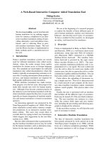
Solution - The one line diagram of the proposed system is shown in Figure 1.1.
The required system studies are:
•
•
•
•
•
•
•
Load flow analysis - To make sure that the line and transformer loadings are
within acceptable limits.
Short circuit studies - To make sure that the circuit breaker ratings and relay
settings are performed to meet the new load flow conditions.
Transient stability studies - To ensure that the system is stable under desired
operating and some contingency conditions.
Cable ampacity studies - To select the 138 kV cable.
Ground grid analysis - Ground grid for the substation and generating station
and related safety performance.
Protection coordination studies - To get all the relay settings.
Switching surge analysis - For insulation coordination.
PROBLEMS
1.
A 520 MW cogeneration plant is to be developed at 13.8 kV level. The plant
will consist of six gas turbine units each 70 MW, 13.8 kV and two steam
turbine units with a rating of 50 MW, 13.8 kV each. The voltage is to be
stepped up to 345 kV at the local substation and the power is to be delivered
through a three-phase overhead line of 3 miles. Draw a one-line diagram of the
system and identify the ratings of the circuit breakers and step up transformer
units. What are the system planning studies required for this project? Refer to
Figure 1.1.
2.
Is it necessary for the above developer (Problem 1) to perform harmonic
analysis? Explain.
3.
There is a political form opposing the electric distribution system in a school
district. This is a health-related issue due to an overhead line. The electric
utility planners want you to look into this subject and recommend to them
suitable studies to be performed. What will be the recommendation?
4.
A 230 kV transmission line is being installed between two substations at a
distance of 35 miles apart. There is a 340 feet river crossing involved in this
project and it was planned to install one tall tower at each end of the riverbank.
There will be one dead end tower following the tall tower for mechanical
considerations. Is there a need to perform special studies to reduce any risk
associated with this installation?
Copyright 2002 by Marcel Dekker. All Rights Reserved.
138kV
Circuit Breaker
2 miles
D138kVBus
ST Unit
MVA = 70
13.8 kV
170 MVA
13.8kV/13.8kV/138kV
Three Winding Transformer
Figure 1.1 One-Line Diagram of the Power Plant for Problem 1
5.
A generating plant is proposed with four 200 MW generators as shown in
Figure 1.2. There are two step-up transformers and a ring bus arrangement to
connect the generators to the utility system. In order to proceed with the
project, what power system studies are required?
200 MW
200 MW
200 MW
200 MW
Line 4
Figure 1.2 One-Line Diagram of the Proposed Generating Plant and Ring Bus
REFERENCES
1.
ANSI/IEEE Standard: 141, IEEE Recommended Practice for Electrical
Distribution for Industrial Plants, 1993 (Red Book).
2.
ANSI/IEEE Standard: 399, IEEE Recommended Practice for Power
System Analysis, 1990 (Brown Book).
Copyright 2002 by Marcel Dekker. All Rights Reserved.
2
LINE CONSTANTS
2.1 OVERHEAD TRANSMISSION LINE PARAMETERS
Transmission line parameters are used in the voltage drop calculations, load flow,
stability analysis, short circuit study, line loading calculations, transient analysis and
the performance evaluation of the lines under various loading conditions. The line
parameters are evaluated based on the installed line and tower configuration data.
The basic theory of line parameter calculations is involved and is explained well in
Reference [2]. The line constant calculation procedures suitable for computer-aided
analysis are discussed in this section.
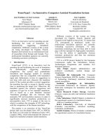
Series impedance - The general method is well suited for the calculation of the
overhead line parameters as described in [1]. This procedure is explained using a
three-phase, 4 wire system shown in Figure 2.1. The voltage drop along any
conductor is proportional to the current. In steady state, the relation between the
voltage drop, impedance and the current is given by:
dV
[—] = [Z] [I]
(2.1)
dx
dl
[—] = jco[C] [V]
(2.2)
dx
Where
[I]
[Z]
[V]
= Vector of phasor currents
= Series impedance matrix
= Vector of phasor voltages measured phase to ground
Copyright 2002 by Marcel Dekker. All Rights Reserved.
I iy
} NEUTRAL CONDUCTOR
\
2.8M
I
R
•T
4M
r
15. 9M
>r
Q
°
2.8M
4k
2.8M
C
F
I
18
13. 4 M
1
1
4M
1.
Figure 2.1 A Three-Phase, 4 Wire Overhead Transmission Line
where the self impedance (Zjj) and the mutual impedance (Z;k) are:
— + AXii)
(2.3)
(2.4)
where the complex depth pp is:
(2.5)
R
h
dik
Dik
GMR
x
(0
AR
= Resistance of the conductor, Ohms/km
= Average height of the conductor above the ground, m
= Distance between conductor i and k, m (see Figure 2.2)
= Distance between conductor i and image conductor k, m
= Geometric mean radius of conductor i, cm
= Horizontal distance between conductors, m
= Angular frequency, Radians/s
= Carson's correction term for resistance due to ground return effects
Copyright 2002 by Marcel Dekker. All Rights Reserved.