IP Addressing
Bạn đang xem bản rút gọn của tài liệu. Xem và tải ngay bản đầy đủ của tài liệu tại đây (617.09 KB, 46 trang )
3
IP Addressing
CERTIFICATION OBJECTIVES
3.01 TCP/IP Protocol Stack
3.02 IP Addressing Introduction
3.03 Subnetting
3.04 Planning IP Addressing
3.05 Figuring Out IP Address Components
✓
Two-Minute Drill
Q&A
Self Test
CertPrs8 / CCNA Cisco Certified Network Associate Study Guide / Deal / 222934-9 / Chapter 3
Blind Folio 3:1
D:\omh\CertPrs8\934-9\ch03.vp
Monday, August 04, 2003 10:58:47 AM
Color profile: Generic CMYK printer profile
Composite Default screen
T
he Transmission Control Protocol/Internet Protocol (TCP/IP) is a standard
that includes many protocols. It defines how machines on an internetwork can
communicate with each other. It was initially funded by and developed for DARPA
(Defense Advanced Research Protects Agency), which is a conglomeration of U.S. military and
government organizations. Developed initially for the government, it was later made available
to the public, mainly seen on Unix systems. First specified in RFC 791, it has become the
defacto standard for networking protocols. The Internet uses TCP/IP to carry data between
networks, and most corporations today use TCP/IP for their networks. This chapter will
provide an overview of TCP/IP, including some of its more important protocols, as well as
IP addressing.
CERTIFICATION OBJECTIVE 3.01
TCP/IP Protocol Stack
To help articulate how data is moved between devices running TCP/IP, a model was
developed that resembles the OSI Reference Model discussed in Chapter 2. Table 3-1
compares the two models. The following sections will cover the layers of the TCP/IP
Protocol stack.
Application Layer
One main difference between the OSI Reference Model and TCP/IP’s model is that
TCP/IP lumps together the application, presentation and session layers into one layer,
called the application layer. Here are some common TCP/IP applications Cisco devices
support: DNS, HTTP, SNMP, telnet, and TFTP.
2
Chapter 3: IP Addressing
CertPrs8 / CCNA Cisco Certified Network Associate Study Guide / Deal / 222934-9 / Chapter 3
It is VERY important
that you understand ALL aspects of IP
addressing. Therefore, spend a lot of time
on this chapter. If you don’t understand IP
addressing when taking the exam, you
will have a difficult time in passing it.
This Exam Watch goes for all three
exams: INTRO, ICND, and CCNA.
D:\omh\CertPrs8\934-9\ch03.vp
Monday, August 04, 2003 10:58:47 AM
Color profile: Generic CMYK printer profile
Composite Default screen
Transport Layer
The TCP/IP transport layer is responsible for providing a logical connection between
two devices and can provide these two functions:
■
Flow control (through the use of windowing or acknowledgements)
■
Reliable connections (through the use of sequence numbers and
acknowledgements)
The transport layer packages application
layer data into segments to send to a destination
device. The remote destination is responsible
for taking the data from these segments and
forwarding it to the correct application. TCP/IP
has two transport layer protocols: Transmission
Control Protocol (TCP) and User Datagram Protocol (UDP). These protocols are
discussed in the following sections.
TCP
TCP’s main responsibility is to provide a reliable connection-oriented logical service
between two devices. It can also use windowing to implement flow control so that a
source device doesn’t overwhelm a destination
with too many segments.
TCP Segment
TCP transmits information
between devices in a data unit called a segment.
Table 3-2 shows the components of a segment.
TCP/IP Protocol Stack
3
CertPrs8 / CCNA Cisco Certified Network Associate Study Guide / Deal / 222934-9 / Chapter 3
Layer OSI Reference Model TCP/IP Protocol Stack
Layer 7 Application
Layer 6 Presentation
Layer 5 Session Application
Layer 4 Transport Transport
Layer 3 Network Internet
Layer 2 Data Link Data Link
Layer 1 Physical Physical
TABLE 3-1
Comparison
of the OSI
Reference Model
and the TCP/IP
Protocol Stack
TCP/IP’s transport layer
can provide for flow control and reliable
connections.
Here are some examples
of applications (and their ports) that use
TCP: HTTP (80), FTP (21), SMTP (25),
and telnet (23).
D:\omh\CertPrs8\934-9\ch03.vp
Monday, August 04, 2003 10:58:47 AM
Color profile: Generic CMYK printer profile
Composite Default screen
The segment is composed of a header, followed by the application data. Without any
options, the TCP header is 20-bytes in length.
TCP’s Multiplexing Function
TCP, and UDP, provide a multiplexing function
for a device: This allows multiple applications to simultaneously send and receive data.
With these protocols, port numbers are used to differentiate the connections. Port
numbers are broken into two basic categories:
well-known port numbers (sometimes called
reserved port numbers) and source connection
port numbers. Each application is assigned a
well-known port number that is typically
between 1 and 1,023. Any time you want to
make a connection to a remote application, your
application program will use the appropriate
well-known port number.
As you saw in Table 3-2, however, there happens to be two port numbers in
the segment: source and destination. When you initiate a connection to a remote
4
Chapter 3: IP Addressing
CertPrs8 / CCNA Cisco Certified Network Associate Study Guide / Deal / 222934-9 / Chapter 3
TCP Field Name
Length
(in bits) Definition
Source Port 16 Identifies which application is sending information
Destination Port 16 Identifies which application is to receive the information
Sequence Number 32 Maintains reliability and sequencing
Acknowledgement Number 32 Used to acknowledge received information
Header Length 4 Number of 32-bit words that comprise the header
Reserved Field 6 Currently not used (set to all zeroes)
Code Bits 6 Defines control functions, like synchronization
Window Size 16 Indicates the number of segments allowed to be sent before
waiting for an acknowledgment from the destination
Checksum 16 CRC of the header and encapsulated application data
Urgent Field 16 Points to the any urgent data in the segment
Options 0-32
Data Application data (not part of the TCP header)
TABLE 3-2
TCP Segment Components
Be familiar with the
TCP field names, especially the fact that
a TCP segment contains a sequence and
acknowledgment number as well as a
window size.
D:\omh\CertPrs8\934-9\ch03.vp
Monday, August 04, 2003 10:58:47 AM
Color profile: Generic CMYK printer profile
Composite Default screen
application, your operating system will pick a currently unused port number
greater than 1,023 and assign this number as the source port number. Based on
the application that you are running, the application will fill in the destination
port number with the well-known port number of the application. When the
destination receives this traffic, it looks at the destination port number and knows
which application this traffic should be directed to. This is also true for returning
traffic from the destination. This process was discussed in Chapter 2.
Port numbers are assigned by the Internet Assigned Numbers Authority (IANA).
When a vendor develops a new commercial application and wants a reserved
(well-known) port number, he applies for one to this organization. Here are some
common TCP applications with their assigned port numbers: FTP (20 and 21),
HTTP (80), SMTP (25), and telnet (23).
TCP’s Reliability
TCP provides a reliable connection between devices by using
sequence numbers and acknowledgements. Every TCP segment sent has a sequence
number in it. This not only helps the destination reorder any incoming frames that
arrived out of order, but it also provides a method of verifying if all sent segments
were received. The destination responds to the source with an acknowledgment
indicating receipt of the sent segments.
Before TCP can provide a reliable connection, it has to go through a synchronization
phase, called a three-way handshake. Here are the steps that occur during this setup
process:
1. The source sends a synchronization frame with the SYN bit marked in the
Code field. This segment contains an initial sequence number. This is referred
to as a SYN segment.
2. Upon receipt of the SYN segment, the destination responds back with its
own segment, with its own initial sequence number and the appropriate value
in the acknowledgement field indicating the receipt of the source’s original
SYN segment. This notifies the source that the original SYN segment was
received. This is referred to as a SYN/ACK segment.
3. Upon receipt of the SYN/ACK segment, the source will acknowledge receipt
of this segment by responding back to the destination with an ACK segment,
which has the acknowledgment field set to an appropriate value based on the
destination’s sequence number.
Here is a simple example of this three-way handshake:
1. Source sends a SYN: sequence number = 1
TCP/IP Protocol Stack
5
CertPrs8 / CCNA Cisco Certified Network Associate Study Guide / Deal / 222934-9 / Chapter 3
D:\omh\CertPrs8\934-9\ch03.vp
Monday, August 04, 2003 10:58:47 AM
Color profile: Generic CMYK printer profile
Composite Default screen
2. Destination responds with a SYN/ACK: sequence number = 10,
acknowledgement = 2
3. Source responds with an ACK segment: sequence number = 2,
acknowledgement = 11
In this example, the destination’s
acknowledgment (step 2) is one greater than
the source’s sequence number, indicating to the
source that the next segment expected is 2.
In the third step, the source sends the second
segment, and, within the same segment in the
Acknowledgement field, indicates the receipt
of the destination’s segment with an acknowledgment of 11--one greater than
the sequence number in the destination’s SYN/ACK segment. This process was
described in Chapter 2.
Windowing
TCP allows the regulation of the flow of segments, ensuring that
one device doesn’t flood another device with too many segments. TCP uses a sliding
windowing mechanism to assist with flow control. For example, if you have a window
size of 1, a device can send only one segment, and then must wait for a corresponding
acknowledgement before sending the next segment. If the window size is 20, a device
can send 20 segments and then has to wait for an acknowledgment before sending 20
additional segments.
The larger the window size is for a connection, the less acknowledgments that
are sent, thus making the connection more efficient. Too small a window size can
affect throughput, since a device has to send a small number of segments, wait for an
acknowledgment, send another bunch of small segments, and wait again. The trick
is to figure out an optimal window size: one that allows for the best efficiency based
on the current conditions in the network and on the two devices.
6
Chapter 3: IP Addressing
CertPrs8 / CCNA Cisco Certified Network Associate Study Guide / Deal / 222934-9 / Chapter 3
TCP uses a three-way
handshake to set up a reliable connection:
SYN, SYN/ACK, and ACK.
TCP employs a positive
acknowledgement with retransmission (PAR)
mechanism to recover from lost segments.
The same segment will be repeatedly resent,
with a delay between each segment, until
an acknowledgement is received from the
destination. The acknowledgement
contains the sequence number of the
segment received and verifies receipt of
all sent prior segments. This eliminates the
need for multiple acknowledgements and
resending acknowledgements.
D:\omh\CertPrs8\934-9\ch03.vp
Monday, August 04, 2003 10:58:48 AM
Color profile: Generic CMYK printer profile
Composite Default screen
A nice feature of this process is that the window size can be dynamically changed
through the lifetime of the connection. This is important because many more
connections may come into a device with varying bandwidth needs. Therefore, as
a device becomes saturated with segments from many connections, it can, assuming
that these connections are using TCP, lower the window size to slow the flow of
segments coming into it. TCP windowing is covered in RFC 793 and 813.
UDP
Where TCP provides a reliable connection, UDP provides an unreliable connection. UDP
doesn’t go through a 3-way handshake to set up a connection--it just begins sending its
information. Likewise, UDP doesn’t check to see if sent segments were received by a
destination; in other words, it doesn’t have an acknowledgment process. Typically, if an
acknowledgment process is necessary, the transport layer (UDP) won’t provide it; instead,
the application itself, at the application layer, will provide this verification.
Given these deficiencies, UDP does have an
advantage over TCP: it has less overhead. For
example, if you only need to send one segment,
and receive one segment back, and that’s the
end of the transmission, it makes no sense to
go through a 3-way handshake to first establish
a connection and then send and receive the
two segments: this is not very efficient. DNS
queries are a good example where the use of
UDP makes sense. Of course, if you are sending
a large amount of data to a destination, and need to verify that it was received,
then TCP would be a better transport mechanism.
Table 3-3 contains the components of a UDP segment. Examining this table, you
can notice a lot of differences between a UDP and TCP segment. First, since UDP
TCP/IP Protocol Stack
7
CertPrs8 / CCNA Cisco Certified Network Associate Study Guide / Deal / 222934-9 / Chapter 3
UDP is more efficient that
TCP because it has less overhead. Here
are some examples of UDP applications,
along with their assigned port numbers:
DNS queries (53), RIP (520), SNMP (161),
and TFTP (69).
UDP Field Name
Length
(in bits) Definition
Source Port 16 Identifies the sending application
Destination Port 16 Identifies the receiving application
Length 16 Denotes the size of the UDP segment
Checksum 16 Provides a CRC on the complete UDP segment
Data Application data (not part of the UDP header)
TABLE 3-3
UDP Segment Components
D:\omh\CertPrs8\934-9\ch03.vp
Monday, August 04, 2003 10:58:48 AM
Color profile: Generic CMYK printer profile
Composite Default screen
is connectionless, there is no need for sequence and acknowledgment numbers. And
second, since there is no flow control, there is no need for a window size field. As you
can see, UDP is a lot simpler, and more efficient, than TCP. Any control functions that
need to be implemented for the connection are not done at the transport layer--instead,
these are handled at the application layer.
Internet Layer
Layer-3 of the TCP/IP protocol stack is called the Internet layer. The corresponding layer
in the OSI Reference Model is the network layer. The Internet Protocol (IP) is just one
of the protocols that reside at this layer. It is very
common in the industry to hear people refer to
TCP/IP as just “IP”; however, this is a misnomer,
since IP is just one of many protocols within
TCP/IP. Other IP protocols include ARP, RARP,
ICMP, OSPF, and others. The next few sections
explain the components of an IP packet and some
of the protocols that function at the Internet layer.
IP Datagram
Where the transport layer uses segments to transfer information between machines,
the Internet layer uses datagrams. Datagram is just another word for packet. Table 3-4
shows the components of the IP datagram. Without
any options, the IP header is 20 bytes in length.
The main function of the IP datagram is to
carry protocol information for either Internet layer
protocols or encapsulated transport layer protocols.
To designate what protocol the IP datagram is
carrying in the data field, the IP datagram carries
the protocol’s number in the Protocol field of the
datagram.
ICMP
The Internet Control Message Protocol (ICMP) is used to send error and control
information between TCP/IP devices. ICMP, defined in RFC 792, includes many
different messages that devices can generate or respond to. Here is a list of these
messages: Address Reply, Address Request, Destination Unreachable, Echo, Echo
Reply, Information Reply, Information Request, Parameter Problem, Redirect,
Subnet Mask Request, Time Exceeded, Timestamp, and Timestamp Reply.
8
Chapter 3: IP Addressing
CertPrs8 / CCNA Cisco Certified Network Associate Study Guide / Deal / 222934-9 / Chapter 3
IP provides a
connectionless, unreliable connection to
other devices. If reliability and flow control
are required, TCP (transport layer) can
provide this.
IP is uses a TTL field to
limit the number of hops a packet can
travel. Here are some common protocols
and their protocol numbers: ICMP (1),
IGRP (9), IPv6 (41), TCP (6), and UDP (17).
D:\omh\CertPrs8\934-9\ch03.vp
Monday, August 04, 2003 10:58:48 AM
Color profile: Generic CMYK printer profile
Composite Default screen
One of the most common implementations
using ICMP is ping. Ping uses a few ICMP
messages, including echo, echo request, and
destination unreachable. Ping is used to test
whether or not a destination is available.
A source generates an ICMP echo packet.
If the destination is available, it will respond
back with an echo reply. If it isn’t available,
a router will respond back with a destination
unreachable message. Trace is an application that will list the IP addresses of the
routers along the way to the destination, displaying the path the packet took to
reach the destination.
TCP/IP Protocol Stack
9
CertPrs8 / CCNA Cisco Certified Network Associate Study Guide / Deal / 222934-9 / Chapter 3
IP Field Name
Length
(in bits) Definition
Version 4 IP version number, like IPv4
Header Length 4 Length of the IP header in 32-bit word values
Priority and TOS (Type
of Service)
8 Defines how the IP network should treat the datagram
Total Length 16 Length of the IP datagram, including the header and encapsulated
data
Identification 16
Flags 3 Is set if the datagram is a fragment; also used for other purposes
Fragment Offset 13 Defines information about the datagram if it is a fragment
TTL (Time-To-Live) 8 Sets the number of allowed layer-3 hops the datagram is allowed to
traverse
Protocol 8 Identifies the protocol (like TCP, UDP, ICMP, OSPF, etcetera)
that was used to encapsulate payload information
Header Checksum 16 Checksum on just the IP header fields
Source IP Address 32 IP address of the source device
Destination IP address 32 IP address of the destination device
Options 0-32
Data Protocol information (like an encapsulated UDP segment or ICMP
information)
TABLE 3-4
IP Datagram Components
Two common applications
that use ICMP are ping and traceroute
(trace). Ping uses an ICMP echo message
to test connectivity to a remote device.
D:\omh\CertPrs8\934-9\ch03.vp
Monday, August 04, 2003 10:58:48 AM
Color profile: Generic CMYK printer profile
Composite Default screen
ARP and RARP
The Address Resolution Protocol (ARP) is an Internet layer protocol that helps TCP/IP
devices find other devices in the same broadcast domain. ARP uses a local broadcast to
discover neighboring devices. Basically, ARP resolves an IP address of a destination to
the MAC address of the destination on the same data link layer medium. Remember
that for two devices to talk to each other in Ethernet, the data link layer uses MAC
addresses to differentiate the machines on the segment. And that when devices talk to
each other at the data link layer, they need to know the destination’s MAC address.
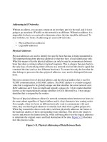
The top part of Figure 3-1 shows an example of the use of ARP. In this example PC-A
wants to send information directly to PC-B. PC-A knows PC-B’s IP address, however, it
doesn’t know PC-B’s Ethernet MAC address. To resolve the IP to MAC address, PC-A
generates an IP ARP. In the ARP datagram, the source IP address is 10.1.1.1 and the
destination is 255.255.255.255—every device on the segment. PC-A includes PC-B’s IP
address in the data field of the ARP datagram. This is encapsulated into an Ethernet
10
Chapter 3: IP Addressing
CertPrs8 / CCNA Cisco Certified Network Associate Study Guide / Deal / 222934-9 / Chapter 3
FIGURE 3-1
ARP and RARP Examples
D:\omh\CertPrs8\934-9\ch03.vp
Monday, August 04, 2003 10:58:48 AM
Color profile: Generic CMYK printer profile
Composite Default screen
frame, with a source MAC address of 0000.0CCC.1111 and a destination MAC address
of FFFF.FFFF.FFFF and is then placed on the wire. Both PC-B and PC-C see this frame.
Both devices notice the data link layer broadcast address and assume that this frame is for
them, so they pass it up to the Internet layer. Again, there is a broadcast address in the
destination IP address field, so both devices examine the data payload. PC-B notices
that this is an ARP and that this is its IP address, and therefore responds directly back
to PC-A with PC-B’s MAC address. PC-C, however, sees that this is not an ARP for
its MAC address and ignores the datagram.
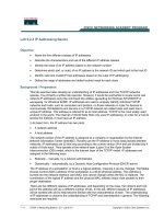
Figure 3-2 shows a more detailed example of the use of ARP. In this example,
PC-A wants to connect to PC-B using IP. The source address is 1.1.1.1 (PC-A)
and the destination is PC-B (2.2.2.2). Since the two devices are on different
networks, a router is used to communicate between the networks. Therefore, if
PC-A wants to send something to PC-B, it has to be via the intermediate router.
This communication does not occur at the network layer using IP; however, it
occurs at the data link layer. I’ll assume that Ethernet is being used in this example.
The first thing that PC-A will do is to determine if the destination is local to this
subnet or on another subnet (I’ll discuss this process when I cover IP addressing and
subnetting later in this chapter). In this example, it’s a remote location, so PC-A will
ARP for the default gateway’s MAC address--note that one thing you must configure
TCP/IP Protocol Stack
11
CertPrs8 / CCNA Cisco Certified Network Associate Study Guide / Deal / 222934-9 / Chapter 3
FIGURE 3-2
ARP Example with a Router
D:\omh\CertPrs8\934-9\ch03.vp
Monday, August 04, 2003 10:58:48 AM
Color profile: Generic CMYK printer profile
Composite Default screen
on PC-A, besides it’s own IP address and subnet mask, is the default gateway address.
This is shown in step 1 of Figure 3-2. In step 2, the router responds back with the
MAC address of the interface connected to PC-A. In step 3, PC-A takes the IP packet
with the source and destination IP addresses (the source is 1.1.1.1 and the destination
is 2.2.2.2) and encapsulates this in an Ethernet frame, with the source MAC address
of PC-A and the destination MAC address of the router.
When the router receives the Ethernet frame, it compares the frame to its own MAC
address, which it matches. The router strips off the Ethernet frame and makes a routing
decision based on the destination address of 2.2.2.2. In this case, the network is directly
connected to the router’s second interface, which also happens to be Ethernet. In step 4,
the router ARPs for the MAC address of 2.2.2.2 (PC-B) and receives the response
in step 5. The router then encapsulates the IP packet in an Ethernet frame in step 6,
placing its second interface’s MAC address, which is sourcing the frame, in the source
MAC address field and PC-B’s MAC address in the destination field. When PC-B
receives this, it knows the frame is for itself (matching destination MAC address)
and that PC-A originated the IP packet that’s encapsulated).
Note that in this example, the IP packet was not altered by the router, but two
Ethernet frames are used to get the IP packet to the destination. Also, each device
will keep the MAC addresses in an ARP table, so the next time PC-A needs to send
something to PC-B, the devices will not have to ARP each other again.
RARP is sort of the reverse of an ARP. In an ARP, the device knows the layer-3
address, but not the data-link layer address. With a RARP, the device doesn’t have
an IP address and wants to acquire one. The only address that this device has is a
MAC address. Common protocols that use RARP are BOOTP and the Dynamic
Host Configuration Protocol (DHCP).
The bottom part of Figure 3-1 shows a RARP example. In this example, PC-D
doesn’t have an IP address and wants to acquire one. It generates a data-link layer
broadcast (FFFF.FFFF.FFFF) with an encapsulated RARP request. This examples
assumes that the RARP is associated with BOOTP. If there is a BOOTP server on
12
Chapter 3: IP Addressing
CertPrs8 / CCNA Cisco Certified Network Associate Study Guide / Deal / 222934-9 / Chapter 3
Be familiar with what
device talks to what at both layer-2 and
layer-3. With a router between the source
and destination, the source, at layer-2, uses
its own MAC address as the source but
the default gateway MAC address as the
destination. Note that the IP addresses used
at layer-3 are not changed by the router.
D:\omh\CertPrs8\934-9\ch03.vp
Monday, August 04, 2003 10:58:49 AM
Color profile: Generic CMYK printer profile
Composite Default screen
the segment, and if it has an IP address for this machine, it will respond back. In this
example, the BOOTP server, 10.1.1.15, has an address (10.1.1.4) and assigns this to
PC-D, sending this address as a response to PC-D.
CERTIFICATION OBJECTIVE 3.02
IP Addressing Introduction
Probably one of the most confusing aspects of the TCP/IP protocol stack is the
addresses used at the Internet layer, referred to as IP addresses. The remainder of this
chapter will focus on IP addressing, its components, and how to plan for addressing.
Please note that there are two different versions of TCP/IP: IPv4 and IPv6. Only IPv4
is covered in this book.
IPv4 addresses are 32 bits in length. However, to make the addresses readable,
they are broken into four bytes (called octets), with a period (decimal) between
each byte. So that the address is understandable to the human eye, the four sets
of binary numbers are then converted to decimal. Let’s look at a simple example:
11111111111111111111111111111111, which is 32 1’s. This is broken up into
four octets, like this: 11111111.11111111.11111111.1111111. Then each of these
octets are converted into decimal, resulting in 255.255.255.255. The format of this
address is commonly called dotted decimal.
Bit Values
Before you can begin to understand the conversion process, you need to understand
binary mathematics. Computers and networking devices process everything in binary. In
a byte (octet), there are eight bits. Each bit, when enabled, represents a specific decimal
value. Table 3-5 shows the conversion of a specific bit position when it is enabled. In this
table, the bit positions are labeled from left-to-right, where the left-most bit is the most
IP Addressing Introduction
13
CertPrs8 / CCNA Cisco Certified Network Associate Study Guide / Deal / 222934-9 / Chapter 3
DHCP allows devices
to dynamically acquire their addressing
information. This information can include
a client IP address and subnet mask, a
default gateway, DNS, TFTP, and WINS
server addresses, a domain name, and
the length of the lease of the client
address.
D:\omh\CertPrs8\934-9\ch03.vp
Monday, August 04, 2003 10:58:49 AM
Color profile: Generic CMYK printer profile
Composite Default screen
significant and the right-most bit is the least-significant. A bit can contain one of two
values: 0 or 1. If it is enabled (set to 1), then that equates to a particular decimal value,
shown in the second row of Table 3-5. If it is disabled (set to 0), then this equates to a
decimal value of zero. Higher-order bits are the ones with a higher-numbered bit position
(like 8) while lower-order bits are the ones with a lower-numbered bit position (like 1).
To convert the binary byte value to a decimal value, you look at all the bits that are
turned on and add up the equivalent decimal values.
For example, assume that you had a byte
with a value of 11000001. Bits 8, 7, and 1 are
on, so add up the associated decimal values to
get the corresponding decimal equivalent of
the byte value: 128 + 64+1=193. If you had
a byte value of 00110011, the decimal value
would be: 32 + 16+2+1=51.Ifallthebit
positions where set to 0, then the decimal value would be 0. If all the bit positions
were set to 1, the equivalent decimal value would be: 128 + 64 + 32 + 16 + 8 + 4 +
2 + 1 = 255. Given this, a byte value can range from 0 to 255.
Hexadecimal Conversion
Even though IP addressing deals with octal, decimal, and binary notations, you might
be required to perform decimal to hexadecimal conversion and vice versa. Therefore,
since part of this chapter deals with numeric conversions, I’ll briefly cover the process
of performing decimal/hexadecimal conversion.
First, as you already know, binary has two possible values in a bit position and octal
has 8 bit positions, allowing you to represent numbers from 0-255 in a byte (8 bits). And
in decimal, you have values that range from 0-9
(10 values). Hexadecimal has a range of 16 values:
0, 1, 2, 3, 4, 5, 6, 7, 8, 9, A, B, C, D, E, and F. As
an example, a decimal 10 is equivalent to A in
hexadecimal. A decimal 17 is equivalent to 10
in hexadecimal. When dealing with hexadecimal,
a hex digit is represented in four bits. Table 3-6
lists a handy conversion chart.
14
Chapter 3: IP Addressing
CertPrs8 / CCNA Cisco Certified Network Associate Study Guide / Deal / 222934-9 / Chapter 3
Remember how to convert
a binary 8-bit value to a decimal number
and vice versa.
Bit Position 87654321
Decimal Value 1286432168421
TABLE 3-5
Binary to decimal conversion for byte values.
You should be familiar
with converting binary to both decimal
and hexadecimal, as well as hexadecimal
to decimal or vice versa.
D:\omh\CertPrs8\934-9\ch03.vp
Monday, August 04, 2003 10:58:49 AM
Color profile: Generic CMYK printer profile
Composite Default screen
For example, if you had an 8-bit value of 10000001, break this up into two 4-
bit values, since a hexadecimal value is represented in 4 bits: 1000 and 00001.
In hexadecimal, this value would be 8 and 0, or 80. If you had an 8-bit value
of 11011001, this would be D9 in hexadecimal.
Classes of Addresses
Recall from Chapter 2 that logical, or layer-3, addresses, have two components: a
network and host number. The network number uniquely identifies a segment in
the network and a host number uniquely identifies a device on a segment. The
combination of these two numbers must be unique throughout the entire network.
TCP/IP uses the same two components for addressing, but does add a twist by breaking
IP Addressing Introduction
15
CertPrs8 / CCNA Cisco Certified Network Associate Study Guide / Deal / 222934-9 / Chapter 3
Decimal Binary Hexadecimal
0 0000 0
1 0001 1
2 0010 2
3 0011 3
4 0100 4
5 0101 5
6 0110 6
7 0111 7
8 1000 8
9 1001 9
10 1010 A
11 1011 B
12 1100 C
13 1101 D
14 1110 E
15 1111 F
TABLE 3-6
Binary to Decimal
to Hexadecimal
Conversion for
Bit Values
D:\omh\CertPrs8\934-9\ch03.vp
Monday, August 04, 2003 10:58:49 AM
Color profile: Generic CMYK printer profile
Composite Default screen
up network numbers into five classes: Class A, B, C, D, and E. Each of these classes
has a predefined network and host boundary:
■
With a Class A address, the first byte is a network number (8 bits) and the
last 3 bytes are for host numbers (24 bits)
■
With a Class B address, the first two bytes
are a network number (16 bits) and the last
2 bytes are for host numbers (16 bits)
■
With a Class C address, the first three bytes
are a network number (24 bits) and the last
1 byte is for host numbers (8 bits)
■
Class D addresses are used for multicasting
and Class E addresses are reserved
Distinguishing Between Classes of Addresses
Given the above distinction, it would seem that addressing for IP is easy. However, what
distinguishes the different classes of addresses are what the first bit to 5 bits is set to:
■
Class A addresses always begin with a “0” in the highest order bit
■
Class B addresses always begin with “10” in the highest order bits
■
Class C addresses always begin with “110” in the highest order bits
■
Class D addresses always begin with “1110” in the highest order bits
■
Class E addresses always begin with “11110” in the highest order bits
When talking about the highest-order bit
or bits, this includes all 32 bits. Therefore, this
would be the very first bit on the left of the
address (the most significant bit). If the first
octet contains 1000001, this represents 129
in decimal, which would be a Class B address.
Network Numbers and Classes of Addresses
Given the above distinctions with the assigned high-order bit values, it is easy to
predict, for a given address, what class of network numbers it belongs to:
16
Chapter 3: IP Addressing
CertPrs8 / CCNA Cisco Certified Network Associate Study Guide / Deal / 222934-9 / Chapter 3
Remember the 5 classes
of IP addresses, and the fact that Class A
addresses have, by default, 8 network bits,
Class B 16 bits and Class C 24 bits.
Remember the binary
values that IP addresses begin with and be
able to determine, by looking at the first
binary byte, whether the address is a Class
A, B, C, D, or E address.
D:\omh\CertPrs8\934-9\ch03.vp
Monday, August 04, 2003 10:58:49 AM
Color profile: Generic CMYK printer profile
Composite Default screen
■
Class A addresses range from 1-126: 0 is reserved and represents all IP
addresses; 127 is a reserved address and is used for testing, like a loopback
on an interface: 00000001-01111111.
■
Class B addresses range from 128-191: 10000000-10111111.
■
Class C addresses range from 192-223: 11000000-11011111.
■
Class D addresses range from 224-239: 11100000-11101111.
■
Class E addresses range from 240-254: 255 is a reserved address and is used for
broadcasting purposes.
Given the above restrictions with beginning bit values, it is fairly easy to predict
what address belongs to what class.
When you are dealing with IP addresses, there are always two numbers reserved
for a given network number: the first address in the network represents the network’s
address, and the last address in the network represents the broadcast address for this
network, commonly called a directed broadcast. When you look at IP itself, there
are two IP addresses reserved: 0.0.0.0 (the very first address), which represents all
IP addresses, and 255.255.255.255 (the very last address), which is the local
broadcast address (all devices should process this datagram).
Within this range of addresses for Class A,
B, and C addresses, there are some reserved
addresses, commonly called Private Addresses.
All the other addresses in these classes are
called public addresses. Anyone can use private
addresses; however, this creates a problem if you
want to access the Internet. Remember that
each device in the network (in this case, this
includes the Internet) must have a unique IP
address. If two networks are using the same private addresses, then you would run
into reachability issues. In order to access the Internet, your source IP addresses must
IP Addressing Introduction
17
CertPrs8 / CCNA Cisco Certified Network Associate Study Guide / Deal / 222934-9 / Chapter 3
Class A addresses range
from 1-126, Class B from 128-192,
Class C from 192-223, Class D from
224-239 and Class E from 240-254. 127
is reserved for the loopback interface
(internal testing). Also remember the
ranges in binary.
Remember the
list of private networks, which
cannot be used in public networks:
10.0.0.0, 172.16.0.0-172.31.0.0,
and 192.168.0.0-192.168.255.0.
D:\omh\CertPrs8\934-9\ch03.vp
Monday, August 04, 2003 10:58:49 AM
Color profile: Generic CMYK printer profile
Composite Default screen
have a unique Internet public address. This can be accomplished through address
translation. Here is a list of private addresses, which are assigned in RFC 1918:
■
Class A: 10.0.0.0-10.255.255.255 (1 Class A network)
■
Class B: 172.16.0.0-172.31.255.255 (16 Class B networks)
■
Class C: 192.168.0.0-192.168.255.255 (256 Class C networks)
Private and public addresses, as well as address translation, are discussed in
Chapter 14.
IP Address Components
As was mentioned earlier, there are two components to addressing: network and host.
The host portion is actually broken into three subcomponents: network address, host
addresses, and directed broadcast address.
The very first address in a network number is called the network address, or
wire number. This address is used to uniquely identify one segment from all of the
other segments in the network. The last address in the network number is called
the directed broadcast address, and is used to represent all hosts on this network
segment. A directed broadcast is similar to a local broadcast. The main difference
is that routers will not propagate local broadcasts, but can propagate directed
broadcasts. Any address between the network address and the directed broadcast
address is a host address for the segment. You use these middle addresses to assign
to host devices on the segment, like PCs, servers, routers, and switches.
Network and Directed Broadcast Addresses
When dealing with a network address, all of the host bits in the host portion of the address
are set to zeros. If all of the host bits in a network number are set to ones, making it the very
last address, then this is the directed broadcast address. Any combination of bit values
between these two numbers in the host portion of the address is considered a host address.
As example, 192.1.1.0 is a Class C address and is also a network number. If you
recall from earlier in this chapter, the Class C addresses range from 192-223 in the
18
Chapter 3: IP Addressing
CertPrs8 / CCNA Cisco Certified Network Associate Study Guide / Deal / 222934-9 / Chapter 3
Each network has two
reserved addresses: a network number
(the first address) and a directed broadcast
(the last address). Any addresses between
these two values can be assigned to
networking devices on the segment.
D:\omh\CertPrs8\934-9\ch03.vp
Monday, August 04, 2003 10:58:49 AM
Color profile: Generic CMYK printer profile
Composite Default screen