Tài liệu mở rộng quản trị mạng IP Addressing
Bạn đang xem bản rút gọn của tài liệu. Xem và tải ngay bản đầy đủ của tài liệu tại đây (129.47 KB, 48 trang )
Configuring IP Addressing P1C-5
Configuring IP Addressing
This chapter describes how to configure IP addressing. For a complete description of the commands
in this chapter, refer to the “IP Addressing Commands” chapter of the Network Protocols Command
Reference, Part 1. To locate documentation of other commands that appear in this chapter, use the
command reference master index or search online.
IP Addressing Task List
A basic and required task for configuring IP is to assign IP addresses to network interfaces. Doing
so enables the interfaces and allows communication with hosts on those interfaces using IP.
Associated with this task are decisions about subnetting and masking the IP addresses.
To configure various IP addressing features, complete the tasks in the following sections. The first
task is required; the remaining are optional.
•
Assign IP Addresses to Network Interfaces
•
Configure Address Resolution Methods
•
Enable IP Routing
•
Enable IP Bridging
•
Enable Integrated Routing and Bridging
•
Configure a Routing Process
•
Configure Broadcast Packet Handling
•
Configure Network Address Translation (NAT)
•
Monitor and Maintain IP Addressing
At the end of this chapter, the examples in the “IP Addressing Examples” section illustrate how you
might establish IP addressing in your network.
Assign IP Addresses to Network Interfaces
An IP address identifies a location to which IP datagrams can be sent. Some IP addresses are
reserved for special uses and cannot be used for host, subnet, or network addresses. Table 1 lists
ranges of IP addresses, and shows which addresses are reserved and which are available for use.
P1C-6 Network Protocols Configuration Guide, Part 1
Assign IP Addresses to Network Interfaces
Table 1 Reserved and Available IP Addresses
The official description of IP addresses is found in RFC 1166, “Internet Numbers.”
To receive an assigned network number, contact your Internet service provider.
An interface can have one primary IP address. To assign a primary IP address and a network mask
to a network interface, perform the following task in interface configuration mode:
A mask identifies the bits that denote the network number in an IP address. When you use the mask
to subnet a network, the mask is then referred to as a subnet mask.
Note
We only support network masks that use contiguous bits that are flush left against the network
field.
The tasks required to enable additional, optional, IP addressing features are contained in the
following sections:
•
Assign Multiple IP Addresses to Network Interfaces
•
Enable Use of Subnet Zero
•
Enable Classless Routing Behavior
•
Enable IP Processing on a Serial Interface
Class Address or Range Status
A 0.0.0.0
1.0.0.0 to 126.0.0.0
127.0.0.0
Reserved
Available
Reserved
B 128.0.0.0 to 191.254.0.0
191.255.0.0
Available
Reserved
C 192.0.0.0
192.0.1.0 to 223.255.254
223.255.255.0
Reserved
Available
Reserved
D 224.0.0.0 to 239.255.255.255 Multicast group
addresses
E 240.0.0.0 to 255.255.255.254
255.255.255.255
Reserved
Broadcast
Task Command
Set a primary IP address for an interface. ip address ip-address mask
Assign IP Addresses to Network Interfaces
Configuring IP Addressing P1C-7
Assign Multiple IP Addresses to Network Interfaces
The software supports multiple IP addresses per interface. You can specify an unlimited number of
secondary addresses. Secondary IP addresses can be used in a variety of situations. The following
are the most common applications:
•
There might not be enough host addresses for a particular network segment. For example,
suppose your subnetting allows up to 254 hosts per logical subnet, but on one physical subnet
you must have 300 host addresses. Using secondary IP addresses on the routers or access servers
allows you to have two logical subnets using one physical subnet.
•
Many older networks were built using Level 2 bridges, and were not subnetted. The judicious use
of secondary addresses can aid in the transition to a subnetted, router-based network. Routers on
an older, bridged segment can easily be made aware that many subnets are on that segment.
•
Two subnets of a single network might otherwise be separated by another network. You can
create a single network from subnets that are physically separated by another network by using
a secondary address. In these instances, the first network is extended, or layered on top of the
second network. Note that a subnet cannot appear on more than one active interface of the router
at a time.
Note
If any router on a network segment uses a secondary address, all other routers on that same
segment must also use a secondary address from the same network or subnet.
To assign multiple IP addresses to network interfaces, perform the following task in interface
configuration mode:
Note
IP routing protocols sometimes treat secondary addresses differently when sending routing
updates. See the description of IP split horizon in the “Configuring IP Enhanced IGRP,”
“Configuring IGRP,” or “Configuring RIP” chapters for details.
See the “Creating a Network from Separated Subnets Example” section at the end of this chapter for
an example of creating a network from separated subnets.
Enable Use of Subnet Zero
Subnetting with a subnet address of zero is illegal and strongly discouraged (as stated in RFC 791)
because of the confusion that can arise between a network and a subnet that have the same addresses.
For example, if network 131.108.0.0 is subnetted as 255.255.255.0, subnet zero would be written as
131.108.0.0—which is identical to the network address.
Task Command
Assign multiple IP addresses to network
interfaces.
ip address ip-address mask secondary
P1C-8 Network Protocols Configuration Guide, Part 1
Assign IP Addresses to Network Interfaces
You can use the all zeros and all ones subnet (131.108.255.0), even though it is discouraged.
Configuring interfaces for the all ones subnet is explicitly allowed. However, if you need the entire
subnet space for your IP address, perform the following task in global configuration mode to enable
subnet zero:
Enable Classless Routing Behavior
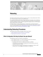
At times, a router might receive packets destined for a subnet of a network that has no network
default route. Figure 2 shows a router in network 128.20.0.0 connected to subnets 128.20.1.0,
128.20.2.0, and 128.20.3.0. Suppose the host sends a packet to 128.20.4.1. By default, if the router
receives a packet destined for a subnet it does not recognize, the router discards the packet.
Figure 2 No IP Classless Routing
In Figure 3, classless routing is enabled in the router. Therefore, when the host sends a packet to
128.20.4.1, instead of discarding the packet, the router forwards the packet to the best supernet route.
Task Command
Enable the use of subnet zero for interface
addresses and routing updates.
ip subnet-zero
Host
128.20.1.0
128.20.2.0
128.20.3.0
128.20.4.1
128.0.0.0/8
128.20.4.1
Bit bucket
S3285
128.20.0.0
Assign IP Addresses to Network Interfaces
Configuring IP Addressing P1C-9
Figure 3 IP Classless Routing
To have the Cisco IOS software forward packets destined for unrecognized subnets to the best
supernet route possible, perform the following task in global configuration mode:
Enable IP Processing on a Serial Interface
You might want to enable IP processing on a serial or tunnel interface without assigning an explicit
IP address to the interface. Whenever the unnumbered interface generates a packet (for example, for
a routing update), it uses the address of the interface you specified as the source address of the IP
packet. It also uses the specified interface address in determining which routing processes are
sending updates over the unnumbered interface. Restrictions are as follows:
•
Serial interfaces using HDLC, PPP, LAPB, and Frame Relay encapsulations, as well as SLIP and
tunnel interfaces,canbe unnumbered. Serial interfaces using Frame Relay encapsulation can also
be unnumbered, but the interface must be a point-to-point subinterface. It is not possible to use
the unnumbered interface feature with X.25 or SMDS encapsulations.
•
You cannot use the ping EXEC command to determine whether the interface is up, because the
interface has no IP address. The Simple Network Management Protocol (SNMP) can be used to
remotely monitor interface status.
•
You cannot netboot a runnable image over an unnumbered serial interface.
•
You cannot support IP security options on an unnumbered interface.
If you are configuring Intermediate System-to-Intermediate System (IS-IS) across a serial line, you
should configure the serial interfaces as unnumbered. This allows you to conform with RFC 1195,
which states that IP addresses are not required on each interface.
Note
Using an unnumbered serial line between different major networks requires special care. If,
at each end of the link, there are different major networks assigned to the interfaces you specified as
unnumbered, any routing protocols running across the serial line should be configured to not
advertise subnet information.
Task Command
Enable classless routing behavior. ip classless
Host
128.20.1.0
128.20.2.0
128.20.3.0
128.20.4.1
128.0.0.0/8
128.20.4.1
ip classless
S3286
128.20.0.0
P1C-10 Network Protocols Configuration Guide, Part 1
Configure Address Resolution Methods
To enable IP processing on an unnumbered serial interface, perform the following task in interface
configuration mode:
The interface you specify must be the name of another interface in the router that has an IP address,
not another unnumbered interface.
The interface you specify also must be enabled (listed as “up” in the show interfaces command
display).
See the “Serial Interfaces Configuration Example” section at the end of this chapter for an example
of how to configure serial interfaces.
Configure Address Resolution Methods
Our IP implementation allows you to control interface-specific handling of IP addresses by
facilitating address resolution, name services, and other functions. The following sections describe
how to configure address resolution methods:
•
Establish Address Resolution
•
Map Host Names to IP Addresses
•
Configure HP Probe Proxy Name Requests
•
Configure the Next Hop Resolution Protocol
Establish Address Resolution
A device in the IP can have both a local address (which uniquely identifies the device on its local
segment or LAN) and a network address (which identifies the network to which the device belongs).
The local address is more properly known as a data link address because it is contained in the data
link layer (Layer 2 of the OSI model) part of the packet header and is read by data link devices
(bridges and all device interfaces, for example). The more technically inclined will refer to local
addresses as MAC addresses, because the Media Access Control (MAC) sublayer within the data
link layer processes addresses for the layer.
To communicate with a device on Ethernet, for example, the Cisco IOS software first must determine
the 48-bit MAC or local data link address of that device. The process of determining the local data
link address from an IP address is called address resolution. The process of determining the IP
address from a local data link address is called reverse address resolution.
The software uses three forms of address resolution: Address Resolution Protocol (ARP), proxy
ARP, and Probe (similar to ARP). The software also uses the Reverse Address Resolution Protocol
(RARP). ARP, proxy ARP, and RARP are defined in RFCs 826, 1027, and 903, respectively. Probe
is a protocol developed by the Hewlett-Packard Company (HP) for use on IEEE-802.3 networks.
ARP is used to associate IP addresses with media or MAC addresses. Taking an IP address as input,
ARP determines the associated media address. Once a media or MAC address is determined, the IP
address/media address association is stored in an ARP cache for rapid retrieval. Then the IP
datagram is encapsulated in a link-layer frame and sent over the network. Encapsulation of IP
datagrams and ARP requests and replies on IEEE 802 networks other than Ethernet is specified by
the Subnetwork Access Protocol (SNAP).
Task Command
Enable IP processing on a serial or tunnel
interface without assigning an explicit IP
address to the interface.
ip unnumbered type number
Configure Address Resolution Methods
Configuring IP Addressing P1C-11
RARP works the same way as ARP, except that the RARP Request packet requests an IP address
instead of a local data link address. Use of RARP requires a RARP server on the same network
segment as the router interface. RARP often is used by diskless nodes that do not know their IP
addresses when they boot. The Cisco IOS software attempts to use RARP if it does not know the IP
address of an interface at startup. Also, our routers are able to act as RARP servers by responding to
RARP requests that they are able to answer. See the “Configure Additional File Transfer Functions”
chapter in the Configuration Fundamentals Configuration Guide to learn how to configure a router
as a RARP server.
Perform the following tasks to set address resolution:
•
Define a Static ARP Cache
•
Set ARP Encapsulations
•
Enable Proxy ARP
•
Configure Local-Area Mobility
The procedures for performing these tasks are described in the following sections.
Define a Static ARP Cache
ARP and other address resolution protocols provide a dynamic mapping between IP addresses and
media addresses. Because most hosts support dynamic address resolution, you generally do not need
to specify static ARP cache entries. If you must define them, you can do so globally. Doing this task
installs a permanent entry in the ARP cache. The Cisco IOS software uses this entry to translate
32-bit IP addresses into 48-bit hardware addresses.
Optionally, you can specify that the software respond to ARP requests as if it was the owner of the
specified IP address. In case you do not want the ARP entries to be permanent, you have the option
of specifying an ARP entry timeout period when you define ARP entries.
The following two tables list the tasks to provide static mapping between IP addresses and media
address.
Perform either of the following tasks in global configuration mode:
Perform the following task in interface configuration mode:
To display the type of ARP being used on a particular interface and also display the ARP timeout
value, use the show interfaces EXEC command. Use the show arp EXEC command to examine the
contents of the ARP cache. Use the showiparpEXEC command to show IP entries. To remove all
nonstatic entries from the ARP cache, use the privileged EXEC command clear arp-cache.
Task Command
Globally associate an IP address with a media
(hardware) address in the ARP cache.
arp ip-address hardware-address type
Specify that the software respond to ARP
requests as if it was the owner of the specified
IP address.
arp ip-address hardware-address type alias
Task Command
Set the length of time an ARP cache entry will
stay in the cache.
arp timeout seconds
P1C-12 Network Protocols Configuration Guide, Part 1
Configure Address Resolution Methods
Set ARP Encapsulations
By default, standard Ethernet-style ARP encapsulation (represented by the arpa keyword) is
enabled on the IP interface. You can change this encapsulation method to SNAP or HP Probe, as
required by your network, to control the interface-specific handling of IP address resolution into
48-bit Ethernet hardware addresses.
When you set HP Probe encapsulation, the Cisco IOS software uses the Probe protocol whenever it
attempts to resolve an IEEE-802.3 or Ethernet local data link address. The subset of Probe that
performs address resolution is called Virtual Address Request and Reply. Using Probe, the router can
communicate transparently with Hewlett-Packard IEEE-802.3 hosts that use this type of data
encapsulation. You must explicitly configure all interfaces for Probe that will use Probe.
To specify the ARP encapsulation type, perform the following task in interface configuration mode:
Enable Proxy ARP
The Cisco IOS software uses proxy ARP (as defined in RFC 1027) to help hosts with no knowledge
of routing determine the media addresses of hosts on other networks or subnets. For example, if the
router receives an ARP request for a host that is not on the same interface as the ARP request sender,
and if the router has all of its routes to that host through other interfaces, then it generates a proxy
ARP reply packet giving its own local data link address. The host that sent the ARP request then
sends its packets to the router, which forwards them to the intended host. Proxy ARP is enabled by
default.
To enable proxy ARP if it has been disabled, perform the following task in interface configuration
mode (as necessary) for your network:
Configure Local-Area Mobility
Local-area mobility provides the ability to relocate IP hosts within a limited area without reassigning
host IP addresses and without changes to the host software. Local-area mobility is supported on
Ethernet, Token Ring, and FDDI interfaces only.
To create a mobility area with only one router, perform the following tasks:
Task Command
Specify one of three ARP encapsulation
methods for a specified interface.
arp {arpa | probe | snap}
Task Command
Enable proxy ARP on the interface. ip proxy-arp
Task Command
Step 1
Enable bridging. bridge group protocol {dec | ieee}
Step 2
Enter interface configuration mode. interface type number
Step 3
Enable local-area mobility. ip mobile arp [timers keepalive hold-time]
[access-group access-list-number | name]
Step 4
Configure bridging on the interface. bridge-group group
Configure Address Resolution Methods
Configuring IP Addressing P1C-13
To create larger mobility areas, you must first redistribute the mobile routes into your IGP. The IGP
must support host routes. You can use Enhanced IGRP, OSPF, or IS-IS; you can also use RIP in some
cases, but this is not recommended. To redistribute the mobile routes into your existing IGP
configuration, perform the following tasks:
If your IGP supports summarization, you should also restrict the mobile area so that it falls
completely inside an IGP summarization area. This lets hosts roam within the mobile area without
affecting routing outside the area.
The mobile area must consist of a contiguous set of subnets.
Hosts that roam within a mobile area should rely on a configured default router for their routing.
Map Host Names to IP Addresses
Each unique IP address can have a host name associated with it. The Cisco IOS software maintains
a cache of host name-to-address mappings for use by the EXEC connect, telnet, ping, and related
Telnet support operations. This cache speeds the process of converting names to addresses.
IP defines a naming scheme that allows a device to be identified by its location in the IP. This is a
hierarchical naming scheme that provides for domains. Domain names are pieced together with
periods (.) as the delimiting characters. For example, Cisco Systems is a commercial organization
that the IP identifies by a com domain name, so its domain name is cisco.com. A specific device in
this domain, the File Transfer Protocol (FTP) system for example, is identified as ftp.cisco.com.
To keep track of domain names, IP has defined the concept of a name server, whose job is to hold a
cache (or database) of names mapped to IP addresses. To map domain names to IP addresses, you
must first identify the host names, then specify a name server, and enable the Domain Naming
System (DNS), the Internet’s global naming scheme that uniquely identifies network devices. These
tasks are described in the following sections:
•
Map IP Addresses to Host Names
•
Specify the Domain Name
•
Specify a Name Server
•
Enable the DNS
•
Use the DNS to Discover ISO CLNS Addresses
Map IP Addresses to Host Names
The Cisco IOS software maintains a table of host names and their corresponding addresses, also
called a host name-to-address mapping. Higher-layer protocols such as Telnet use host names to
identify network devices (hosts). The router and other network devices must be able to associate host
names with IP addresses to communicate with other IP devices. Host names and IP addresses can be
associated with one another through static or dynamic means.
Task Command
Step 1
Enter router configuration mode. router {eigrp autonomous-system | isis [tag] |
ospf process-id}
Step 2
Set default metric values. default-metric number
or
default-metric bandwidth delay reliability loading mtu
Step 3
Redistribute the mobile routes. redistribute mobile
P1C-14 Network Protocols Configuration Guide, Part 1
Configure Address Resolution Methods
Manually assigning host names to addresses is useful when dynamic mapping is not available.
To assign host names to addresses, perform the following task in global configuration mode:
Specify the Domain Name
You can specify a default domain name that the Cisco IOS software will use to complete domain
name requests. You can specify either a single domain name or a list of domain names. Any IP host
name that does not contain a domain name will have the domain name you specify appended to it
before being added to the host table.
To specify a domain name or names, perform either of the following tasks in global configuration
mode:
See the “IP Domains Example” section at the end of this chapter for an example of establishing IP
domains.
Specify a Name Server
To specify one or more hosts (up to six) that can function as a name server to supply name
information for the DNS, perform the following task in global configuration mode:
Enable the DNS
If your network devices require connectivity with devices in networks for which you do not control
name assignment, you can assign device names that uniquely identify your devices within the entire
internetwork. The Internet’s global naming scheme, the DNS, accomplishes this task. This service
is enabled by default.
If the DNS has been disabled, you may reenable it by performing the following task in global
configuration mode:
See the “Dynamic Lookup Example” section at the end of this chapter for an example of enabling
the DNS.
Task Command
Statically associate host names with IP
addresses.
i
p host name [tcp-port-number] address1
[address2...address8]
Task Command
Define a default domain name that the
Cisco IOS software will use to complete
unqualified host names.
ip domain-name name
Define a list of default domain names to
complete unqualified host names.
ip domain-list name
Task Command
Specify one or more hosts that supply name
information.
ip name-server server-address1
[[server-address2]...server-address6]
Task Command
Enable DNS-based host name-to-address
translation.
ip domain-lookup
Configure Address Resolution Methods
Configuring IP Addressing P1C-15
Use the DNS to Discover ISO CLNS Addresses
If your router has both IP and International Organization for Standardization Connectionless
Network Service (ISO CLNS) enabled and you want to use ISO CLNS Network Service Access
Point (NSAP) addresses, you can use the DNS to query these addresses, as documented in
RFC 1348. This feature is enabled by default.
To disable DNS queries for ISO CLNS addresses, perform the following task in global configuration
mode:
Configure HP Probe Proxy Name Requests
HP Probe Proxy support allows the Cisco IOS software to respond to HP Probe Proxy name requests.
These requests are typically used at sites that have Hewlett-Packard equipment and are already using
HP Probe Proxy. Tasks associated with HP Probe Proxy are shown in the following two tables.
To configure HP Probe Proxy, perform the following task in interface configuration mode:
Perform the following task in global configuration mode:
See the “HP Hosts on a Network Segment Example” section at the end of this chapter for an example
of configuring HP hosts on a network segment.
Configure the Next Hop Resolution Protocol
Routers, access servers, and hosts can use Next Hop Resolution Protocol (NHRP) to discover the
addresses of other routers and hosts connected to a nonbroadcast, multiaccess (NBMA) network.
Partially meshed NBMA networks are typically configured with multiple logical networks to
provide full network layer connectivity. In such configurations, packets might make several hops
over the NBMA network before arriving at the exit router (the router nearest the destination
network). In addition, such NBMA networks (whether partially or fully meshed) typically require
tedious static configurations. These static configurations provide the mapping between network
layer addresses (such as IP) and NBMA addresses (such as E.164 addresses for Switched
Multimegabit Data Service, or SMDS).
NHRP provides an ARP-like solution that alleviates these NBMA network problems. With NHRP,
systems attached to an NBMA network dynamically learn the NBMA address of the other systems
that are part of that network, allowing these systems to directly communicate without requiring
traffic to use an intermediate hop.
Task Command
Disable DNS queries for ISO CLNS addresses. no ip domain-lookup nsap
Task Command
Allow the Cisco IOS software to respond to HP
Probe Proxy name requests.
ip probe proxy
Task Command
Enter the host name of an HP host (for which
the router is acting as a proxy) into the host
table.
ip hp-host hostname ip-address
P1C-16 Network Protocols Configuration Guide, Part 1
Configure Address Resolution Methods
The NBMA network is considered nonbroadcast either because it technically does not support
broadcasting (for example, an X.25 network) or because broadcasting is too expensive (for example,
an SMDS broadcast group that would otherwise be too large).
Cisco’s Implementation of NHRP
Cisco’s implementation of NHRP supports IP Version 4, Internet Packet Exchange (IPX) network
layers, and, at the link layer, ATM, Ethernet, SMDS, and multipoint tunnel networks. Although
NHRP is available on Ethernet, it is not necessary to implement NHRP over Ethernet media because
Ethernet is capable of broadcasting. Ethernet support is unnecessary (and not provided) for IPX.
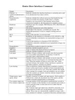
Figure 4 illustrates four routers connected to an NBMA network. Within the network are ATM or
SMDS switches necessary for the routers to communicate with each other. Assume that the switches
have virtual circuit connections represented by hops 1, 2, and 3 of the figure. When Router A
attempts to forward an IP packet from the source host to the destination host, NHRP is triggered. On
behalf of the source host, Router A sends an NHRP request packet encapsulated in an IP packet,
which takes three hops across the network to reach Router D, connected to the destination host. After
receiving a positive NHRP reply, Router D is determined to be the “NBMA next hop,” and Router A
sends subsequent IP packets for the destination to Router D in one hop.
Figure 4 Next Hop Resolution Protocol (NHRP)
With NHRP, once the NBMA next hop is determined, the source either starts sending data packets
to the destination (in a connectionless NBMA network such as SMDS) or establishes a virtual circuit
connection to the destination with the desired bandwidth and quality of service (QOS) characteristics
(in a connection-oriented NBMA network such as ATM).
Router D
Source
host
Router C
Router A
Router B
IP
NHRP
Hop 1
Hop 2
Hop 3
Subsequent
IP packets
NBMA network
NBMA next hop
Destination
host
S3229
Configure Address Resolution Methods
Configuring IP Addressing P1C-17
Other address resolution methods can be used while NHRP is deployed. IP hosts that rely upon the
LIS (Logical IP Subnet) model might require ARP servers and services over NBMA networks, and
deployed hosts might not implement NHRP, but might continue to support ARP variations. NHRP
is designed to eliminate the suboptimal routing that results from the LIS model, and can be deployed
with existing ARP services without interfering with them.
NHRP is used to facilitate building a virtual private network. In this context, a virtual private network
consists of a virtual Layer 3 network that is built on top of an actual Layer 3 network. The topology
you use over the virtual private network is largely independent of the underlying network, and the
protocols you run over it are completely independent of it.
Connected to the NBMA network are one or more stations that implement NHRP, and are known as
Next Hop Servers. All routers running Release 10.3 or later are capable of implementing NHRP and,
thus, can act as Next Hop Servers.
Each Next Hop Server serves a set of destination hosts, which might or might not be directly
connected to the NBMA network. Next Hop Servers cooperatively resolve the NBMA next hop
addresses within their NBMA network. In addition to NHRP, Next Hop Servers typically participate
in protocols used to disseminate routing information across (and beyond the boundaries of) the
NBMA network, and might support ARP service also.
A Next Hop Server maintains a “next-hop resolution” cache, which is a table of network layer
address to NBMA address mappings. The table is created from information gleaned from NHRP
register packets, extracted from NHRP request or reply packets that traverse the Next Hop Server as
they are forwarded, or through other means such as ARP and preconfigured tables.
Protocol Operation
NHRP requests traverse one or more hops within an NBMA subnetwork before reaching the station
that is expected to generate a response. Each station (including the source station) chooses a
neighboring Next Hop Server to forward the request to. The Next Hop Server selection procedure
typically involves performing a routing decision based upon the network layer destination address
of the NHRP request. Ignoring error situations, the NHRP request eventually arrives at a station that
generates an NHRP reply. This responding station either serves the destination, is the destination
itself, or is a client that specified it should receive NHRP requests when it registered with its server.
The responding station generates a reply using the source address from within the NHRP packet to
determine where the reply should be sent.
NHRP Configuration Task List
To configure NHRP, perform the tasks described in the following sections. The first task is required,
the remainder are optional.
•
Enable NHRP on an Interface
•
Configure a Station’s Static IP-to-NBMA Address Mapping
•
Statically Configure a Next Hop Server
•
Configure NHRP Authentication
•
Control NHRP Rate
•
Suppress Forward and Reverse Record Options
•
Specify the NHRP Responder Address
•
Change the Time Period NBMA Addresses Are Advertised as Valid
•
Configure a GRE Tunnel for Multipoint Operation
P1C-18 Network Protocols Configuration Guide, Part 1
Configure Address Resolution Methods
Enable NHRP on an Interface
To enable NHRP for an interface on a router, perform the following task in interface configuration
mode. In general, all NHRP stations within a logical NBMA network must be configured with the
same network identifier.
See the “Logical NBMA Example” section and the “NHRP over ATM Example” section at the end
of this chapter for examples of enabling NHRP.
Configure a Station’s Static IP-to-NBMA Address Mapping
To participate in NHRP, a station connected to an NBMA network should be configured with the IP
and NBMA addresses of its Next Hop Server(s). The format of the NBMA address depends on the
medium you are using. For example, ATM uses an NSAP address, Ethernet uses a MAC address,
and SMDS uses an E.164 address.
These Next Hop Servers may also be the stations’s default or peer routers, so their addresses can be
obtained from the station’s network layer forwarding table.
If the station is attached to several link layer networks (including logical NBMA networks), the
station should also be configured to receive routing information from its Next Hop Server(s)and peer
routers so that it can determine which IP networks are reachable through which link layer networks.
To configure static IP-to-NBMA address mapping on a station (host or router), perform the following
task in interface configuration mode:
Statically Configure a Next Hop Server
A Next Hop Server normally uses the network layer forwarding table to determine where to forward
NHRP packets, and to find the egress point from an NBMA network. A Next Hop Server may
alternately be statically configured with a set of IP address prefixes that correspond to the IP
addresses of the stations it serves, and their logical NBMA network identifiers.
To statically configure a Next Hop Server, perform the following task in interface configuration
mode:
To configure multiple networks that the Next Hop Server serves, repeat the ip nhrp nhs command
with the same Next Hop Server address, but different IP network addresses. To configure additional
Next Hop Servers, repeat the ip nhrp nhs command.
Task Command
Enable NHRP on an interface. ip nhrp network-id number
Task Command
Configure static IP-to-NBMA address mapping. ip nhrp map ip-address nbma-address
Task Command
Statically configure a Next Hop Server. ip nhrp nhs nhs-address [net-address [netmask]]
Configure Address Resolution Methods
Configuring IP Addressing P1C-19
Configure NHRP Authentication
Configuring an authentication string ensures that only routers configured with the same string can
intercommunicate using NHRP. Therefore, if the authentication scheme is to be used, the same string
must be configured in all devices configured for NHRP on a fabric. To specify the authentication
string for NHRP on an interface, perform the following task in interface configuration mode:
Control NHRP Rate
There are three ways to control NHRP:
•
Trigger NHRP by IP Packets
•
Trigger NHRP on a Per-Destination Basis
•
Control the NHRP Packet Rate
These methods are described in this section.
Trigger NHRP by IP Packets
You can specify an IP access list that is used to decide which IP packets can trigger the sending of
NHRP requests. By default, all non-NHRP packets trigger NHRP requests. To limit which IP packets
trigger NHRP requests, define an access list and then apply it to the interface.
To define an access list, perform one of the following tasks in global configuration mode:
Then apply the IP access list to the interface by performing the following task in interface
configuration mode:
Task Command
Specify an authentication string. ip nhrp authentication string
Task Command
Define a standard IP access list. access-list access-list-number {deny | permit}
source [source-wildcard]
Define an extended IP access list. access-list access-list-number {deny | permit}
protocol source source-wildcard destination
destination-wildcard [precedence precedence][tos
tos] [established] [log]
Task Command
Specify an IP access list that controls NHRP
requests.
ip nhrp interest access-list-number
P1C-20 Network Protocols Configuration Guide, Part 1
Configure Address Resolution Methods
Trigger NHRP on a Per-Destination Basis
By default, when the software attempts to transmit a data packet to a destination for which it has
determined that NHRP can be used, it transmits an NHRP request for that destination. You can
configure the system to wait until a specified number of data packets have been sent to a particular
destination before NHRP is attempted. To do so, perform the following task in interface
configuration mode:
Control the NHRP Packet Rate
By default, the maximum rate at which the software sends NHRP packets is 5 packets per
10 seconds. The software maintains a per interface quota of NHRP packets (whether generated
locally or forwarded) that can be transmitted. To change this maximum rate, perform the following
task in interface configuration mode:
Suppress Forward and Reverse Record Options
To dynamically detect link-layer filtering in NBMA networks (for example, SMDS address screens),
and to provide loop detection and diagnostic capabilities, NHRP incorporates a Route Record in
requests and replies. The Route Record options contain the network (and link layer) addresses of all
intermediate Next Hop Servers between source and destination (in the forward direction) and
between destination and source (in the reverse direction).
By default, forward record options and reverse record options are included in NHRP request and
reply packets. To suppress the use of these options, perform the following task in interface
configuration mode:
Specify the NHRP Responder Address
If an NHRP requestor wants to know which Next Hop Server generates an NHRP reply packet, it
can request that information by including the responder address option in its NHRP request packet.
The Next Hop Server that generates the NHRP reply packet then complies by inserting its own IP
address in the NHRP reply. The Next Hop Server uses the primary IP address of the specified
interface.
To specify which interface the Next Hop Server uses for the NHRP responder IP address, perform
the following task in interface configuration mode:
Task Command
Specify how many data packets are sent to a
destination before NHRP is attempted.
ip nhrp use usage-count
Task Command
Change the NHRP packet rate per interface. ip nhrp max-send pkt-count every interval
Task Command
Suppress forward and reverse record options. no ip nhrp record
Task Command
Specify which interface the Next Hop Server uses
to determine the NHRP responder address.
ip nhrp responder type number
Enable IP Routing
Configuring IP Addressing P1C-21
If an NHRP reply packet being forwarded by a Next Hop Server contains that Next Hop Server’s
own IP address, the Next Hop Server generates an Error Indication of type “NHRP Loop Detected”
and discards the reply.
Change the Time Period NBMA Addresses Are Advertised as Valid
You can change the length of time that NBMA addresses are advertised as valid in positive and
negative NHRP responses. In this context, advertised means how long the Cisco IOS software tells
other routers to keep the addresses it is providing in NHRP responses. The default length of time for
each response is 7,200 seconds (2 hours). To change the length of time, perform the following task
in interface configuration mode:
Configure a GRE Tunnel for Multipoint Operation
You can enable a generic routing encapsulation (GRE) tunnel to operate in multipoint fashion. A
tunnel network of multipoint tunnel interfaces can be thought of as an NBMA network. To configure
the tunnel, perform the following tasks in interface configuration mode:
The tunnel key should correspond to the NHRP network identifier specified in the ip nhrp
network-id command. See the “NHRP on a Multipoint Tunnel Example” section at the end of this
chapter for an example of NHRP configured on a multipoint tunnel.
Enable IP Routing
IP routing is automatically enabled in the Cisco IOS software. If you choose to set up the router to
bridge rather than route IP datagrams, you must disable IP routing. To reenable IP routing if it has
been disabled, perform the following task in global configuration mode:
When IP routing is disabled, the router will act as an IP end host for IP packets destined for or
sourced by it, whether or not bridging is enabled for those IP packets not destined for the device. To
reenable IP routing, use the ip routing command.
Task Command
Specify the number of seconds that NBMA
addresses are advertised as valid in positive or
negative NHRP responses.
ip nhrp holdtime seconds-positive
[seconds-negative]
Task Command
Enable a GRE tunnel to be used in multipoint
fashion.
tunnel mode gre ip multipoint
Configure a tunnel identification key. tunnel key key-number
Task Command
Enable IP routing. ip routing
P1C-22 Network Protocols Configuration Guide, Part 1
Enable IP Routing
Routing Assistance When IP Routing Is Disabled
The Cisco IOS software provides three methods by which the router can learn about routes to other
networks when IP routing is disabled and the device is acting as an IP host. These methods are
described in the sections that follow:
•
Proxy ARP
•
Default Gateway (also known as default router)
•
ICMP Router Discovery Protocol (IRDP)
When IP routing is disabled, the default gateway feature and the router discovery client are enabled,
and proxy ARP is disabled. When IP routing is enabled, the default gateway feature is disabled and
you can configure proxy ARP and the router discovery servers.
Proxy ARP
The most common method of learning about other routes is by using proxy ARP. Proxy ARP, defined
in RFC 1027, enables an Ethernet host with no knowledge of routing to communicate with hosts on
other networks or subnets. Such a host assumes that all hosts are on the same local Ethernet, and that
it can use ARP to determine their hardware addresses.
Under proxy ARP, if a device receives an ARP Request for a host that is not on the same network as
the ARP Request sender, the Cisco IOS software evaluates whether it has the best route to that host.
If it does, the device sends an ARP Reply packet giving its own Ethernet hardware address. The host
that sent the ARP Request then sends its packets to the device, which forwards them to the intended
host. The software treats all networks as if they are local and performs ARP requests for every IP
address. This feature is enabled by default. If it has been disabled, see the section “Enable Proxy
ARP” earlier in this chapter.
Proxy ARP works as long as other routers support it. Many other routers, especially those loaded
with host-based routing software, do not support it.
Default Gateway
Another method for locating routes is to define a default router (or gateway). The Cisco IOS software
sends all nonlocal packets to this router, which either routes them appropriately or sends an IP
Control Message Protocol (ICMP) redirect message back, telling it of a better route. The ICMP
redirect message indicates which local router the host should use. The software caches the redirect
messages and routes each packet thereafter as efficiently as possible. The limitations of this method
are that there is no means of detecting when the default router has gone down or is unavailable, and
there is no method of picking another device if one of these events should occur.
To set up a default gateway for a host, perform the following task in global configuration mode:
To display the address of the default gateway, use the show ip redirects EXEC command.
Task Command
Set up a default gateway (router). ip default-gateway ip-address
Enable IP Routing
Configuring IP Addressing P1C-23
ICMP Router Discovery Protocol (IRDP)
The Cisco IOS software provides a third method, called router discovery, by which the router
dynamically learns about routes to other networks using the ICMP Router Discovery Protocol
(IRDP). IRDP allows hosts to locate routers. When operating as a client, router discovery packets
are generated. When operating as a host, router discovery packets are received. Our IRDP
implementation fully conforms to the router discovery protocol outlined in RFC 1256.
The software is also capable of wire-tapping Routing Information Protocol (RIP) and Interior
Gateway Routing Protocol (IGRP) routing updates and inferring the location of routers from those
updates. The server/client implementation of router discovery does not actually examine or store the
full routing tables sent by routing devices, it merely keeps track of which systems are sending such
data.
You can configure the four protocols in any combination. When possible, we recommend that you
use IRDP because it allows each router to specify both a priority and the time after which a device
should be assumed down if no further packets are received. Devices discovered using IGRP are
assigned an arbitrary priority of 60. Devices discovered through RIP are assigned a priority of 50.
For IGRP and RIP, the software attempts to measure the time between updates, and assumes that the
device is down if no updates are received for 2.5 times that interval.
Each device discovered becomes a candidate for the default router. The list of candidates is scanned
and a new highest-priority router is selected when any of the following events occur:
•
When a higher-priority router is discovered (the list of routers is polled at 5-minute intervals).
•
When the current default router is declared down.
•
When a TCP connection is about to time out because of excessive retransmissions. In this case,
the server flushes the ARP cache and the ICMP redirect cache, and picks a new default router in
an attempt to find a successful route to the destination.
Enable IRDP Processing
The only required task for configuring IRDP routing on a specified interface is to enable IRDP
processing on an interface. Perform the following task in interface configuration mode:
Change IRDP Parameters
When you enable IRDP processing, the default parameters will apply. You can optionally change any
of these IRDP parameters. Perform the following tasks in interface configuration mode:
Task Command
Enable IRDP processing on an interface. ip irdp
Task Command
Send IRDP advertisements to the all-systems
multicast address (224.0.0.1) on a specified
interface.
ip irdp multicast
Set the IRDP period for which advertisements are
valid.
ip irdp holdtime seconds
Set the IRDP maximum interval between
advertisements.
ip irdp maxadvertinterval seconds
Set the IRDP minimum interval between
advertisements.
ip irdp minadvertinterval seconds
Set a device’s IRDP preference level. ip irdp preference number