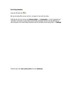
Configure an IP Helper Address for DHCP
Bạn đang xem bản rút gọn của tài liệu. Xem và tải ngay bản đầy đủ của tài liệu tại đây (54.11 KB, 15 trang )
Lab 6.3.5: Configure an IP Helper Address for DHCP
Accounting
VLAN10
10.1.10.0/24
Marketing
VLAN20
10.1.20.0/24
FEC Trunk
802.1q
10.1.1.0/24
Native
VLAN1
Engineering
VLAN30
10.1.30.0/24
10.1.30.2
Engineering Workstation
ALSwitch
2900XL
10.1.1.251/24
ISP
Lo0
200.200.2.0/24
DLSwitch
4006
10.1.1.250/24
Internet
VLAN2
10.1.2.0/24
CORP
2600
10.1.2.1/24
Serial 0/1 DCE
200.200.1.0/24
Serial 0/1 DTE
10.1.1.1/24
DLRouter
EZ-IP
VLANS 10,20,30
IP Helper
VLANS 10,20,30
Objective:
Configure an IP helper address pointing to a DHCP enabled router
Scenario:
Current Environment
Your network equipment currently includes a 4006 Core switch, 2900XL access switch and a 2600
Internet router. Your network is segmented into five functional VLANs for better network
management. VLANs include “Accounting”, “Marketing”, “Engineering”, and “Internet” for the users
and “default” used for the native VLAN network management. Inter-VLAN routing has been
implemented using a Layer-3 routing switch module for the 4006 to allow individuals and servers on
your Virtual LANs to exchange information. VLAN-trunking to the 2900XL has been implemented
over a Fast-EtherChannel group. EIGRP is configured between the 2600 series router and the
4006 Layer-3 module and VLAN domain pruning is enabled on the DLSwitch for trunk optimization.
Enhancement
Desktop support staffs report that static IP addressing is cumbersome and inefficient. They have
requested that as the network engineer you implement dynamic addressing with DHCP. After
gaining management approval, you decide to implement dynamic addressing for VLANs 10, 20 and
30 only, as the others do not require it. Additionally, the first 25 addresses in each range should be
excluded from the scopes for servers and printers. You select the 2600 to support the scopes as
your current Version IOS on DLRouter does not support DHCP. Hence, each VLAN interface must
relay requests to the Internet 2600 for fulfillment of DHCP requests. Your VTP and subnetwork
information are as follows:
Design:
Switched Network VTP Configuration Information:
Switch VTP Domain VTP Mode VTP Pruning
DLSwitch CORP Server Enabled
ALSwitch CORP Client N/A
VLAN Configuration Information:
VLAN
ID
VLAN
Name
VLAN
Subnet
VLAN
Gateway
1 Default “Native” 10.1.1.0/24 10.1.1.1
2 Internet 10.1.2.0/24 10.1.2.1
10 Accounting 10.1.10.0/24 10.1.10.1
20 Marketing 10.1.20.0/24 10.1.20.1
30 Engineering 10.1.30.0/24 10.1.30.1
Switch VLAN Port Assignments
Switch VLAN
1
VLAN
2
VLAN
10
VLAN
20
VLAN
30
Trunk
DLSwitch 6-18 5 19-24 25-30 31-34 3,4
ALSwitch 3 N/A 4-6 7-9 10-12 1,2
Cisco 4006 DLRouter Interface Configuration Information:
Interface IP Address VLAN
PortChannel 1.1 10.1.1.1/24 Native 1
PortChannel 1.2 10.1.2.1/24 2
PortChannel 1.10 10.1.10.1/24 10
PortChannel 1.20 10.1.20.1/24 20
PortChannel 1.30 10.1.30.1/24 30
Cisco 2600 Internet Router Interface Configuration Information:
Interface IP Address NAT
Serial 0/0 None N/A
Serial 0/1 200.200.1.2/24 Outside
FastEthernet 0/0 10.1.2.2/24 Inside
FastEthernet 0/1 None N/A
Notes:
Lab Tasks:
If you completed the last lab (Configure RSM to External Router) then you are ready to implement
the DHCP VLAN processes on the same network environment so skip to step 18. Step 18 will
again have you simply verify that all components are functioning properly before we begin. If you
have started this lab without the prior completion of the previous lab then simply begin at step 1.
For expedited purposes we will not expend time on task explanations through step 18 as we have
already done that in previous labs thereby avoiding duplication.
1. Cable the lab as shown in the diagram.
2. The first device to be configured will be the distribution layer switch DLSwitch.
Switch> (enable) clear config all
Switch> (enable) reset
3. Configure the DLSwitch with the following information:
a. Establish switch name and passwords. We will use “cisco” throughout this lab for all
passwords.
Switch> (enable) set system name DLSwitch>
DLSwitch> (enable) set enablepass <enter>
DLSwitch> (enable) set password <enter>
* You will be prompted to enter and confirm the password
b. Configure VTP information on the 4006 switch.
DLSwitch> (enable) set vtp domain CORP
DLSwitch> (enable) set vtp mode server
c. Set switch IP address information and gateway.
DLSwitch> (enable) set interface sc0 up
DLSwitch> (enable) set interface sc0 1 10.1.1.11/255.255.255.0
10.1.1.255
DLSwitch> (enable) set ip route 0.0.0.0/0.0.0.0 10.1.1.1
d. Create the port channel groups.
DLSwitch> (enable) set port channel 2/1-2 156
DLSwitch> (enable) set port channel 2/3-4 157
e. Now we need to prepare these interfaces for trunking.
DLSwitch> (enable) set trunk 2/1 nonegotiate dot1q 1-1005
DLSwitch> (enable) set trunk 2/2 nonegotiate dot1q 1-1005
DLSwitch> (enable) set trunk 2/3 nonegotiate dot1q 1-1005
DLSwitch> (enable) set trunk 2/4 nonegotiate dot1q 1-1005
f. Turn EtherChannel on. .
DLSwitch> (enable) set port channel 2/1-2 mode on
DLSwitch> (enable) set port channel 2/3-4 mode on
* Note: Verify using DLSwitch> (enable) show channel
g. Create corporate VLAN’s.
DLSwitch> (enable) set vlan 1 name default
DLSwitch> (enable) set vlan 10 name Accounting
DLSwitch> (enable) set vlan 20 name Marketing
DLSwitch> (enable) set vlan 30 name Engineering
* Note: Verify using DLSwitch> (enable) show vlan
h. Assign ports to VLANs.
DLSwitch> (enable) set vlan 10 2/19-24
DLSwitch> (enable) set vlan 20 2/25-30
DLSwitch> (enable) set vlan 30 2/31-34
* Note: Verify using DLSwitch> (enable) show vlan
i. Verify complete configuration using DLSwitch> (enable) show config.
4. The next device to be configured will be the access layer switch ALSwitch.
Switch#show vlan
Switch#show vtp stat
5. Clear your NVRAM and reload.
Switch#clear start
Switch#reload
Note: If asked to save system information select “N”
6. Now check VLAN and VTP information again.
Switch#show vlan
Switch#show vtp stat
7. Configure ALSwitch with the following information:
a. Configure VTP trunking information.
Switch#vlan database
Switch(vlan)#vtp client
Switch(vlan)#vtp domain CORP
Switch(vlan)#exit
b. Verify VTP information.
Switch#show vtp stat
c. Configure the hostname ALSwitch on the 29000XL switch.
Switch(config)#hostname ALSwitch
d. Configure the privileged mode password. ALL passwords for this lab will be “cisco”
lower case.
ALSwitch(config)#enable password cisco
e. Configure Fast EtherChannel port group and trunking.
ALSwitch(config)#interface FastEthernet0/1
ALSwitch(config-if)#port group 1
ALSwitch(config-if)#switchport mode trunk
ALSwitch(config-if)#switchport trunk encapsulation dot1q
ALSwitch(config)#interface FastEthernet0/2
ALSwitch(config-if)#port group 1
ALSwitch(config-if)#switchport mode trunk
ALSwitch(config-if)#switchport trunk encapsulation dot1q
f. Add ports to VLANs and implement spanning-tree PortFast. Here we are configuring
the device connection parameters.
ALSwitch(config)#interface FastEthernet0/3
ALSwitch(config-if)#switchport access vlan 1
ALSwitch(config-if)#spanning-tree portfast
ALSwitch(config)#interface FastEthernet0/4
ALSwitch(config-if)#switchport access vlan 10
ALSwitch(config-if)#spanning-tree portfast
ALSwitch(config)#interface FastEthernet0/5
ALSwitch(config-if)#switchport access vlan 10
ALSwitch(config-if)#spanning-tree portfast
ALSwitch(config)#interface FastEthernet0/6
ALSwitch(config-if)#switchport access vlan 10
ALSwitch(config-if)#spanning-tree portfast
ALSwitch(config)#interface FastEthernet0/7
ALSwitch(config-if)#switchport access vlan 20
ALSwitch(config-if)#spanning-tree portfast
ALSwitch(config)#interface FastEthernet0/8
ALSwitch(config-if)#switchport access vlan 20
ALSwitch(config-if)#spanning-tree portfast
ALSwitch(config)#interface FastEthernet0/9
ALSwitch(config-if)#switchport access vlan 20
ALSwitch(config-if)#spanning-tree portfast
ALSwitch(config)#interface FastEthernet0/10
ALSwitch(config-if)#switchport access vlan 30
ALSwitch(config-if)#spanning-tree portfast
ALSwitch(config)#interface FastEthernet0/11
ALSwitch(config-if)#switchport access vlan 30
ALSwitch(config-if)#spanning-tree portfast
ALSwitch(config)#interface FastEthernet0/12
ALSwitch(config-if)#switchport access vlan 30
ALSwitch(config-if)#spanning-tree portfast
g. Configure VLAN1 management interface IP address and default gateway for the
switch.
ALSwitch(config)#ip default-gateway 10.1.1.1
ALSwitch(config)#interface VLAN1
ALSwitch(config-if)#ip address 10.1.1.12 255.255.255.0
h. Configure telnet interface password.
ALSwitch(config)#line vty 0 4
ALSwitch(config-line)#password cisco
ALSwitch(config-line)#login
8. The next device to be configured will be the distribution layer router DLRouter.
DLSwitch> (enable) session 2
Router#clear start
Router#reload
Note: If asked to save system information select “N”
After the card reset then go back into it:
DLSwitch> (enable) session 2
9. Configure the DLRouter with the following information:
a. Configure the hostname DLRouter on the 4006 L3 module.
Router(config)#hostname DLRouter
b. Configure the privileged mode password.
DLRouter(config)#enable password cisco
c. Configure the VLAN interface addressing and trunking information.
DLRouter(config)#interface Port-channel1
DLRouter(config-if)#ip address 10.1.1.1 255.255.255.0
DLRouter(config-if)#no shutdown
DLRouter(config)#interface Port-channel1.10
DLRouter(config-if)#encapsulation dot1Q 10
DLRouter(config-if)#ip address 10.1.10.1 255.255.255.0
DLRouter(config)#interface Port-channel1.20
DLRouter(config-if)#encapsulation dot1Q 20
DLRouter(config-if)#ip address 10.1.20.1 255.255.255.0
DLRouter(config)#interface Port-channel1.30
DLRouter(config-if)#encapsulation dot1Q 30
DLRouter(config-if)#ip address 10.1.30.1 255.255.255.0