Traffic Shaping and Policing
Bạn đang xem bản rút gọn của tài liệu. Xem và tải ngay bản đầy đủ của tài liệu tại đây (4.69 MB, 104 trang )
4
Traffic Shaping and
Policing
Overview
This module describes for the QoS mechanisms that are used to limit the available
bandwidth to traffic classes. It discusses two options—traffic policing and traffic
shaping. Committed Access Rate (CAR) is discussed as a mechanism to provide
traffic policing. Generic Traffic Shaping (GTS) and Frame Relay Traffic Shaping
(FRTS) are discussed as traffic shaping mechanisms.
It includes the following topics:
n Traffic Shaping and Policing
n Generic Traffic Shaping
n Frame Relay Traffic Shaping
n Committed Access Rate
Objectives
Upon completion of this module, you will be able to perform the following tasks:
n Describe and configure Generic Traffic Shaping (GTS)
n Describe and configure Frame Relay Traffic Shaping (FRTS)
n Describe and configure Committed Access Rate (CAR)
n Identify other mechanisms that support traffic shaping and policing (Class-
based Policing and Class-based Shaping)
4-2 IP QoS Traffic Shaping and Policing Copyright 2001, Cisco Systems, Inc.
Traffic Shaping and Policing
Overview
The lesson introduces mechanisms for traffic policing and traffic shaping.
Committed Access Rate (CAR), Generic Traffic Shaping (GTS) and Frame Relay
Traffic Shaping (FRTS) are introduced in this section.
Objectives
Upon completion of this lesson, you will be able to perform the following tasks:
n Describe the need for implementing traffic policing and shaping mechanisms
n List traffic policing and shaping mechanisms available in Cisco IOS
n Describe the benefits and drawbacks of traffic shaping and policing
mechanisms
Copyright 2001, Cisco Systems, Inc. IP QoS Traffic Shaping and Policing 4-3
© 2001, Cisco Systems, Inc. IP QoS Traffic Shaping and Policing-5
Traffic Shaping and Policing
Traffic Shaping and Policing
• Traffic Shaping and Policing mechanisms are used to rate-limit
traffic classes
• They have to be able to classify packets and meter their rate of
arrival
• Traffic Shaping delays excess packets to stay within the rate
limit
• Traffic Policing typically drops excess traffic to stay within the
limit; alternatively it can remark excess traffic
Classifier Marker
Dropper
Meter
Traffic
stream
Both shaping and policing mechanisms are used in a network to control the rate at
which traffic is admitted into the network. Both mechanisms use classification, so
they can differentiate traffic. They also use metering to measure the rate of traffic
and compare it to the configured shaping or policing policy.
The difference between shaping and policing can be described in terms of their
rate-limiting implementation:
n Shaping meters the traffic rate and delays excessive traffic so that it stays
within the desired rate limit. With shaping, traffic bursts are smoothed out
producing a steadier flow of data. Reducing traffic bursts helps reduce
congestion in the core of the network.
n Policing drops excess traffic in order to control traffic flow within specified
limits. Policing does not introduce any delay to traffic that conforms to traffic
policies. It can however, cause more TCP retransmissions, because traffic in
excess of specified limits is dropped.
4-4 IP QoS Traffic Shaping and Policing Copyright 2001, Cisco Systems, Inc.
© 2001, Cisco Systems, Inc. IP QoS Traffic Shaping and Policing-6
Why Use Rate Limiting
Why Use Rate Limiting
• To handle congestion at ingress to ATM/FR
network with asymmetric link bandwidths
• To limit access to resources when high-
speed access is used but not desired
• To limit certain applications or classes
• To implement a virtual TDM system
Rate limiting is typically used to satisfy one of the following requirements:
n Prevent and manage congestion in ATM and Frame Relay networks, where
asymmetric bandwidths are used along the traffic path. This prevents the
layer-2 network from dropping large amounts of traffic by differentiately
dropping excess traffic at ingress to the ATM or Frame Relay networks based
on Layer-3 information (for example: IP precedence, DSCP, access list,
protocol type, etc.)
n Limit the access rate on an interface when high-speed physical infrastructure
is used in transport, but sub-rate access is desired.
n Engineer bandwidth so that traffic rates to certain applications or classes of
traffic follow a specified traffic-rate policy.
n Implement a virtual TDM system, where an IP network is used, but has the
bandwidth characteristics of a TDM system (that is, fixed maximum available
bandwidth). Inbound and outbound policing can, for example, be used on one
router to split a single point-to-point link into two or more virtual point-to-point
links by assigning a portion of the bandwidth to each class, thus preventing any
class from monopolizing the link in either direction.
Copyright 2001, Cisco Systems, Inc. IP QoS Traffic Shaping and Policing 4-5
© 2001, Cisco Systems, Inc. IP QoS Traffic Shaping and Policing-7
Typical Traffic Shaping or
Policing Applications
Typical Traffic Shaping or
Policing Applications
Low-speed
link
High-speed
link
Output interface is
not congested
queuing and WRED
do not work
Congestion in WAN
network results in
non-intelligent layer-
2 drops
Server
Farm
WAN
Internet
FastEthernet
256 kbps
64 kbps
128 kbps
Limiting access to
resources
Implementing a
virtual TDM or
Leased line over a
single physical link
on one side
The figure shows three possible applications of rate-limiting (shaping or policing)
mechanisms. The first picture shows a Layer-2 WAN with unequal link
bandwidths along a Layer-3 path. The ingress (left side) of the network has a high-
speed link available into the Layer-2 backbone, which enables it to send traffic at a
high rate. At the egress side, the sent traffic hits a low-speed link, and the Layer-2
network is forced to drop a large amount of traffic. If traffic were rate-limited at
the ingress, optimal traffic flow occurs, resulting in minimal dropping by the Layer-
2 network.
The second picture shows a hosting farm, which is accessible from the Internet via
a shared link. Depending on the service contract, the hosting provider may offer
different bandwidth guarantees to customers, and may want to limit the resources
a particular server uses. Rate limiting can be used to divide the shared resource
(upstream link) between many servers.
The third example shows the option of implementing virtual leased lines over a
Layer-3 infrastructure, where rate-limited reserved bandwidth is available over a
shared link.
4-6 IP QoS Traffic Shaping and Policing Copyright 2001, Cisco Systems, Inc.
© 2001, Cisco Systems, Inc. IP QoS Traffic Shaping and Policing-8
Shaping vs. Policing
Shaping vs. Policing
• Benefits of Shaping
–Shaping does not drop packets
–Shaping supports interaction with Frame Relay
congestion indication
• Benefits of Policing
–Policing supports marking
–Less buffer usage (shaping requires an additional
queuing system)
A shaper typically delays excess traffic using a buffer, or mechanism, to hold
packets and shape the flow when the data rate of the source is higher than
expected. Traffic shaping smoothes traffic by storing traffic above the configured
rate in a queue. Therefore, shaping increases buffer utilization on a router, but
causes non-deterministic packet delays. Shaping can also interact with a Frame
Relay network, adapting to indications of Layer-2 congestion in the WAN.
A policer typically:
n Drops non-conforming traffic
n Supports marking of traffic
n Is more efficient in terms of memory utilization (no additional buffering of
packets in needed)
n Does not increase buffer usage
Both policing and shaping ensure that traffic does not exceed a bandwidth limit, but
they have different impacts on the traffic:
n Policing drops packets more often, generally causing more retransmissions of
connection-oriented protocols
n Shaping adds variable delay to traffic, possibly causing jitter
Copyright 2001, Cisco Systems, Inc. IP QoS Traffic Shaping and Policing 4-7
© 2001, Cisco Systems, Inc. IP QoS Traffic Shaping and Policing-9
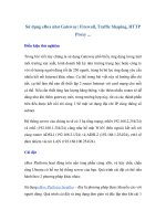
How do Routers Measure Traffic
Rate
How do Routers Measure Traffic
Rate
• Routers use the Token Bucket mathematical model to keep
track of packet arrival rate
• The Token Bucket model is used whenever a new packet is
processed
• The return value is conformor exceed
Bandwidth
Time
Link bandwidth
Rate limit
Exceeding traffic
Conforming Traffic
In order to perform rate limiting, routers must meter (or measure) traffic rates
through their interfaces. To enforce a rate limit, metered traffic is said to:
n Conform to the rate limit, if the rate of traffic is below or equal to the
configured rate limit
n Exceed the rate limit, if the rate of traffic is above the configured rate limit
The metering is usually performed with an abstract model called a token bucket,
which is used when processing each packet. The token bucket can calculate
whether the current packet conforms or exceeds the configured rate limit on an
interface.
4-8 IP QoS Traffic Shaping and Policing Copyright 2001, Cisco Systems, Inc.
© 2001, Cisco Systems, Inc. IP QoS Traffic Shaping and Policing -10
700200
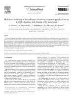
Token Bucket
Token Bucket
500 bytes 500 bytesConform Action
The token bucket is a mathematical model used in a device that regulates the data
flow. The mode has two basic components:
n Tokens: where each token represents the permission to send a fixed number of
bits into the network
n The bucket: which has the capacity to hold a specified amount of tokens
Tokens are put into the bucket at a certain rate by the operating system. Each
incoming packet, if forwarded, takes tokens from the bucket, representing the
packet’s size.
If the bucket fills to capacity, newly arriving tokens are discarded. Discarded
tokens are not available to future packets.
If there are not enough tokens in the bucket to send the packet, the regulator may:
n Wait for enough tokens to accumulate in the bucket (traffic shaping)
n Discard the packet (policing)
The figure shows a token bucket, with the current capacity of 700 bytes. When a
500-byte packet arrives at the interface, its size is compared to the bucket capacity
(in bytes). The packet conforms to the rate limit (500 bytes < 700 bytes), and the
packet is forwarded. 500 tokens are taken out of the token bucket leaving 200
tokens for the next packet.
Copyright 2001, Cisco Systems, Inc. IP QoS Traffic Shaping and Policing 4-9
© 2001, Cisco Systems, Inc. IP QoS Traffic Shaping and Policing -11
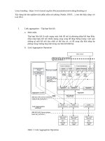
200
Token Bucket
Token Bucket
300 bytes
Exceed Action
300 bytes
When the next packet arrives immediately after the first packet, and no new
tokens have been added to the bucket (which is done periodically), the packet
exceeds the rate limit. The packet size is greater than the current capacity of the
bucket, and the exceed action is performed (drop in the case of pure policing, delay
in the case of shaping).
4-10 IP QoS Traffic Shaping and Policing Copyright 2001, Cisco Systems, Inc.
© 2001, Cisco Systems, Inc. IP QoS Traffic Shaping and Policing -12
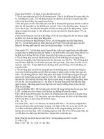
Token Bucket
Token Bucket
• B
c
is normal burst size (specifies sustained rate)
• B
e
is excess burst size (specifies length of burst)
B
c
+ B
e
B
c
of tokens is added
every T
c
[ms]
T
c
= B
c
/ CIR
Time
Link
Utilization
T
c
2*T
c
3*T
c
4*T
c
5*T
c
B
c
B
c
B
c
B
c
B
c
B
c
Link BW
Average BW
(CIR)
B
e
Token bucket implementations usually rely on three parameters: CIR, B
c
and B
e
.
CIR is the Committed Information Rate (also called the committed rate, or the
shaped rate). B
c
is known as the burst capacity. B
e
is known as the excess burst
capacity. T
c
is an interval constant that represents time. A B
c
of tokens are
forwarded without constraint in every T
c
interval.
In the token bucket metaphor, tokens are put into the bucket at a certain rate,
which is B
c
tokens every T
c
seconds. The bucket itself has a specified capacity. If
the bucket fills to capacity (B
c
+ B
e
), it will overflow and therefore newly arriving
tokens are discarded. Each token grants permission for a source to send a certain
number of bits into the network. To send a packet, the regulator must remove,
from the bucket, the number of tokens equal in representation to the packet size.
For example, if 8000 bytes worth of tokens are placed in the bucket every 125
milliseconds, the router can steadily transmit 8000 bytes every 125 milliseconds, if
traffic constantly arrives at the router.
If there is no traffic at all, 8000 bytes per 125 milliseconds get accumulated in the
bucket, up to the maximum size (B
c
+B
e
). One second’s accumulation therefore
collects 64000 bytes worth of tokens, which can be transmitted immediately in the
case of a burst. The upper limit, B
c
+B
e
, defines the maximum amount of data,
which can be transmitted in a single burst, at the line rate.
Note Again, note that the token bucket mechanism used for traffic shaping has both a
token bucket and a queue used to delay packets. If the token bucket did not have
a data buffer, it would be a policer. For traffic shaping, packets that arrive that
cannot be sent immediately (because there are not enough tokens in the bucket)
are delayed in the data buffer.
Copyright 2001, Cisco Systems, Inc. IP QoS Traffic Shaping and Policing 4-11
Although token bucket permits burstiness, traffic bursts are bound. This guarantee
is made so that traffic flow will never send faster than the token bucket's capacity.
In the long-term, this means that the transmission rate will not exceed the
established rate at which tokens are placed in the bucket (the committed rate).
4-12 IP QoS Traffic Shaping and Policing Copyright 2001, Cisco Systems, Inc.
© 2001, Cisco Systems, Inc. IP QoS Traffic Shaping and Policing -13
Traffic Shaping and Policing
Mechanisms
Traffic Shaping and Policing
Mechanisms
• Shaping Mechanisms:
–Generic Traffic Shaping (GTS)
–Frame Relay Traffic Shaping (FRTS)
–Class-based Shaping
• Policing Mechanisms:
–Committed Access Rate (CAR)
–Class-based Policing
There are five token-bucket based rate-limiting methods available in Cisco IOS.
Three methods are shaping mechanisms:
n Generic traffic shaping
n Frame Relay traffic shaping
n Class-based shaping
Two methods are policing mechanisms:
n Committed access rate
n Class-based policing
All these methods are discussed next in specific sections.
Copyright 2001, Cisco Systems, Inc. IP QoS Traffic Shaping and Policing 4-13
Summary
After completing this lesson, you should be able to perform the following tasks:
n Describe the need for implementing traffic policing and shaping mechanisms
n List traffic policing and shaping mechanisms available in Cisco IOS
n Describe the benefits and drawbacks of traffic shaping and policing
mechanisms
Lesson Review
Answer the following questions:
1. How do shaping and policing mechanisms keep track of the traffic rate?
2. Which shaping mechanisms are available with the Cisco IOS software?
3. Which policing mechanisms are available with the Cisco IOS software?
4. What are the main differences between shaping and policing?
4-14 IP QoS Traffic Shaping and Policing Copyright 2001, Cisco Systems, Inc.
Generic Traffic Shaping
Overview
This lesson describes the Generic Traffic Shaping (GTS) mechanism.
Objectives
Upon completion of this lesson, you will be able to perform the following tasks:
n Describe the GTS mechanism
n Describe the benefits and drawbacks of GTS
n Configure GTS on Cisco routers
n Monitor and troubleshoot GTS
Copyright 2001, Cisco Systems, Inc. IP QoS Traffic Shaping and Policing 4-15
© 2001, Cisco Systems, Inc. IP QoS Traffic Shaping and Policing -18
Generic Traffic Shaping
Generic Traffic Shaping
• Can shape multiple classes (classification)
• Can measure traffic rate of individual classes
(metering)
• Delays packets of exceeding classes
(shaping)
Traffic
stream
Classifier Marker
Shaper
Dropper
Meter
Generic Traffic Shaping (GTS) shapes traffic by reducing the outbound traffic flow
to avoid congestion. This is achieved by constraining traffic to a particular bit rate
using the token bucket mechanism. GTS is applied on a per-interface basis and can
use access lists to select the traffic to shape. It works with a variety of Layer-2
technologies, including Frame Relay, ATM, Switched Multi-megabit Data Service
(SMDS) and Ethernet.
As shown in the block diagram, GTS performs three basic functions:
n Classification of traffic, so that different traffic classes can have different
policies applied to them
n Metering, using a token-bucket mechanism, to distinguish between conforming
and exceeding traffic
n Shaping, using buffering, to delay exceeding traffic and shape it to the
configured rate limit
4-16 IP QoS Traffic Shaping and Policing Copyright 2001, Cisco Systems, Inc.
© 2001, Cisco Systems, Inc. IP QoS Traffic Shaping and Policing -19
GTS Building Blocks
GTS Building Blocks
Classifier
Classifier
Classifier
No
No
No
Physical Interface
queue(s)
Shaping
WFQ
Yes
Yes
Yes
Shaping
WFQ
Shaping
WFQ
No
No
No
Yes
Yes
Yes
Forwarder
GTS is implemented as a queuing mechanism, where there are separate WFQ
delay queues implemented for each traffic class. Each WFQ-queue delays packets
until they conform to the rate-limit, and also schedules them according to the WFQ
algorithm. Conforming traffic is then sent to the physical interface.
Arriving packets are first classified into one of the shaping classes. Traffic not
classified into any class is not shaped. Classification can be performed using
access lists.
Once a packet is classified into a shaping class, its size is compared to the amount
of available token in the token bucket of that class. The packet is forwarded to the
main interface queue if there are enough tokens. A number of tokens taken out of
the token bucket is equal to the size of the packet (in bytes).
If, on the other hand, there are not enough tokens to forward the packet, the
packet is buffered in the WFQ system assigned to this shaping class. The router
will then periodically replenish the token bucket and check if there are enough
tokens to forward one or more packets out of the shaping queue. Packets are
scheduled out of the shaping queue according to the WFQ scheduling algorithm.
Copyright 2001, Cisco Systems, Inc. IP QoS Traffic Shaping and Policing 4-17
© 2001, Cisco Systems, Inc. IP QoS Traffic Shaping and Policing -20
GTS Overview
GTS Overview
• GTS is multiprotocol
• GTS uses WFQ as the shaping queue
• GTS can be implemented in combination with
any queuing mechanisms:
–FIFO Queuing
–Priority Queuing (PQ)
–Custom Queuing (CQ)
–Weighted Fair Queuing (WFQ)
• GTS works on output only
The GTS implementation in Cisco IOS supports multiple protocols and works on a
variety of interface types. WFQ is used as the shaping delay queue, providing fair
scheduling within a traffic class. Other queuing strategies (FIFO, PQ, CQ and
WFQ) may be employed after GTS to provide traffic scheduling on the shaped
traffic. Also, GTS only works at the output of an interface.
GTS can be used to shape all outbound traffic on an interface or it can separately
shape multiple classes. Classification is performed using any type of access list
including all non-ip access lists.
4-18 IP QoS Traffic Shaping and Policing Copyright 2001, Cisco Systems, Inc.
© 2001, Cisco Systems, Inc. IP QoS Traffic Shaping and Policing -21
GTS Implementation
GTS Implementation
• The software queue may have no function if
the sum of all shaping rates is less than link
bandwidth
Shaping
Queue
(WFQ)
Software
Queue
(FIFO, PQ,
CQ, WFQ, ...)
Hardware
Queue
(FIFO)
Dispatches
packets at
configured rate
Dispatches
packets at line
rate
Dispatches
packets at line
rate
Bypass the software queue
if it is empty and there is
room in the hardware queue
Packet flow through GTS is implemented using three queues. The first, the shaping
queue, is WFQ-based and shapes traffic according to the specified rate using a
token bucket model. This queue dispatches packets to the software queue, which
may be configured with other queuing mechanisms (PQ, CQ, WFQ or FIFO). If
the software queue is empty, traffic is forwarded directly to the output hardware
queue.
GTS supports distributed implementation on VIP adapters. This offloads traffic
shaping from the route switch processor (RSP) to the Versatile Interface
Processor (VIP), and constructs all of the queues in VIP packet memory. Only IP
traffic can be shaped with dWFQ. Another requirement is that dCEF switching
must be enabled.
Copyright 2001, Cisco Systems, Inc. IP QoS Traffic Shaping and Policing 4-19
© 2001, Cisco Systems, Inc. IP QoS Traffic Shaping and Policing -22
Configuring GTS
Configuring GTS
• Enables traffic shaping of all outbound
(sub)interface traffic
• In IOS versions prior to 11.2(19) and 12.0(4),
optimum switching is disabled on all interfaces if
traffic shaping is enabled on any interface
traffic-shape rate bit-rate [burst-size [excess-
burst-size]]
traffic-shape rate bit-rate [burst-size [excess-
burst-size]]
Router(config-if)#
To enable traffic shaping for outbound traffic on an interface, use the traffic-
shape rate interface configuration command. Of the parameters to be specified,
bit-rate is the only mandatory one. The burst-size and excess-burst-size are
optional.
Generic traffic shaping can be used in all switching paths. Older Cisco IOS
versions may use slower switching paths when GTS is in effect.
4-20 IP QoS Traffic Shaping and Policing Copyright 2001, Cisco Systems, Inc.
© 2001, Cisco Systems, Inc. IP QoS Traffic Shaping and Policing-23
Configuring GTS
Configuring GTS
• Bit rate – average traffic rate in bps (equivalent to
Frame Relay CIR)
• Burst size – amount of traffic sent in a measurement
interval in bits (equivalent to Frame Relay Bc)
Default value: 1/8 of bit rate
traffic-shape rate bit-rate [burst-size [excess-
burst-size]]
traffic-shape rate bit-rate [burst-size [excess-
burst-size]]
Router(config-if)#
Bit rate (in bits per second) is configured as the average traffic rate to which the
traffic should be shaped on the output of the interface.
Burst size (in bits) can be configured to allow for varying levels of allowed
burstiness. That is, traffic, which bursts over the average traffic rate, also
conforms if it falls within the burst rate in an interval. By default, this is set to one
eighth of the average traffic rate, which sets the T
c
at one eighth of a second. This
parameter is equivalent to the Frame Relay B
c
parameter.
Copyright 2001, Cisco Systems, Inc. IP QoS Traffic Shaping and Policing 4-21
© 2001, Cisco Systems, Inc. IP QoS Traffic Shaping and Policing -24
Configuring GTS
Configuring GTS
• Excess-burst-size - amount of excess traffic that
can be sent during the first burst in bps (equivalent
to Frame Relay Be)
Default value: no excess burst
• Measurement interval (Tc) is computed from bit-rate
and burst-size
Tc smaller than 25 ms is rejected, Tc greater than
125 ms is reduced
traffic-shape rate bit-rate [burst-size [excess-
burst-size]]
traffic-shape rate bit-rate [burst-size [excess-
burst-size]]
Router(config-if)#
The excess-burst-size parameter (in bits), equivalent to the Frame Relay B
e
parameter, defines the excess burst of traffic, which can still be sent through the
first noticed burst. By default, there is no excess burst allowed.
The T
c
parameter defines the measurement interval, which is used in the operation
of the token bucket. By default, it is directly computed from the bit rate and the
burst size as B
c
divided by the average bit rate. To ensure proper operation of
shaping, those parameters are bounded to values between 25 and 125 ms.
4-22 IP QoS Traffic Shaping and Policing Copyright 2001, Cisco Systems, Inc.
© 2001, Cisco Systems, Inc. IP QoS Traffic Shaping and Policing -25
Configuring GTS
Configuring GTS
• Shapes outbound traffic matched by the specified access list
• Several traffic-shape group commands can be configured on
the same interface
• The “traffic-shape rate“ and “traffic-shape group“ commands
cannot be mixed on the same interface
• Separate token bucket and shaping queue is maintained for
each traffic-shape group command
• Traffic not matching any access list is not shaped
traffic-shape group access-list bit-rate [burst
[excess-burst]]
traffic-shape group access-list bit-rate [burst
[excess-burst]]
Router(config-if)#
Classification of traffic to be shaped is performed using access lists. To enable
traffic shaping based on a specific access list for outbound traffic on an interface,
use the traffic-shape group interface configuration command. The traffic-shape
group command allows specification of one or more previously defined access
lists to shape traffic on the interface. One traffic-shape group command must be
specified for each access list on the interface.
Cisco IOS uses separate token buckets and shaping queues for each class, as
differentiated by the access list specification. Traffic not matching any access list
bypasses traffic shaping and is immediately sent to the software or hardware
interface queue.
Use the traffic-shape rate command if no classification is needed and shaping
should be applied to all traffic. Remember that the traffic-shape group command
using an IP access list permitting all IP traffic is not equivalent to the traffic-shape
rate command if non-IP traffic is present in the network.
Copyright 2001, Cisco Systems, Inc. IP QoS Traffic Shaping and Policing 4-23
© 2001, Cisco Systems, Inc. IP QoS Traffic Shaping and Policing-26
GTS
Example #1
GTS
Example #1
• ISP wants to sell a service in which a
customer may use all of a E1 line for 30
seconds in a burst, but on a long term
average is limited to 256 kbps
• GTS parameters
–bit-rate: 256000 - output rate is 256000 bps
–burst-size: 32000 the number of bits sent in 125
msec
–excess-burst-size: 61440000 = 2048000 * 30
In the first GTS example, an ISP wants to control the amount of traffic injected
into the Frame Relay WAN by the customer. The SP service uses an E1 line as
the access line, limits the customer to 256 Kbps on the average, but also permits
bursts of up to thirty seconds at the E1 line rate.
The parameters are calculated based on the service requirements. CIR (the
average bit rate) is set at the specified average rate, the burst size is set to one
eighth of the CIR (32000 bits), and the excess burst size reflects the allowed thirty-
second burst at full E1 line rate.
The excess burst size was calculated using the following formula:
1. Each second of transmission at line-speed requires 2 Mbits
2. Thirty second burst therefore requires 30 x 2 Mbits
3. The excess burst size is 30 x 2048000 = 61440000
It takes thirty seconds to empty the token bucket. How long does it take to fill it up
again?
The token bucket is emptied at 2Mbps but it is replenished at 256kbps. It takes
eight times as long to fill it as it does to empty it. Every thirty second burst would,
therefore, require a four-minute silence on the line to accumulate tokens.
4-24 IP QoS Traffic Shaping and Policing Copyright 2001, Cisco Systems, Inc.
© 2001, Cisco Systems, Inc. IP QoS Traffic Shaping and Policing-27
Core
Customer
GTS
Example #1
GTS
Example #1
interface ethernet0/0
traffic-shape rate 256000 32000 61440000
!
interface serial1/0
traffic-shape rate 256000 32000 61440000
interface ethernet0/0
traffic-shape rate 256000 32000 61440000
!
interface serial1/0
traffic-shape rate 256000 32000 61440000
• Since ISP wants to control the total amount of load
the configuration would be done on both the
inbound and outbound interfaces
WAN
The figure shows the router configuration required to implement this service. All
the output traffic is shaped, and the shaping needs to be configured on all customer
edge sites, which will perform admission control using GTS.
Copyright 2001, Cisco Systems, Inc. IP QoS Traffic Shaping and Policing 4-25
© 2001, Cisco Systems, Inc. IP QoS Traffic Shaping and Policing-28
Core
Customer
GTS
Example #2
GTS
Example #2
• The customer wants to be sure that Web
traffic will never use more than 64 kbps
WAN
interface ethernet 0/0
traffic-shape group 101 64000
interface serial 1/0
traffic-shape group 101 64000
!
access-list 101 permit tcp any any eq www
interface ethernet 0/0
traffic-shape group 101 64000
interface serial 1/0
traffic-shape group 101 64000
!
access-list 101 permit tcp any any eq www
In the second example, a customer wants to limit web usage, so that web traffic
never uses more than 64 Kbps on the access link. The router configuration is
shown in the figure, using default parameters for traffic bursts. An access list
defines web traffic as the only shaped traffic. All other traffic bypasses GTS and
can use the full access line bandwidth.