Nghiên cứu nâng cao tính chất sắt điện của màng mỏng PZT chế tạo bằng công nghệ sol gel
Bạn đang xem bản rút gọn của tài liệu. Xem và tải ngay bản đầy đủ của tài liệu tại đây (3.64 MB, 93 trang )
MINISTRY OF EDUCATION AND TRAINING
HANOI UNIVERSITY OF TECHNOLOGY
INTERNATIONAL TRAINING INSTITUTE FOR MATERIALS SCIENCE
..
LE VAN MINH
IMPROVEMENT IN FERROELECTRIC PROPERTY OF PZT THIN
FILMS FABRICATED BY SOL-GEL METHOD
MASTER THESIS OF MATERIALS SCIENCE
BATCH ITIMS - 2006
Supervisor: Associate Prof. Dr. VU NGOC HUNG
Hanoi - 2008
BỘ GIÁO DỤC VÀ ĐÀO TẠO
TRƯỜNG ĐẠI HỌC BÁCH KHOA HÀ NỘI
VIỆN ĐÀO TẠO QUỐC TẾ VỀ KHOA HỌC VẬT LIỆU
LÊ VĂN MINH
NGHIÊN CỨU NÂNG CAO TÍNH CHẤT SẮT ĐIỆN CỦA
MÀNG MỎNG PZT CHẾ TẠO BẰNG CÔNG NGHỆ SOL-GEL
LUẬN VĂN THẠC SĨ KHOA HỌC VẬT LIỆU
KHOÁ ITIMS - 2006
Người hướng dẫn khoa học: PGS. TS. VŨ NGỌC HÙNG
Hà Nội - 2008
ACKNOWLEDGMENTS
My most sincere gratitude belongs to Associate Professor Vu Ngoc Hung
for his continuous support and advice in my research efforts. Moreover, besides
expanding my breadth of ferroelectric knowledge, Prof. Hung has made working
at MEMS Group, International Training Institute for Materials Science (ITIMS),
a true pleasure.
I’d also like to acknowledge IMS, Twente University, MESA+, the
Netherlands, for analyzing and measuring experiment samples including XRD,
AFM, FE-SEM, and TF2000 piezoelectric mode. Special thanks go to PhD.
Nguyen Duc Minh, IMS, Twente, University, MESA+, the Netherlands for
directly implementing these analyses and measurements.
I would also like to express my appreciation to the rest of the MEMS
Group including, Dr. Trinh Quang Thong, Nguyen Van Minh for their daily help
and sincere friendship. Special thanks go to Ms. Bui Thi Huyen, an
undergraduate student, for spending her time to take experiments along with me
and Ms. Vu Thu Hien, who investigated PZT thin film materials in 2007 and
helped establish the scientific kernel and intrigue for completing this current
work.
I would also like to thank ITIMS for making a scientific environment and
facilities. Special thanks go to Dr. Nguyen Anh Tuan and Ms. Le Thanh Hung
for sputtering supports and Dr. Pham Thanh Huy who gave me authority to use
his group’s furnace system.
Finally, I would like to thank my family, especially Mom, Dad, my old
brothers, Le Van Son and Le Van Quang, for their continual love and support as
well as their forbearance of my scientific babble. Without this link to family, I
would become totally consumed by science, which would be a sad life indeed.
Hanoi, September, 2008
LE VAN MINH
VIỆN ĐÀO TẠO QUỐC TẾ VỀ KHOA HỌC VẬT LIỆU
ITIMS KHỐ 2006
Tiêu đề luận văn:
“Nghiên cứu nâng cao tính chất sắt điện của màng mỏng PZT
chế tạo bằng công nghệ sol-gel”
Tác giả:
Lê Văn Minh
Người hướng dẫn:
PGS.TS. Vũ Ngọc Hùng
Người nhận xét: 1.
2.
Tóm tắt:
Màng mỏng PZT [(PbZrxTi1-x)O3], với các tính chất sắt điện, áp điện, hoả
điện nổi bật là một trong những vật liệu được nghiên cứu và ứng dụng trong lĩnh
vực cơng nghệ MEMS, bộ nhớ FeRAM, vv… Tại phịng thí nghiệm MEMS của
Viện ITIMS, màng mỏng PZT cũng đã được triển khai nghiên cứu trong thời gian
vài năm trở lại đây. Bước đầu đã xây dựng được quy trình tổng hợp sol-gel và chế
tạo màng mỏng PZT, xong còn một số hạn chế về tính chất của màng như màng rạn
nứt, nhiều rosettes, độ phân cực điện dư (Pr) nhỏ và điện trường khử phân cực (Ec)
lớn. Mục tiêu của luận văn này là tiến hành những nghiên cứu tiếp theo để tạo ra
màng mỏng PZT có tính chất nâng cao nhằm định hướng trong các ứng dụng của
nhóm MEMS. Trong luận văn này chúng tôi tập trung nghiên cứu nhằm nâng cao
tính chất sắt điện, tránh việc nứt màng và giảm thiểu rosettes của màng mỏng PZT.
Bằng việc tối ưu hóa quy trình sử lý nhiệt, nghiên cứu ảnh hưởng của vật liệu điện
cực đế, và đặc biệt là nghiên cứu màng mỏng PZT dị lớp, tính chất của màng đã
được nâng cao rõ rệt. Màng mỏng PZT(53/47) trên đế Pt(111)/Ti/SiO2/Si có định
hướng ưu tiên (100) đã được chế tạo thành cơng có các thơng số Pr và Ec đạt các giá
trị tương ứng là 12µC/cm2 và Ec là 80kV/cm. Màng PZT(53/47) trên đế oxide
SRO(110)/YSZ/Si có giá trị Pr và Ec tương ứng là 24µC/cm2 và 65kV/cm. Màng
PZT(47/53)/PZT(53/47) cấu trúc dị lớp trên đế SRO/YSZ/Si đã đạt được giá trị Pr
và Ec tương ứng là 28µC/cm2 và 60kV/cm.
Từ khoá: Màng mỏng PZT; Sol-gel; Màng mỏng sắt điện; PZT cấu trúc dị lớp;
Điện cực đế SRO; Điện cực đế Platinum.
INTERNATIONAL TRAINING INSTITUTE FOR MATERIALS SCIENCE
BATCH -2006
Title of Msc. Thesis:
“Improvement in Ferroelectric Property of PZT Thin Films
Fabricated by Sol-gel Method”
Author:
Le Van Minh
Supervisor:
Associate Prof. Dr. Vu Ngoc Hung
Referees:
1.
2.
Abstract:
PZT [(PbZrxTi1-x)O3]thin films having prominent ferroelectric, piezoelectric,
and pyroelectric properties have researched and applied in numerous technological
fields, such as MEMS technology and nonvolatile FeRAM and so on. In recent
years, PZT thin films have been studied and fabricated at MEMS Group,
International Training Institute for Materials Science (ITIMS). At the first stage, the
PZT thin films were synthesized and fabricated. There were, however, some
disadvantages of these thin films, such as, cracked films, many rosettes, small
remanent polarization Pr, and high coercive field Ec. This thesis is the next study
with the aim of fabricating high quality PZT thin films for oriented applications of
MEMS Group. Thus, eliminating crack, reducing rosettes, and improving
ferroelectric property were studied. By optimizing the thermal process and studying
the influence of electrode materials and the heterolayered PZT thin films, the
properties of the PZT thin films have improved significantly. The PZT thin films on
Pt(111)/Ti/SiO2/Si substrates had highly preferred-(001) orientation and the values
of remanent polarization and coercive filed were 12µC/cm2 and 80kV/cm,
respectively. The remanent polarization and the coercive field of the PZT thin films
on SRO(110)/YSZ/Si substrates were 24µC/cm2 and 60kV/cm, respectively. These
values of the heterolayered PZT(47/53)/PZT(53/47) thin films with SRO bottom
electrodes were 28µC/cm2 and 60kV/cm, respectively.
Keywords: PZT thin films; Sol-gel method; Ferroelectric thin films; Heterolayered
PZT thin films; SRO electrode; Platinum electrode.
i
CONTENTS
List of Tables
iv
List of Figures
v
Abbreviations
x
Chapter 1:
FUNDAMENTAL THEORIES OF PZT THIN FILM
1
1.1 Description of Ferroelectricity
1
1.1.1
Description of the Ferroelectric Phase Transition
3
1.1.2
Ferroelectricity in Perovskite Crystals
4
1.1.3
Origin of Spontaneous Polarization
5
1.2 Ferroelectric Domains
7
1.2.1
Domain Walls
1.2.2
Field-Induced Strain Mechanism and Domain Configurations
1.2.3
9
in Ferroelectric Ceramics
10
Extrinsic Contribution to Ferroelectric Properties
12
1.3 PZT thin films
14
1.3.1
Effects of Stress in PZT thin films
16
1.3.2
Effects of Crystalline Orientation on PZT thin films
17
1.4 Ferroelectric Aging
18
1.5 Ferroelectric Fatigue
21
1.5.1
General Discussion of Fatigue Mechanisms
22
1.5.2
Fatigue – Domain Wall Pinning Hypothesis
23
1.5.3
Fatigue- Seed Inhibition Hypothesis
24
ii
1.6 Ferroelectric thin film applications
References:
Chapter 2:
28
31
EXPERIMENTS
36
2.1 General PZT thin film fabrication methods
36
2.1.1
Sputtering
36
2.1.2
PLD: Pulsed Laser Ablation
37
2.1.3
Sol-gel: Solution-Gel
37
2.2 The Sol-Gel Process
39
2.2.1
Sol-gel Route
39
2.2.2
2-MOE based PZT solution preparation
41
2.2.3
Thermal analysis
43
2.3 PZT thin film Fabrication and Processing
46
2.3.1
Substrate Preparation
46
2.3.2
Deposition
50
2.3.3
Thermal Processing
52
References:
Chapter 3:
54
RESULTS AND DISCUSSION
3.1 PZT (53/47) thin films on Pt/Ti/SiO2/Si substrates
55
55
3.1.1
Effect of thermal process
55
3.1.2
Microstructure and XRD patterns
57
3.1.3
Electrical Properties
61
3.2 PZT(53/47) thin films on SRO bottom electrode
3.2.1
Microstructure and XRD patterns
64
66
iii
3.2.2
Electrical properties of PZT(53/47) on SRO/YSZ/Si substrate 68
3.2.3
C-V characteristics
3.3 Heterolayered PZT(47/53)/PZT(53/47) Thin Films
70
71
References:
76
CONCLUSIONS
78
iv
List of Tables
Table 2.1:
Advantages and disadvantages of different deposition
techniques
Table 2.2:
39
Recipe for 0.01mol 2-methoxyethanol (2-MOE) based
PZT (53/47) solution (0.4M).
41
Table 2.2:
Flow diagram for the synthesis of the PZT solution[11-12] 43
Table 3.1:
Remnant polarization and coercive field of PZT thin films
on Pt/Ti/SiO2/Si substrates under different thermal
processes
62
v
List of Figures
Figure 1-1:
Typical hysteresis loops from various ferroelectric
ceramics: paraelectric (a), ferroelectric (b), relaxor (c),
antiferroelectric (d)
Figure 1-2:
2
Soft Mode Description of the Ferroelectric Phase
Transition
3
Figure 1-3:
Illustration of the Perovskite Unit Cell
5
Figure 1-4:
Energy
explanation
of
the
origin
of
spontaneous
polarization
6
Figure 1-5:
Formation of 180o Ferroelectric Domain Walls
9
Figure 1-6:
Strain Energy Relief by 90o Domain Wall Motion
Figure 1-7:
Schematic explanation of the strain change in a
ferroelectric
ceramic
associated
with
the
10
domain
reorientation [11].
Figure 1-8:
Illustration of Dielectric Tunability in Ferroelectric
Materials
Figure 1-9:
13
Phase Diagram of the PbZrO3/PbTiO3 Solid Solution
System
Figure 1-10:
13
15
Illustration of stress induced domain structure in PZT thin
films
17
Figure 1-11:
Aging in Poled Ferroelectric Materials
20
Figure 1-12:
Effect of Aging in Unpoled Ferroelectrics
20
Figure 1-13:
Change in P-E Response as a result of ferroelectric fatigue 21
Figure 1-14:
Domain Wall Pinning Model of Ferroelectric Fatigue
24
vi
Figure 1-15:
Seed Inhibition Model of Ferroelectric Fatigue
Figure 1-16:
AFM assisted Piezo-Response Images of a Fatigued PZT
25
film
26
Figure 1-17:
Overview of typical ferroelectric thin-film applications
28
Figure 1-18:
Example of a (a) sensor and (b) an actuator. A PZT layer is
shown in these examples but it could be a different
piezoelectric layer. The microvalve in (b) is based on
reference [42].
29
Figure 2-1:
Sol-gel System at MEMS Group, ITIMS.
42
Figure 2-2:
DSC and TGA analysis of PZT 2-MOE based sol-gels.
44
Figure 2-3:
Four regions of solid appear as the calcining temperature
increases
Figure 2-4:
45
Schematic showing boundary of stability of a range of
metals with respect to their oxides [5].
48
Figure 2-5:
Unit cell of YSZ material [5]
49
Figure 2-6:
The structure of SRO/YSZ/Si substrate [6]
49
Figure 2-7:
Stages of the spinning process (T0
50
Figure 2-8:
Spinner for depositing PZT solution onto substrates:
Spinner (a), and diagram of spinning rate(b)
51
Figure 2-9:
Flow diagram of Thermal Process
53
Figure 3-1:
Thermal process 1(a): one step of pyrolysis at 300oC for
1min.; thermal process 2(b): two steps of pyrolysis at
300oC for 30 min. and 400oC for 10 min.
55
vii
Figure 3-2:
Micrographs of the PZT thin film fabricated by using
thermal process 1, two-layer thin film (a), and four-layer
thin film (b)
Figure 3-3:
Micrograph of four-layer PZT(53/47) on Pt/Ti/SiO2/Si
fabricated by using the new thermal process
Figure 3-4:
58
The XRD patterns of the PZT films with different mole
excess Pb (a) 5%, (b) 10%, and (c) 20% [15]
Figure 3-7:
58
Cross section SEM image of PZT(53/47) thin film on
Pt/Ti/SiO2/Si
Figure 3-6:
57
Atomic Force Microscopy image of PZT 53/47 thin film
fabricated by using the thermal process 2
Figure 3-5:
56
59
The XRD pattern of the PZT (53/47) thin films on
Pt/Ti/SiO2/Si fabricated by using the thermal process 1(a)
and the new thermal process 2(b).
Figure 3-8:
60
Ferroelectric hysteresis loops of PZT thin films treated by
thermal process 1: (a) at different frequencies (b) at
frequency 1kHz with different applied voltages 5V, 10V,
and 20V [1]
Figure 3-9:
61
Ferroelectric hysteresis loops of PZT thin films treated by
thermal process 2: (a) at different frequencies (b) at
frequency 1kHz with different applied voltages 5V, 10V,
and 20V
Figure 3-10:
62
The capacitance (a) and dielectric constant (b) of PZT thin
films versus applied voltages
63
viii
Figure 3-11:
The
P-E
and
C-V
characteristics
of
PZT(53/47)/Pt/Ti/SiO2/Si
Figure 3-12:
Micrograph of PZT thin films on the SRO/YSZ/Si
substrates
Figure 3-13:
67
XRD pattern of four-layer PZT(53/47) thin film on
SRO/YSZ/Si substrate
Figure 3-16:
66
SEM of four-layer PZT(53/47) thin film on SRO/YSZ/Si
substrate
Figure 3-15:
65
AFM images of four-layer PZT (53/47)thin film on
SRO/YSZ/Si substrate
Figure 3-14:
64
67
Ferroelectric hysteresis loops of PZT/SRO/YSZ/Si thin
films: (a) at different frequencies (b) at different applied
voltages 5V, 10V, and 20V with a frequency 1kHz
Figure 3-17:
P-E loops of PZT on SRO/YSZ/Si and Pt/Ti/SiO2/Si
substrates, at applied voltage 20V, and frequency 1kHz
Figure 3-18:
69
69
C-V and P-E characteristics of PZT (53/47) thin film on
SRO/YSZ/Si substrate at frequency 10kHz and at voltage
10V
Figure 3-19:
The dielectric constant of PZT thin films on SRO and Pt
bottom electrodes depend on applied voltages
Figure 3-20:
71
Illustrate the heterolayers between PZT(47/53)(tetragonal)
and PZT(53/47) (rhombohedral)
Figure 3-21:
70
Cross section SEM images of PZT thin film on
SRO/YSZ/Si substrates: four-layer PZT (53/47) (a) and
73
ix
four-layer PZT(47/53)/PZT( 53/47) heterolayer structure
(b)
Figure 3-22:
AFM images of heterolayered PZT thin film consisting of
alternating PZT(47/53) and PZT(53/47)layers
Figure 3-23:
73
74
P-E hysteresis for PZT thin film on SRO/YSZ/Si
substrates: PZT(53/47) (a), PZT(47/53)/PZT(53/47) (b)
75
x
Abbreviations
AFM
FeRAM
FE-SEM
MEMS
MPB
PZT
XRD
Atomic Force Microscopy
Ferroelectric Random Access Memory
Field Emission – Scanning Electron Microscopy
Micro-Electromechanical Systems
Morphotropic Phase Boundary
Lead Zirconate Titanate (PbZrxTi1-xO3)
X-ray Diffraction
1
Chapter 1:
1.1
FUNDAMENTAL THEORIES OF PZT THIN FILM
Description of Ferroelectricity
Ferroelectric materials are a subclass of pyroelectric crystals, while
pyroelectric crystals are a special class of piezoelectric crystals. Ferroelectrics
are commonly described as non-centrosymmetric materials containing an
electrically re-orientable spontaneous polarization at equilibrium. The
prominent properties of these materials are piezoelectricity, pyroelectricity,
and ferroelectricity.
Piezoelectric effect was discovered by Curie brother in 1880.
Piezoelectricity is a material property that linearly relates applied stresses to
induced dielectric displacements (direct piezoelectric effect) or applied
electric fields to induced strains (converse piezoelectric effect)[1]. A third
rank tensor is necessary to fully describe the piezoelectric response of a
crystal. Neumann’s principle establishes that the symmetry of a crystal’s point
group is reflected in the symmetry of its external properties. Thus, only
materials that lack an inversion point (i.e. are non-centrosymmetric) can
exhibit piezoelectricity. Centrosymmetric materials are incapable of
containing odd-rank tensor properties because the inversion symmetry
produces perfect compensation for such “directional” properties. Of the 32
point groups, 21 lack inversion point symmetry and 20 of these display
piezoelectricity (only the point group 432 fails to be piezoelectric) [2]. Thus,
the non-centrosymmetric crystalline establishes the piezoelectric nature of the
ferroelectric materials.
However, the piezoelectric response does not guarantee the “polar” nature
of a material. In some piezoelectric crystals such as quartz, polar directions
are arranged such that they self-compensate and only exhibit the piezoelectric
2
response under inhomogeneous stresses- not under hydrostatic conditions.
Only 10 of the 20 piezoelectric point groups (those that contain a unique axis
of rotation with no mirror plane perpendicular to it [3]) allow for the existence
of permanent dipoles- that is a unique polar axis [4]. These “polar” materials
will exhibit a hydrostatic piezoelectric response as well as the additional
property of pyroelectricity. In such crystals, temperature changes cause
thermal fluctuations in the basic ionic and electronic forces of the material,
varying the magnitude of the permanent dipole moments within the material.
The pyroelectric effect manifests as a variation in the polarization magnitude
as a result of a temperature change [4]. Pyroelectricity is intrinsically
established in ferroelectrics because of their “spontaneous” polarization.
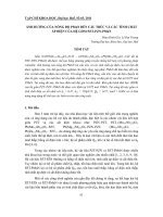
Figure 1-1: Typical hysteresis loops from various ferroelectric ceramics:
paraelectric (a), ferroelectric (b), relaxor (c), antiferroelectric (d)
Yet, materials with a unique polar axis, such as ZnO or GaN, are not
necessarily ferroelectric. The final requirement, a switchable or “reorientable” dipole, is required for the ferroelectric response. Ferroelectricity is
essentially a hysteretic polarizability in response to an applied electric field.
3
As shown in figure 1-1b a plot of polarization vs. electric field has the classic
hysteresis loop shape analogous to the magnetization response of a
ferromagnet. P-E loops can be used as a fingerprint to identify the material.
The typical hysteresis loops obtained for various ferroelectric ceramics are
presented in figure 1-1.
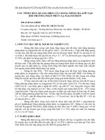
1.1.1 Description of the Ferroelectric Phase Transition
Many approaches can be taken to understand the ferroelectric phase
transition; however, an examination of lattice dynamics is perhaps the most
useful for visualizing the structure-property relationships that occur in the
material. From this viewpoint, a displacive ferroelectric transition occurs if a
transverse optic branch of the phonon spectrum has an instability at the Curie
Figure 1-2: Soft Mode Description of the Ferroelectric Phase Transition:
Dispersion spectrum showing the change in a soft mode phonon when a
material is cooled below the Curie temperature. The “frozen” phonon
vibration (ω=0) in ferroelectric materials creates a set of distortion/dipoles
that oscillate with infinite wavelength (k=0) while anti-ferroelectric materials
have dipoles that oscillate with a wavelength that is twice the unit cell
dimension (k=1/λ=1/2a) [4].
4
temperature. As the instability is approached from high temperatures, this
phonon mode “softens” until its frequency reaches zero and the wavelength
becomes infinite. Thus, at the transition temperature, the soft mode vibration
locks in a displacive distortion which creates the spontaneous polarization
necessary for ferroelectricity. However, this vibrational mode remains easily
activated, providing a significantly large contribution to the dielectric
permittivity than other modes. Figure.1-2 demostrates how soft modes can
create both ferroelectric and anti-ferroelectric behavior (the latter being a nonpolar state with alternating opposite dipoles) [4, 5].
1.1.2 Ferroelectricity in Perovskite Crystals
Ferroelectrics with the perovskite crystal structure are probably the most
important class of ferroelectrics for technological applications. An ideal
perovskite structure is depicted in figure 1-3 and is described as having a
cubic unit cell with A-site cations at the corners, a B-site cation in the center,
and oxygen anions on the six centered faces. This structure is capable of
adjusting through minor distortions to accommodate A and B site cations with
inexact radii sizes to achieve ideal 12-fold and 6-fold respective
coordinations. In the ideal perovskite structure, twice the B-O bond length
(2rB-O)should equal the unit cell dimension (a), while twice the A-O bond
length (2rA-O) should equal the face diagonal (a√2). From this analysis, a
tolerance factor can be derived:
𝑡𝑡𝑓𝑓 =
√2𝑟𝑟𝐴𝐴−𝑂𝑂
2𝑟𝑟𝐵𝐵−𝑂𝑂
(1-1)
where the tolerance factor (tf) should equal 1 for the ideal case. When the Bsite cation is too small for its site (tf>1), such as in BaTiO3 and PbTiO3, this
cation shifts towards an oxygen face, taking on an effective 5-fold
coordination. To accommodate the reduction of the B-O bond length, the unit
5
cell contracts in the plane perpendicular to the shift creating a tetragonal
distortion. Conversely, if the A-site cations are too small (tf<1), the oxygen
octahedron tilts. The octahedron may tilt towards the corners to create a
rhombohedral distortion such as in Zr-rich PZT or towards the edges to create
an orthorhombic distortion such as in the antiferroelectric PbZrO3 [6]. Since
the space group of cubic perovskite (Pm3m) is centrosymmetric, these
distortions are necessary to remove the center of symmetry and stabilize the
existence of permanent dipoles.
Figure 1-3: Illustration of the Perovskite Unit Cell: A drawing of the
undistorted perovskite unit cell with the location of A-site and B-site cations
labeled
Although some technologically important ferroelectrics such as LiNbO3
take on layered structure, the remaining portions of this chapter will focus on
ferroelectricity in perovskite-based materials unless otherwise noted.
1.1.3 Origin of Spontaneous Polarization
In a polar structure, each dipole is influenced by its neighbors. For
simplicity, assuming the dipole moments results from the equal displacement
6
of one kind of ion A relative to the crystal lattice, in which exists a local field,
(Eloc) from the surrounding polarization P to any individual ion A.
𝐸𝐸𝑙𝑙𝑙𝑙𝑙𝑙 = (𝛾𝛾/3𝜀𝜀0 )𝑃𝑃
(1-2)
where 𝛾𝛾 is the Lorentz factor, 𝜀𝜀0 is the permittivity of vacuum.
This local field is the driving force of the ion shift. Thus, the Lorentz
factor is sometimes seen as a measure of the strength of dipole interactions. If
the ionic polarizability of ion is 𝛼𝛼, then the dipole moment of the unit cell is:
𝜇𝜇 = (𝛼𝛼𝛼𝛼/3𝜀𝜀0 )𝑃𝑃
(1-3)
Considering N number of atoms per unit volume, the energy of the dipole
moment is:
𝑊𝑊𝑑𝑑𝑑𝑑𝑑𝑑 = 𝑁𝑁(−𝜇𝜇𝐸𝐸𝑙𝑙𝑙𝑙𝑙𝑙 ) = −(𝑁𝑁𝑁𝑁𝛾𝛾 2 /9𝜀𝜀02 )𝑃𝑃2
(1-4)
When the ions are displaced from their nonpolar equilibrium positions, the
increase of the elastic energy per unit volume is:
𝑊𝑊𝑒𝑒𝑒𝑒𝑒𝑒𝑒𝑒 = 𝑁𝑁[(𝑘𝑘/2)𝑢𝑢2 + (𝐾𝐾/4)𝑢𝑢4 ]
(1-5)
Where u is the ions displacement from their equilibrium positions (u=P/Nq,
where q is the electric charge), k and K are force constants.
The total energy can be expressed as (Figure 1-4 [1]):
𝑘𝑘
𝑊𝑊𝑡𝑡𝑡𝑡𝑡𝑡 = 𝑊𝑊𝑑𝑑𝑑𝑑𝑑𝑑 + 𝑊𝑊𝑒𝑒𝑒𝑒𝑒𝑒𝑒𝑒 = �(2𝑁𝑁𝑞𝑞2) −
(a) Dipole Interaction
𝑁𝑁𝑁𝑁𝛾𝛾2
�9𝜀𝜀02 �
𝐾𝐾
� 𝑃𝑃2 + �(4𝑁𝑁3
(b) Elastic Energy
� 𝑃𝑃4
𝑞𝑞4 )
(1-6)
(c) Total Energy
Figure 1-4: Energy explanation of the origin of spontaneous polarization
(after K. Uchino [7])
7
The first order derivative of the total energy Wtot related to polarization P
shows:
𝜕𝜕𝑊𝑊𝑡𝑡𝑡𝑡𝑡𝑡
Hence,
𝜕𝜕𝜕𝜕
𝑘𝑘
= 𝑃𝑃 �(𝑁𝑁𝑞𝑞2) −
𝑃𝑃2 =
2𝑁𝑁𝑁𝑁𝛾𝛾2
�9𝜀𝜀02 �
𝐾𝐾
� + �(𝑁𝑁3
� 𝑃𝑃3 = 0
𝑞𝑞4 )
��2𝑁𝑁𝑁𝑁𝛾𝛾2 /9𝜀𝜀02 �−(𝑘𝑘/𝑁𝑁𝑞𝑞2 )�
𝐾𝐾/𝑁𝑁3 𝑞𝑞4
(1-7)
(1-8)
From Eq. (1-8), one can see that there are two solutions for P where the total
energy will be minimum. This has been represented in figure 1-4c.
1.2
Ferroelectric Domains
When a perovskite ferroelectric is cooled below Tc, the direction of the
spontaneous polarization is equally probable in all of the crystallographically
equivalent polarization directions – for instance, all six <100> directions for
tetragonal distortions or all eight <111> directions for rhombohedral
distortions. Inevitably, electrical and mechanical boundary conditions limit
the volume over which a particular polarization direction can extend. As a
result, regions of uniformly oriented spontaneous polarizations develop called
domains. Domain walls separate domains with different spontaneous
polarization orientation [5, 8].
Physically, the electrical constraint imposed on the material is a
depolarization field developed from a “surface charge” that results from the
emergence of the spontaneous polarization, because a discontinuity in the
periodic dipole alignment occurs at the surface or at an interface (grain
boundary), an electric field forms due to the uncompensated dipole charges at
this surface (“surface charge”). This field must act in opposition of the
dipoles. Mathematically this situation is expressed using the dielectric
8
displacement vector (D), which describes the surface charge density of the
material:
𝐷𝐷 = 𝜀𝜀0 𝐸𝐸 + 𝑃𝑃
(1-10)
where ε0 is the permittivity of free space (8.8510-12F/m), E is the applied
electric field, and P is the induced polarization of the material, which is also a
function of the electric field:
𝑃𝑃(𝐸𝐸 ) = 𝑃𝑃𝑠𝑠 + 𝜀𝜀0 𝜒𝜒𝜒𝜒
(1-11)
where Ps is the spontaneous polarization and χ is the dielectric susceptibility
[5, 9]. Assuming no charge compensation from outside charges (D=0) and
using the definition of the relative permittivity (dielectric constant) of a
material (εr=1+χ) these expressions become:
𝐸𝐸𝐷𝐷 = −
𝑃𝑃𝑠𝑠
(1-12)
𝜀𝜀0 𝜀𝜀𝑟𝑟
where ED is the depolarization field for spontaneous polarization. The volume
density of energy stored by this field is then given by:
𝑑𝑑𝑑𝑑 = ∫ 𝐸𝐸𝐷𝐷 . 𝑑𝑑𝑑𝑑 = ∫ −
𝑃𝑃𝑠𝑠
𝜀𝜀0 𝜀𝜀𝑟𝑟
𝑑𝑑𝑃𝑃
(1-13)
which implies that the energy associated with the depolarization field inside
the system increase with domain size as:
𝑈𝑈𝑓𝑓𝑓𝑓𝑓𝑓𝑓𝑓𝑓𝑓 ∝
𝑃𝑃𝑠𝑠2
2𝜀𝜀0 𝜀𝜀𝑟𝑟
𝑉𝑉
(1-14)
Where Ufield is the energy and V is the volume of the domain [9]. At some
volume, the increase in energy will make a single domain unstable. To lower
its energy, the domain can split into two domains with different spontaneous
polarization directions. However, the domain wall that separates the two new
domains has an interfacial energy associated with it. The balance of
depolarization field energy and domain wall interfacial energy partially
determines domain size. A similar analysis can be undertaken for strainrelated energies imposed by the lattice distortions undergone at the phase
9
transition. This strain energy also influences domain size, specifically in
ceramic (polycrystalline) ferroelectrics [8, 9].
Immediately after cooling below Tc, the complex electrostatic and
elastic constraints present in a polycrystalline ceramic lead to a complex
domain structure that often exhibits not net polarization direction. Thus, the
ceramic is non-polar (neither piezoelectric nor pyroelectric) until the domains
are aligned with the application of an external electric field (poling) [5, 8].
Because ceramics have randomly oriented grains, the maximum spontaneous
polarization is a fraction of the single-crystal value and has been calculated to
be 0.83, 0.87, and 0.91 for perovskites with tetragonal, rhombohedral, and
orthorhombic distortions respectively (distortions with more available
polarization directions are more accommodating)[8].
1.2.1 Domain Walls
Figure 1-5: Formation of 180o Ferroelectric Domain Walls: Illustration of
how 180o domain wall formation in a tetragonally distorted perovskite
ferroelectric can relieve electrostatic energy
A domain wall is typically classified by the angular difference between
the spontaneous polarization directions of the two domains it separates.
Besides 1800 domain walls, tetragonally distorted perovskites can have 900
10
domain walls while rombohedrally distorted perovskites can have 71o and
109o domain walls. As demonstrated in figures 1-5 and 1-6, 180o domain
walls can relieve both electrostatic as well as elastic energies. Because non180o domain walls separate domains with different spontaneous strain tensors,
these walls are ferroelastic as well as ferroelectric. Due to their ferroelastic
nature, the motion of non-180o domain walls contributes to the piezoelectric
response of a ferroelectric (180o domain wall movement does not) [5].
Figure 1-6: Strain Energy Relief by 90o Domain Wall Motion: Illustration of
how 90o domain wall motion in a tetragonally distorted perovskite
ferroelectric can relieve strain energy
1.2.2 Field-Induced Strain Mechanism and Domain Configurations in
Ferroelectric Ceramics
For ferroelectric ceramics, the electric field induced strain includes a
piezoelectric strain, an electrostrictive strain and a strain associated with a
ferroelectric domain reorientation. Both piezoelectric and electrostrictive
strains result from ionic shifts from their equilibrium positions by an electric
field application.