Chapter F: Protection against electric shocks
Bạn đang xem bản rút gọn của tài liệu. Xem và tải ngay bản đầy đủ của tài liệu tại đây (1.98 MB, 42 trang )
F1
Schneider Electric - Electrical installation guide 2010
© Schneider Electric - all rights reserved
Chapter F
Protection against electric shocks
Contents
General F2
1.1 Electric shock F2
1.2 Protection against electric shock F3
1.3 Direct and indirect contact F3
Protection against direct contact F4
2.1 Measures of protection against direct contact F4
2.2 Additional measure of protection against direct contact F6
Protection against indirect contact F6
3.1 Measures of protection: two levels F6
3.2 Automatic disconnection for TT system F7
3.3 Automatic disconnection for TN systems F8
3.4 Automatic disconnection on a second fault in an IT system F10
3.5 Measures of protection against direct or indirect contact
without automatic disconnection of supply F13
Protection of goods in case of insulation fault F17
4.1 Measures of protection against fire risk with RCDs F17
4.2 Ground Fault Protection (GFP) F17
Implementation of the TT system F19
5.1 Protective measures F19
5.2 Coordination of residual current protective devices F20
Implementation of the TN system F23
6.1 Preliminary conditions F23
6.2 Protection against indirect contact F23
6.3 High-sensitivity RCDs F27
6.4 Protection in high fire-risk locations F28
6.5 When the fault current-loop impedance is particularly high F28
Implementation of the IT system F29
7.1 Preliminary conditions F29
7.2 Protection against indirect contact F30
7.3 High-sensitivity RCDs F34
7.4 Protection in high fire-risk locations F35
7.5 When the fault current-loop impedance is particularly high F35
Residual current differential devices (RCDs) F36
8.1 Types of RCDs F36
8.2 Description F36
8.3 Sensitivity of RDCs to disturbances F39
1
2
3
4
5
6
7
8
EIG_chap_F-2010.indb 1 04/12/2009 12:02:41
Schneider Electric - Electrical installation guide 2010
F2
F - Protection against electric shock
© Schneider Electric - all rights reserved
1 General
1.1 Electric shock
An electric shock is the pathophysiological effect of an electric current through the
human body.
Its passage affects essentially the muscular, circulatory and respiratory functions and
sometimes results in serious burns. The degree of danger for the victim is a function
of the magnitude of the current, the parts of the body through which the current
passes, and the duration of current flow.
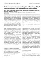
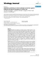
IEC publication 60479-1 updated in 2005 defines four zones of current-magnitude/
time-duration, in each of which the pathophysiological effects are described (see Fig
F1). Any person coming into contact with live metal risks an electric shock.
Curve C1 shows that when a current greater than 30 mA passes through a human
being from one hand to feet, the person concerned is likely to be killed, unless the
current is interrupted in a relatively short time.
The point 500 ms/100 mA close to the curve C1 corresponds to a probability of heart
fibrillation of the order of 0.14%.
The protection of persons against electric shock in LV installations must be provided
in conformity with appropriate national standards and statutory regulations, codes of
practice, official guides and circulars, etc. Relevant IEC standards include:
IEC 60364
series, IEC 60479 series, IEC 60755, IEC 61008 series, IEC 61009 series
and IEC
60947-2.
Fig. F1 : Zones time/current of effects of AC current on human body when passing from left hand to feet
Body current
I
s
(mA)
10
20
50
100
200
500
1,000
5,000
10,000
2,000
C
1
C
2
C
3
Duration of current
flow
I
(ms)
A B
AC-2 AC-3 AC-4
0.1 0.2 0.5 1 2 5 10 20 50 100 200 500
1,000
2,000
5,000
10,000
AC-1
AC-4.1
AC-4.2
AC-4.3
AC-1 zone: Imperceptible
AC-2 zone: Perceptible
AC-3 zone : Reversible effects: muscular contraction
AC-4 zone: Possibility of irreversible effects
AC-4-1 zone: Up to 5%probability of heart fibrillation
AC-4-2 zone: Up to 50% probability of heart fibrillation
AC-4-3 zone: More than 50% probability of heart fibrillation
When a current exceeding 30 mA passes
through a part of a human body, the person
concerned is in serious danger if the current is
not interrupted in a very short time.
The protection of persons against electric
shock in LV installations must be provided in
conformity with appropriate national standards
statutory regulations, codes of practice, official
guides and circulars etc.
Relevant IEC standards include: IEC 60364,
IEC 60479 series, IEC 61008, IEC 61009 and
IEC 60947-2.
A curve: Threshold of perception of current
B curve: Threshold of muscular reactions
C
1
curve: Threshold of 0% probability of ventricular
fibrillation
C
2
curve: Threshold of 5% probability of ventricular
fibrillation
C
3
curve: Threshold of 50% probability of ventricular
fibrillation
EIG_chap_F-2010.indb 2 04/12/2009 12:02:42
F3
Schneider Electric - Electrical installation guide 2010
© Schneider Electric - all rights reserved
1.2 Protection against electric shock
The fundamental rule of protection against electric shock is provided by the
document IEC 61140 which covers both electrical installations and electrical
equipment.
Hazardous-live-parts shall not be accessible and accessible conductive parts shall
not be hazardous.
This requirement needs to apply under:
b Normal conditions, and
b Under a single fault condition
Various measures are adopted to protect against this hazard, and include:
b Automatic disconnection of the power supply to the connected electrical equipment
b Special arrangements such as:
v The use of class II insulation materials, or an equivalent level of insulation
v Non-conducting location, out of arm’s reach or interposition of barriers
v Equipotential bonding
v Electrical separation by means of isolating transformers
1.3 Direct and indirect contact
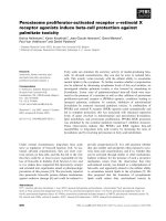
Direct contact
A direct contact refers to a person coming into contact with a conductor which is live
in normal circumstances (see Fig. F2).
IEC 61140 standard has renamed “protection against direct contact” with the term
“basic protection”. The former name is at least kept for information.
Indirect contact
An indirect contact refers to a person coming into contact with an exposed-
conductive-part which is not normally alive, but has become alive accidentally (due
to insulation failure or some other cause).
The fault current raise the exposed-conductive-part to a voltage liable to be
hazardous which could be at the origin of a touch current through a person coming
into contact with this exposed-conductive-part (see Fig. F3).
IEC 61140 standard has renamed “protection against indirect contact” with the term
“fault protection”. The former name is at least kept for information.
Two measures of protection against direct
contact hazards are often required, since, in
practice, the first measure may not be infallible
Standards and regulations distinguish two kinds
of dangerous contact,
b
Direct contact
b
Indirect contact
and corresponding protective measures
Busbars
1 2 3 N
I
s: Touch current
I
s
Insulation
failure
1 2 3 PE
I
d
I
d: Insulation fault current
I
s
Fig. F2 : Direct contact Fig F3 : Indirect contact
1 General
EIG_chap_F-2010.indb 3 04/12/2009 12:02:42
Schneider Electric - Electrical installation guide 2010
F - Protection against electric shock
F4
© Schneider Electric - all rights reserved
2 Protection against direct contact
Two complementary measures are commonly used as protection against the
dangers of direct contact:
b The physical prevention of contact with live parts by barriers, insulation,
inaccessibility, etc.
b Additional protection in the event that a direct contact occurs, despite or due to
failure of the above measures. This protection is based on residual-current operating
device with a high sensitivity (
IΔ
n y 30 mA) and a low operating time. These devices
are highly effective in the majority of case of direct contact.
2.1 Measures of protection against direct contact
Protection by the insulation of live parts
This protection consists of an insulation which complies with the relevant standards
(see Fig. F4). Paints, lacquers and varnishes do not provide an adequate protection.
IEC and national standards frequently
distinguish two protections:
b
Complete (insulation, enclosures)
b
Partial or particular
Fig. F4 : Inherent protection against direct contact by insulation of a 3-phase cable with outer
sheath
Fig. F5 : Example of isolation by envelope
Protection by means of barriers or enclosures
This measure is in widespread use, since many components and materials are
installed in cabinets, assemblies, control panels and distribution boards (see Fig. F5)
.
To be considered as providing effective protection against direct contact hazards,
these equipment must possess a degree of protection equal to at least IP 2X or
IP XXB (see chapter E sub-clause 3.4).
Moreover, an opening in an enclosure (door, front panel, drawer, etc.) must only be
removable, open or withdrawn:
b By means of a key or tool provided for this purpose, or
b After complete isolation of the live parts in the enclosure, or
b With the automatic interposition of another screen removable only with a key or
a tool. The metal enclosure and all metal removable screen must be bonded to the
protective earthing conductor of the installation.
Partial measures of protection
b Protection by means of obstacles, or by placing out of arm’s reach
This protection is reserved only to locations to which skilled or instructed
persons only have access. The erection of this protective measure is detailed in
IEC 60364-4-41.
Particular measures of protection
b Protection by use of extra-low voltage SELV (Safety Extra-Low Voltage) or by
limitation of the energy of discharge.
These measures are used only in low-power circuits, and in particular circumstances,
as described in section 3.5.
EIG_chap_F-2010.indb 4 04/12/2009 12:02:42
Schneider Electric - Electrical installation guide 2010
F5
© Schneider Electric - all rights reserved
2.2 Additional measure of protection against direct
contact
All the preceding protective measures are preventive, but experience has shown
that for various reasons they cannot be regarded as being infallible. Among these
reasons may be cited:
b Lack of proper maintenance
b Imprudence, carelessness
b Normal (or abnormal) wear and tear of insulation; for instance flexure and abrasion
of connecting leads
b Accidental contact
b Immersion in water, etc. A situation in which insulation is no longer effective
In order to protect users in such circumstances, highly sensitive fast tripping
devices, based on the detection of residual currents to earth (which may or may
not be through a human being or animal) are used to disconnect the power
supply automatically, and with sufficient rapidity to prevent injury to, or death by
electrocution, of a normally healthy human being
(see Fig. F6)
.
These devices operate on the principle of differential current measurement, in which
any difference between the current entering a circuit and that leaving it (on a system
supplied from an earthed source) be flowing to earth, either through faulty insulation
or through contact of an earthed part, such as a person, with a live conductor.
Standardised residual-current devices, referred to as RCDs, sufficiently sensitive for
protection against direct contact are rated at 30 mA of differential current.
According to IEC 60364-4-41, additional protection by means of high sensitivity
RCDs (
I
∆n y 30 mA) must be provided for circuits supplying socket-outlets with a
rated current y 20 A in all locations, and for circuits supplying mobile equipment with
a rated current y 32 A for use outdoors.
This additional protection is required in certain countries for circuits supplying socket-
outlets rated up to 32 A, and even higher if the location is wet and/or temporary
(such as work sites for instance).
It is also recommended to limit the number of socket-outlets protected by a RCD
(e.g. 10 socket-outlets for one RCD).
Chapter P section 3 itemises various common locations in which RCDs of
high sensitivity are obligatory (in some countries), but in any case, are highly
recommended as an effective protection against both direct and indirect contact
hazards.
An additional measure of protection against
the hazards of direct contact is provided by the
use of residual current operating device, which
operate at 30 mA or less, and are referred to as
RCDs of high sensitivity
Fig. F6 : High sensitivity RCD
2 Protection against direct contact
EIG_chap_F-2010.indb 5 04/12/2009 12:02:42
Schneider Electric - Electrical installation guide 2010
F - Protection against electric shock
F6
© Schneider Electric - all rights reserved
3 Protection against indirect
contact
Exposed-conductive-parts used in the manufacturing process of an electrical
equipment is separated from the live parts of the equipment by the “basic insulation”.
Failure of the basic insulation will result in the exposed-conductive-parts being alive.
Touching a normally dead part of an electrical equipment which has become live due
to the failure of its insulation, is referred to as an indirect contact.
3.1 Measures of protection: two levels
Two levels of protective measures exist:
b 1
st
level: The earthing of all exposed-conductive-parts of electrical equipment in the
installation and the constitution of an equipotential bonding network (see chapter G
section 6).
b 2
sd
level: Automatic disconnection of the supply of the section of the installation
concerned, in such a way that the touch-voltage/time safety requirements are
respected for any level of touch voltage Uc
(1)
(see Fig. F7).
(1) Touch voltage Uc is the voltage existing (as the result of
insulation failure) between an exposed-conductive-part and
any conductive element within reach which is at a different
(generally earth) potential.
Protection against indirect contact hazards
can be achieved by automatic disconnection of
the supply if the exposed-conductive-parts of
equipment are properly earthed
Uc
Earth
connection
Fig. F7 : Illustration of the dangerous touch voltage Uc
Fig. F8 : Maximum safe duration of the assumed values of AC touch voltage (in seconds)
Uo (V) 50 < Uo y 120 120 < Uo y 230 230 < Uo y 400 Uo > 400
System TN or IT 0.8 0.4 0.2 0.1
TT 0.3 0.2 0.07 0.04
The greater the value of Uc, the greater the rapidity of supply disconnection required
to provide protection (see Fig. F8). The highest value of Uc that can be tolerated
indefinitely without danger to human beings is 50 V CA.
Reminder of the theoretical disconnecting-time limits
EIG_chap_F-2010.indb 6 04/12/2009 12:02:42
Schneider Electric - Electrical installation guide 2010
F7
© Schneider Electric - all rights reserved
3.2 Automatic disconnection for TT system
Principle
In this system all exposed-conductive-parts and extraneous-conductive-parts of
the installation must be connected to a common earth electrode. The neutral point
of the supply system is normally earthed at a pint outside the influence area of the
installation earth electrode, but need not be so. The impedance of the earth-fault loop
therefore consists mainly in the two earth electrodes (i.e. the source and installation
electrodes) in series, so that the magnitude of the earth fault current is generally
too small to operate overcurrent relay or fuses, and the use of a residual current
operated device is essential.
This principle of protection is also valid if one common earth electrode only is used,
notably in the case of a consumer-type substation within the installation area, where
space limitation may impose the adoption of a TN system earthing, but where all
other conditions required by the TN system cannot be fulfilled.
Protection by automatic disconnection of the supply used in TT system is by RCD of
sensitivity:
I
6
n
R
i
50
A
where R
installation earth electrode
where
R
A
is the resistance of the earth electrode for the installation
I
Δ
n
is the rated residual operating current of the RCD
For temporary supplies (to work sites, …) and agricultural and horticultural premises,
the value of 50 V is replaced by 25 V.
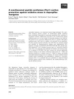
Example (see Fig. F9)
b The resistance of the earth electrode of substation neutral R
n
is 10
Ω
.
b The resistance of the earth electrode of the installation R
A
is 20
Ω
.
b The earth-fault loop current
I
d
= 7.7 A.
b The fault voltage U
f
=
I
d
x R
A
= 154 V and therefore dangerous, but
I
Δ
n
= 50/20 = 2.5 A so that a standard 300 mA RCD will operate in about 30 ms
without intentional time delay and will clear the fault where a fault voltage exceeding
appears on an exposed-conductive-part.
Fig. F10 : Maximum disconnecting time for AC final circuits not exceeding 32 A
1
2
3
N
PE
R
n
= 10
Ω
Substation
earth
electrode
Installation
earth
electrode
R
A
= 20
Ω
U
f
Fig. F9 : Automatic disconnection of supply for TT system
Automatic disconnection for TT system is
achieved by RCD having a sensitivity of
I
6
n
R
i
50
A
where R
installation earth electrode
where R
A
is the resistance of the
installation earth electrode
3 Protection against indirect
contact
(1) Uo is the nominal phase to earth voltage
Uo
(1)
(V) T (s)
50 < Uo y 120 0.3
120 < Uo y 230 0.2
230 < Uo y 400 0.07
Uo > 400 0.04
Specified maximum disconnection time
The tripping times of RCDs are generally lower than those required in the majority
of national standards; this feature facilitates their use and allows the adoption of an
effective discriminative protection.
The IEC 60364-4-41 specifies the maximum operating time of protective devices
used in TT system for the protection against indirect contact:
b For all final circuits with a rated current not exceeding 32 A, the maximum
disconnecting time will not exceed the values indicated in Figure F10
b For all other circuits, the maximum disconnecting time is fixed to 1s. This limit
enables discrimination between RCDs when installed on distribution circuits.
RCD is a general term for all devices operating on the residual-current principle.
RCCB (Residual Current Circuit-Breaker) as defined in IEC 61008 series is a specific
class of RCD.
Type G (general) and type S (Selective) of IEC 61008 have a tripping time/current
characteristics as shown in Figure F11 next page. These characteristics allow a certain
degree of selective tripping between the several combination of ratings and types, as
shown later in sub-clause 4.3. Industrial type RCD according to IEC 60947-2 provide
more possibilities of discrimination due to their flexibility of time-delaying.
EIG_chap_F-2010.indb 7 04/12/2009 12:02:43
Schneider Electric - Electrical installation guide 2010
F - Protection against electric shock
F8
© Schneider Electric - all rights reserved
3.3 Automatic disconnection for TN systems
Principle
In this system all exposed and extraneous-conductive-parts of the installation are
connected directly to the earthed point of the power supply by protective conductors.
As noted in Chapter E Sub-clause 1.2, the way in which this direct connection is
carried out depends on whether the TN-C, TN-S, or TN-C-S method of implementing
the TN principle is used. In figure F12 the method TN-C is shown, in which the
neutral conductor acts as both the Protective-Earth and Neutral (PEN) conductor. In
all TN systems, any insulation fault to earth results in a phase to neutral short-circuit.
High fault current levels allow to use overcurrent protection but can give rise to touch
voltages exceeding 50% of the phase to neutral voltage at the fault position during
the short disconnection time.
In practice for utility distribution network, earth electrodes are normally installed at
regular intervals along the protective conductor (PE or PEN) of the network, while
the consumer is often required to install an earth electrode at the service entrance.
On large installations additional earth electrodes dispersed around the premises are
often provided, in order to reduce the touch voltage as much as possible. In high-rise
apartment blocks, all extraneous conductive parts are connected to the protective
conductor at each level. In order to ensure adequate protection, the earth-fault
current
I I
d or 0.8
Uo
Zc
=
Uo
Zs
u
must be higher or equal to
I
a, where:
b Uo = nominal phase to neutral voltage
b
I
d = the fault current
b
I
a = current equal to the value required to operate the protective device in the time
specified
b Zs = earth-fault current loop impedance, equal to the sum of the impedances of the
source, the live phase conductors to the fault position, the protective conductors from
the fault position back to the source
b Zc = the faulty-circuit loop impedance (see “conventional method” Sub-clause 6.2)
Note: The path through earth electrodes back to the source will have (generally)
much higher impedance values than those listed above, and need not be considered.
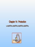
Example (see Fig. F12)
The fault voltage
The fault voltage
Uf = =
230
2
115 V
and is hazardous;
and is hazardous;
The fault loop impedance Zs=Z
ab
+ Z
bc
+ Z
de
+ Z
en
+ Z
na
.
If Z
bc
and Z
de
are predominant, then:
Zs
L
S
= =2 64 3
l
. m
1
, so that
, so that
“conventional method” and in this example will give an estimated fault current of
=
(
I
d =
230
64.3 x10
-3
3,576 A
(
≈
22
I
n based on a NSX160 circuit-breaker).
The “instantaneous” magnetic trip unit adjustment of the circuit-breaker is many time
less than this short-circuit value, so that positive operation in the shortest possible
time is assured.
Note: Some authorities base such calculations on the assumption that a voltage
drop of 20% occurs in the part of the impedance loop BANE.
This method, which is recommended, is explained in chapter F sub-clause 6.2
“conventional method” and in this example will give an estimated fault current of
“conventional method” and in this example will give an estimated fault current of
230 x 0.8 x 10
64.3
2,816 A
3
=
(
(
≈
18
I
n).
Fig. F12 : Automatic disconnection in TN system
1
2
3
PEN
NSX160
A
F
N
E
D C
B
U
f
35 mm
2
50 m
35 mm
2
Fig. F11 : Maximum operating time of RCD’s (in seconds)
x I
Δ
n
1 2 5 > 5
Domestic Instantaneous 0.3 0.15 0.04 0.04
Type S 0.5 0.2 0.15 0.15
Industrial Instantaneous 0.3 0.15 0.04 0.04
Time-delay (0.06) 0.5 0.2 0.15 0.15
Time-delay (other) According to manufacturer
The automatic disconnection for TN system is
achieved by overcurrent protective devices or
RCD’s
EIG_chap_F-2010.indb 8 04/12/2009 12:02:43
Schneider Electric - Electrical installation guide 2010
F9
© Schneider Electric - all rights reserved
Specified maximum disconnection time
The IEC 60364-4-41 specifies the maximum operating time of protective devices
used in TN system for the protection against indirect contact:
b For all final circuits with a rated current not exceeding 32 A, the maximum
disconnecting time will not exceed the values indicated in Figure F13
b For all other circuits, the maximum disconnecting time is fixed to 5s. This limit
enables discrimination between protective devices installed on distribution circuits
Note: The use of RCDs may be necessary on TN-earthed systems. Use of RCDs on
TN-C-S systems means that the protective conductor and the neutral conductor must
(evidently) be separated upstream of the RCD. This separation is commonly made at
the service entrance.
Fig. F13 : Maximum disconnecting time for AC final circuits not exceeding 32 A
1
1: Short-time delayed trip
2: Instantaneous trip
I
m Uo/Zs
I
2
t
I
a Uo/Zs
t
tc = 0.4 s
I
If the protection is to be provided by a circuit-
breaker, it is sufficient to verify that the fault
current will always exceed the current-setting
level of the instantaneous or short-time delay
tripping unit (
I
m)
I
a can be determined from the fuse
performance curve. In any case, protection
cannot be achieved if the loop impedance Zs
or Zc exceeds a certain value
Fig. F14 : Disconnection by circuit-breaker for a TN system Fig. F15 : Disconnection by fuses for a TN system
3 Protection against indirect
contact
(1) Uo is the nominal phase to earth voltage
Uo
(1)
(V) T (s)
50 < Uo y 120 0.8
120 < Uo y 230 0.4
230 < Uo y 400 0.2
Uo > 400 0.1
Protection by means of circuit-breaker
(see Fig. F14)
The instantaneous trip unit of a circuit-breaker will eliminate a short-circuit to earth in
less than 0.1 second.
In consequence, automatic disconnection within the maximum allowable time will
always be assured, since all types of trip unit, magnetic or electronic, instantaneous
or slightly retarded, are suitable:
I
a =
I
m. The maximum tolerance authorised
by the relevant standard, however, must always be taken into consideration. It is
sufficient therefore that the fault current
therefore that the fault current
Uo
Zs
or 0.8
Uo
Zc
determined by calculation (or estimated
on site) be greater than the instantaneous trip-setting current, or than the very short-
determined by calculation
(or estimated on site) be greater than the instantaneous trip-setting current, or than
the very short-time tripping threshold level, to be sure of tripping within the permitted
time limit.
Protection by means of fuses
(see Fig. F15)
The value of current which assures the correct operation of a fuse can be
ascertained from a current/time performance graph for the fuse concerned.
The fault current
therefore that the fault current
Uo
Zs
or 0.8
Uo
Zc
determined by calculation (or estimated
on site) be greater than the instantaneous trip-setting current, or than the very short-
as determined above, must largely exceed that
necessary to ensure positive operation of the fuse. The condition to observe
therefore is that
necessary to ensure positive operation of the fuse. The condition to observe
therefore is that
I
a <
Uo
Zs
or 0.8
Uo
Zc
as indicated in Figure F15.
as indicated in Figure F15.
EIG_chap_F-2010.indb 9 04/12/2009 12:02:44
Schneider Electric - Electrical installation guide 2010
F - Protection against electric shock
F10
© Schneider Electric - all rights reserved
Example: The nominal phase to neutral voltage of the network is 230 V and
the maximum disconnection time given by the graph in Figure F15 is 0.4 s.
The corresponding value of Ia can be read from the graph. Using the voltage (230 V)
and the current
I
a, the complete loop impedance or the circuit loop impedance can
be calculated from
I
a, the complete loop impedance or the circuit loop impedance can
be calculated from
Zs
a a
= =
230
I I
or Zc 0.8
230
. This impedance value must never be
. This impedance value must never be
exceeded and should preferably be substantially less to ensure satisfactory fuse
operation.
Protection by means of Residual Current Devices for
TN-S circuits
Residual Current Devices must be used where:
b The loop impedance cannot be determined precisely (lengths difficult to estimate,
presence of metallic material close to the wiring)
b The fault current is so low that the disconnecting time cannot be met by using
overcurrent protective devices
The rated tripping current of RCDs being in the order of a few amps, it is well below
the fault current level. RCDs are consequently well adapted to this situation.
In practice, they are often installed in the LV sub distribution and in many countries,
the automatic disconnection of final circuits shall be achieved by Residual Current
Devices.
3.4 Automatic disconnection on a second fault in an
IT system
In this type of system:
b The installation is isolated from earth, or the neutral point of its power-supply
source is connected to earth through a high impedance
b All exposed and extraneous-conductive-parts are earthed via an installation earth
electrode.
First fault situation
On the occurrence of a true fault to earth, referred to as a “first fault”, the fault current
is very low, such that the rule
I
d x R
A
y 50 V (see F3.2) is fulfilled and no dangerous
fault voltages can occur.
In practice the current
I
d is low, a condition that is neither dangerous to personnel,
nor harmful to the installation.
However, in this system:
b A permanent monitoring of the insulation to earth must be provided, coupled with
an alarm signal (audio and/or flashing lights, etc.) operating in the event of a first
earth fault (see Fig. F16)
b The rapid location and repair of a first fault is imperative if the full benefits of the
IT system are to be realised. Continuity of service is the great advantage afforded by
the system.
For a network formed from 1 km of new conductors, the leakage (capacitive)
impedance to earth Zf is of the order of 3,500
Ω
per phase. In normal operation, the
capacitive current
(1)
to earth is therefore:
Uo
Zf
= =
230
3,500
66 mA
per phase.
per phase.
During a phase to earth fault, as indicated in Figure F17 opposite page, the current
passing through the electrode resistance RnA is the vector sum of the capacitive
currents in the two healthy phases. The voltages of the healthy phases have
(because of the fault) increased to 3 the normal phase voltage, so that the capacitive
currents increase by the same amount. These currents are displaced, one from the
other by 60°, so that when added vectorially, this amounts to 3 x 66 mA = 198 mA, in
the present example.
The fault voltage Uf is therefore equal to 198 x 5 x 10
-3
= 0.99 V, which is obviously
harmless.
The current through the short-circuit to earth is given by the vector sum of the
neutral-resistor current
I
d1 (=153 mA) and the capacitive current
I
d2 (198 mA).
Since the exposed-conductive-parts of the installation are connected directly to
earth, the neutral impedance Zct plays practically no part in the production of touch
voltages to earth.
In IT system the first fault to earth should not
cause any disconnection
(1) Resistive leakage current to earth through the insulation is
assumed to be negligibly small in the example.
Fig. F16 : Phases to earth insulation monitoring device
obligatory in IT system
EIG_chap_F-2010.indb 10 04/12/2009 12:02:44
Schneider Electric - Electrical installation guide 2010
F11
© Schneider Electric - all rights reserved
Second fault situation
On the appearance of a second fault, on a different phase, or on a neutral conductor,
a rapid disconnection becomes imperative. Fault clearance is carried out differently in
each of the following cases:
1
st
case
It concerns an installation in which all exposed conductive parts are bonded to a
common PE conductor, as shown in Figure F18.
In this case no earth electrodes are included in the fault current path, so that a high
level of fault current is assured, and conventional overcurrent protective devices are
used, i.e. circuit-breakers and fuses.
The first fault could occur at the end of a circuit in a remote part of the installation,
while the second fault could feasibly be located at the opposite end of the installation.
For this reason, it is conventional to double the loop impedance of a circuit, when
calculating the anticipated fault setting level for its overcurrent protective device(s).
Where the system includes a neutral conductor in addition to the 3 phase
conductors, the lowest short-circuit fault currents will occur if one of the (two) faults is
from the neutral conductor to earth (all four conductors are insulated from earth in an
IT scheme). In four-wire IT installations, therefore, the phase-to-neutral voltage must
be used to calculate short-circuit protective levels i.e.
be used to calculate short-circuit protective levels i.e.
0.8
Uo
2 Zc
au
I
(1)
(1)
where
Uo = phase to neutral voltage
Zc = impedance of the circuit fault-current loop (see F3.3)
Ia = current level for trip setting
If no neutral conductor is distributed, then the voltage to use for the fault-current
calculation is the phase-to-phase value, i.e.
calculation is the phase-to-phase value, i.e.
0.8
3 Uo
2 Zc
au
I
(1)
(1)
b Maximum tripping times
Disconnecting times for IT system depends on how the different installation and
substation earth electrodes are interconnected.
For final circuits supplying electrical equipment with a rated current not exceeding
32 A and having their exposed-conductive-parts bonded with the substation earth
electrode, the maximum tripping time is given in table F8. For the other circuits
within the same group of interconnected exposed-conductive-parts, the maximum
disconnecting time is 5 s. This is due to the fact that any double fault situation within
this group will result in a short-circuit current as in TN system.
For final circuits supplying electrical equipment with a rated current not exceeding
32 A and having their exposed-conductive-parts connected to an independent earth
electrode electrically separated from the substation earth electrode, the maximum
tripping time is given in Figure F13. For the other circuits within the same group of
non interconnected exposed-conductive-parts, the maximum disconnecting time is
1s. This is due to the fact that any double fault situation resulting from one insulation
fault within this group and another insulation fault from another group will generate a
fault current limited by the different earth electrode resistances as in TT system.
1
I
d2
I
d1
I
d1 +
I
d2
2
3
N
PE
R
nA
= 5
Ω
Z
ct
= 1,500
Ω
Zf
B
U
f
Ω
The simultaneous existence of two earth faults
(if not both on the same phase) is dangerous,
and rapid clearance by fuses or automatic
circuit-breaker tripping depends on the type of
earth-bonding scheme, and whether separate
earthing electrodes are used or not, in the
installation concerned
(1) Based on the “conventional method” noted in the first
example of Sub-clause 3.3.
3 Protection against indirect
contact
Fig. F17 : Fault current path for a first fault in IT system
EIG_chap_F-2010.indb 11 04/12/2009 12:02:44
Schneider Electric - Electrical installation guide 2010
F - Protection against electric shock
F12
© Schneider Electric - all rights reserved
b Protection by circuit-breaker
In the case shown in Figure F18, the adjustments of instantaneous and short-time
delay overcurrent trip unit must be decided. The times recommended here above can
be readily complied with. The short-circuit protection provided by the NSX160 circuit-
breaker is suitable to clear a phase to phase short-circuit occurring at the load ends
of the circuits concerned.
Reminder: In an IT system, the two circuits involved in a phase to phase short-circuit
are assumed to be of equal length, with the same cross sectional area conductors,
the PE conductors being the same cross sectional area as the phase conductors. In
such a case, the impedance of the circuit loop when using the “conventional method”
(sub clause 6.2) will be twice that calculated for one of the circuits in the TN case,
shown in Chapter F sub clause 3.3.
The resistance of circuit loop FGHJ = 2R
JH
=
So that the resistance of circuit 1 loop
FGHJ RJH
L
a
= =2 2 in m
l 1
where:
where:
ρ
= resistance of copper rod 1 meter long of cross sectional area 1 mm
2
, in m
Ω
L = length of the circuit in meters
a = cross sectional area of the conductor in mm
2
FGHJ = 2 x 22.5 x 50/35 = 64.3 m
Ω
and the loop resistance B, C, D, E, F, G, H, J will be 2 x 64.3 = 129 m
Ω
.
The fault current will therefore be 0.8 x 3 x 230 x 10
3
/129 = 2,470 A.
b Protection by fuses
The current
I
a
for which fuse operation must be assured in a time specified according
to here above can be found from fuse operating curves, as described in figure F15.
The current indicated should be significantly lower than the fault currents calculated
for the circuit concerned.
b Protection by Residual current circuit-breakers (RCCBs)
For low values of short-circuit current, RCCBs are necessary. Protection against
indirect contact hazards can be achieved then by using one RCCB for each circuit.
2
nd
case
b
It concerns exposed conductive parts which are earthed either individually (each part
having its own earth electrode) or in separate groups (one electrode for each group).
If all exposed conductive parts are not bonded to a common electrode system, then
it is possible for the second earth fault to occur in a different group or in a separately
earthed individual apparatus. Additional protection to that described above for
case 1, is required, and consists of a RCD placed at the circuit-breaker controlling
each group and each individually-earthed apparatus.
Fig. F18 : Circuit-breaker tripping on double fault situation when exposed-conductive-parts are
connected to a common protective conductor
1
I
d
2
3
N
PE
NSX160
160 A
50 m
35 mm
2
50 m
35 mm
2
R
A
E
DHG
BA
K
F
J
C
EIG_chap_F-2010.indb 12 04/12/2009 12:02:44
Schneider Electric - Electrical installation guide 2010
F13
© Schneider Electric - all rights reserved
Fig. F19 : Correspondence between the earth leakage capacitance and the first fault current
Group
earth
Case 1
PIM
Ω
N
R
A
R
n
RCD
Group
earth 2
Group
earth 1
Case 2
PIM
Ω
N
R
A1
R
n
R
A2
RCD
RCD RCD
Fig. F20 : Application of RCDs when exposed-conductive-parts are earthed individually or by group on IT system
Leakage capacitance First fault current
(µF) (A)
1 0.07
5 0.36
30 2.17
Note: 1 µF is the 1 km typical leakage capacitance for
4-conductor cable.
The reason for this requirement is that the separate-group electrodes are “bonded”
through the earth so that the phase to phase short-circuit current will generally be
limited when passing through the earth bond by the electrode contact resistances
with the earth, thereby making protection by overcurrent devices unreliable. The
more sensitive RCDs are therefore necessary, but the operating current of the RCDs
must evidently exceed that which occurs for a first fault (see Fig. F19).
3 Protection against indirect
contact
Extra-low voltage is used where the risks
are great: swimming pools, wandering-lead
hand lamps, and other portable appliances for
outdoor use, etc.
For a second fault occurring within a group having a common earth-electrode
system, the overcurrent protection operates, as described above for case 1.
Note 1
: See also Chapter G Sub-clause 7.2, protection of the neutral conductor.
Note 2: In 3-phase 4-wire installations, protection against overcurrent in the neutral
conductor is sometimes more conveniently achieved by using a ring-type current
transformer over the single-core neutral conductor (see Fig. F20).
3.5 Measures of protection against direct or indirect
contact without automatic disconnection of supply
The use of SELV (Safety Extra-Low Voltage)
Safety by extra low voltage SELV is used in situations where the operation of electrical
equipment presents a serious hazard (swimming pools, amusement parks, etc.).
This measure depends on supplying power at extra-low voltage from the secondary
windings of isolating transformers especially designed according to national or to
international (IEC 60742) standard. The impulse withstand level of insulation between
the primary and secondary windings is very high, and/or an earthed metal screen
is sometimes incorporated between the windings. The secondary voltage never
exceeds 50 V rms.
Three conditions of exploitation must be respected in order to provide satisfactory
protection against indirect contact:
b No live conductor at SELV must be connected to earth
b Exposed-conductive-parts of SELV supplied equipment must not be connected to
earth, to other exposed conductive parts, or to extraneous-conductive-parts
b All live parts of SELV circuits and of other circuits of higher voltage must be
separated by a distance at least equal to that between the primary and secondary
windings of a safety isolating transformer.
EIG_chap_F-2010.indb 13 04/12/2009 12:02:45
Schneider Electric - Electrical installation guide 2010
F - Protection against electric shock
F14
© Schneider Electric - all rights reserved
These measures require that:
b
SELV circuits must use conduits exclusively provided for them, unless cables which
are insulated for the highest voltage of the other circuits are used for the SELV circuits
b Socket outlets for the SELV system must not have an earth-pin contact. The
SELV circuit plugs and sockets must be special, so that inadvertent connection to a
different voltage level is not possible.
Note: In normal conditions, when the SELV voltage is less than 25 V, there is no
need to provide protection against direct contact hazards. Particular requirements
are indicated in Chapter P, Clause 3: “special locations”.
The use of PELV (Protection by Extra Low Voltage)
(see Fig. F21)
This system is for general use where low voltage is required, or preferred for safety
reasons, other than in the high-risk locations noted above. The conception is similar
to that of the SELV system, but the secondary circuit is earthed at one point.
IEC 60364-4-41 defines precisely the significance of the reference PELV. Protection
against direct contact hazards is generally necessary, except when the equipment
is in the zone of equipotential bonding, and the nominal voltage does not exceed
25 V rms, and the equipment is used in normally dry locations only, and large-area
contact with the human body is not expected. In all other cases, 6 V rms is the
maximum permitted voltage, where no direct contact protection is provided.
Fig. F21 : Low-voltage supplies from a safety isolating transformer
Fig. F22 : Safety supply from a class II separation transformer
230 V / 24 V
FELV system (Functional Extra-Low Voltage)
Where, for functional reasons, a voltage of 50 V or less is used, but not all of the
requirements relating to SELV or PELV are fulfilled, appropriate measures described
in IEC 60364-4-41 must be taken to ensure protection against both direct and
indirect contact hazards, according to the location and use of these circuits.
Note: Such conditions may, for example, be encountered when the circuit contains
equipment (such as transformers, relays, remote-control switches, contactors)
insufficiently insulated with respect to circuits at higher voltages.
The electrical separation of circuits
(see Fig. F22)
The principle of the electrical separation of circuits (generally single-phase circuits)
for safety purposes is based on the following rationale.
The two conductors from the unearthed single-phase secondary winding of a
separation transformer are insulated from earth.
If a direct contact is made with one conductor, a very small current only will flow into
the person making contact, through the earth and back to the other conductor, via
the inherent capacitance of that conductor with respect to earth. Since the conductor
capacitance to earth is very small, the current is generally below the level of perception.
As the length of circuit cable increases, the direct contact current will progressively
increase to a point where a dangerous electric shock will be experienced.
Even if a short length of cable precludes any danger from capacitive current, a low
value of insulation resistance with respect to earth can result in danger, since the
current path is then via the person making contact, through the earth and back to the
other conductor through the low conductor-to-earth insulation resistance.
For these reasons, relatively short lengths of well insulated cables are essential in
separation systems.
Transformers are specially designed for this duty, with a high degree of insulation
between primary and secondary windings, or with equivalent protection, such as an
earthed metal screen between the windings. Construction of the transformer is to
class II insulation standards.
The electrical separation of circuits is suitable
for relatively short cable lengths and high levels
of insulation resistance. It is preferably used for
an individual appliance
230 V/230 V
EIG_chap_F-2010.indb 14 04/12/2009 12:02:45
Schneider Electric - Electrical installation guide 2010
F15
© Schneider Electric - all rights reserved
3 Protection against indirect
contact
(1) It is recommended in IEC 364-4-41 that the product of the
nominal voltage of the circuit in volts and length in metres of
the wiring system should not exceed 100,000, and that the
length of the wiring system should not exceed 500 m.
As indicated before, successful exploitation of the principle requires that:
b No conductor or exposed conductive part of the secondary circuit must be
connected to earth,
b
The length of secondary cabling must be limited to avoid large capacitance values
(1)
,
b
A high insulation-resistance value must be maintained for the cabling and appliances.
These conditions generally limit the application of this safety measure to an
individual appliance.
In the case where several appliances are supplied from a separation transformer, it is
necessary to observe the following requirements:
b The exposed conductive parts of all appliances must be connected together by an
insulated protective conductor, but not connected to earth,
b The socket outlets must be provided with an earth-pin connection. The earth-pin
connection is used in this case only to ensure the interconnection (bonding) of all
exposed conductive parts.
In the case of a second fault, overcurrent protection must provide automatic
disconnection in the same conditions as those required for an IT system of power
system earthing.
Class II equipment
These appliances are also referred to as having “double insulation” since in class
II appliances a supplementary insulation is added to the basic insulation (see
Fig. F23
).
No conductive parts of a class II appliance must be connected to a protective conductor:
b Most portable or semi-fixed equipment, certain lamps, and some types of
transformer are designed to have double insulation. It is important to take particular
care in the exploitation of class II equipment and to verify regularly and often that the
class II standard is maintained (no broken outer envelope, etc.). Electronic devices,
radio and television sets have safety levels equivalent to class II, but are not formally
class II appliances
b Supplementary insulation in an electrical installation: IEC 60364-4-41(Sub-clause
413-2) and some national standards such as NF C 15-100 (France) describe in
more detail the necessary measures to achieve the supplementary insulation during
installation work.
Class II equipment symbol:
Fig. F23 : Principle of class II insulation level
Active part
Basic insulation
Supplementary insulation
A simple example is that of drawing a cable into a PVC conduit. Methods are also
described for distribution switchboards.
b For distribution switchboards and similar equipment, IEC 60439-1 describes a set
of requirements, for what is referred to as “total insulation”, equivalent to class II
b
Some cables are recognised as being equivalent to class II by many national standards
Out-of-arm’s reach or interposition of obstacles
By these means, the probability of touching a live exposed-conductive-part, while at
the same time touching an extraneous-conductive-part at earth potential, is extremely
low (see Fig. F24 next page). In practice, this measure can only be applied in a dry
location, and is implemented according to the following conditions:
b The floor and the wall of the chamber must be non-conducting, i.e. the resistance
to earth at any point must be:
v > 50 k
Ω
(installation voltage y 500 V)
v > 100 k
Ω
(500 V < installation voltage y 1000 V)
Resistance is measured by means of “MEGGER” type instruments (hand-operated
generator or battery-operated electronic model) between an electrode placed on the
floor or against the wall, and earth (i.e. the nearest protective earth conductor). The
electrode contact area pressure must be evidently be the same for all tests.
Different instruments suppliers provide electrodes specific to their own product, so
that care should be taken to ensure that the electrodes used are those supplied with
the instrument.
In principle, safety by placing simultaneously-
accessible conductive parts out-of-reach, or by
interposing obstacles, requires also a non-
conducting floor, and so is not an easily applied
principle
EIG_chap_F-2010.indb 15 04/12/2009 12:02:45
Schneider Electric - Electrical installation guide 2010
F - Protection against electric shock
F16
© Schneider Electric - all rights reserved
Earth-free equipotential chambers
In this scheme, all exposed-conductive-parts, including the floor
(1)
are bonded by
suitably large conductors, such that no significant difference of potential can exist
between any two points. A failure of insulation between a live conductor and the
metal envelope of an appliance will result in the whole “cage” being raised to phase-
to-earth voltage, but no fault current will flow. In such conditions, a person entering
the chamber would be at risk (since he/she would be stepping on to a live floor).
Suitable precautions must be taken to protect personnel from this danger (e.g. non-
conducting floor at entrances, etc.). Special protective devices are also necessary to
detect insulation failure, in the absence of significant fault current.
Fig. F24 : Protection by out-of arm’s reach arrangements and the interposition of non-conducting obstacles
Electrical
apparatus
Electrical
apparatus
< 2 m
Electrical
apparatus
Insulated
walls
Insulated
obstacles
> 2 m
Insulated floor
2.5 m
3 Protection against indirect
contact
Earth-free equipotential chambers are
associated with particular installations
(laboratories, etc.) and give rise to a number of
practical installation difficulties
b The placing of equipment and obstacles must be such that simultaneous contact
with two exposed-conductive-parts or with an exposed conductive-part and an
extraneous-conductive-part by an individual person is not possible.
b No exposed protective conductor must be introduced into the chamber concerned.
b Entrances to the chamber must be arranged so that persons entering are not at
risk, e.g. a person standing on a conducting floor outside the chamber must not be
able to reach through the doorway to touch an exposed-conductive-part, such as a
lighting switch mounted in an industrial-type cast-iron conduit box, for example.
(1) Extraneous conductive parts entering (or leaving) the
equipotential space (such as water pipes, etc.) must be
encased in suitable insulating material and excluded from the
equipotential network, since such parts are likely to be bonded
to protective (earthed) conductors elsewhere in the installation.
Fig. F25 : Equipotential bonding of all exposed-conductive-parts simultaneously accessible
Insulating material
Conductive
floor
M
EIG_chap_F-2010.indb 16 04/12/2009 12:02:45