Addressing in IP Networks
Bạn đang xem bản rút gọn của tài liệu. Xem và tải ngay bản đầy đủ của tài liệu tại đây (32.16 KB, 6 trang )
Addressing in IP Networks
Without an address, you can put a stamp on an envelope, put it in the mail, and it is not
going to go anywhere. IP traffic on the network is no different. Without an address, it is
impossible for hosts on a network to determine where the data should be delivered. To
deal with this, two forms of addressing are used on IP networks:
•
Physical/hardware addresses
•
Logical/IP addresses
Physical Addresses
Physical addresses are used to identify the specific host that data is being transmitted to.
The important thing about physical addresses is that they have a local significance only.
What this means is that the physical address can only be used to communicate between
hosts that share a common subnet or network segment. This is a legacy that goes back to
the early days of networking where all hosts on a network received the electric signal that
contained the data (such as how Ethernet functions). To ensure that only the host that the
data belongs to processes the data, physical addresses were used to distinguish between
hosts.
The most common form of physical address, and the physical address that is used for
TCP/IP communications, is the MAC address. The MAC address is a vendor-assigned
value that is supposed to be globally unique and that identifies the actual network card.
MAC addresses are 6 bytes in length and typically consist of a 3-byte vendor identifier
(known as the organizationally unique identifier or OUI) followed by a 3-byte unique
identifier that is assigned by the vendor.
The use of physical addresses allows for network communications between two hosts on
the same subnet regardless of logical address and is a key element to how routing works.
For example, when two hosts on different networks want to communicate with each
other, they use their logical addresses to identify each other from a global perspective.
When they transmit the data to each other, each host physically addresses the frames to
the hardware address of their corresponding router interface. This allows the routers to
receive and process the frames directly, while still being able to use the logical addresses
to determine the original source and final destination of the data. Figure 3-11
illustrates
how this process works.
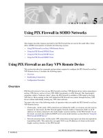
Figure 3-11. Physical Addressing of Data Between Hosts
[View full size image]
The process in Figure 3-11
is as follows:
1. Host A logically addresses the data for Host B but physically addresses it to
00:05:9A:3C:78:00, the router interface physical address.
2. The router receives the data, because it is physically addressed to it, but realizes
that logically it must be delivered to Host B. Therefore, it rebuilds the frame, using
the physical address of the interface on the same network as Host B
(00:05:9A:3C:78:01) and physically addresses it to 00:05:9A:3C:78:30.
Logical Addresses
Logical addresses are the counterpart to physical addresses and allow for the
identification of hosts and the delivery of data to hosts regardless of physical location or
proximity to each other. Consequently, logical addresses must have a true global
significance, and must be unique within all interconnected network segments. TCP/IP
uses IP addresses as the logical addressing method. The following sections look at IP
addresses in more detail.
IP Addressing
An IP address is a 32-bit universal identifier that provides a means of uniquely
identifying from a global perspective. What we mean by global perspective is that the
address is unique on all interconnected networks, such as all internal networks in an
organization, or in a truly global sense on all networks across the Internet.
The 32-bit IP address is separated into four 8-bit octets, allowing each octet to have a
value ranging from 0 to 255. Furthermore, the IP address is logically separated into two
distinct components: the network ID and the host ID. The network ID is used to identify
the subnet upon which the host resides. The host ID is used to identify the host itself
within the given subnet.
IP addresses can be displayed in three typical formats:
•
Binary notation Binary notation is the format that systems on the network use to
process the address. An example of binary notation is
11000000.10101000.00000001.01100100.
•
Hexadecimal notation Hexadecimal notation is the format typically used when
identifying IPv6 addresses. An example of hexadecimal notation of an IPv4
address is C0.A8.01.64
•
Dotted-decimal notation Dotted-decimal notation is the format that is typically
used for displaying the IP address in a human-readable format. An example of
dotted-decimal notation is 192.168.1.100.
IP Address Classes
Not all networks are the same size. Some are smaller than others; some are larger than
others. To provide a hierarchy and structure to the assignment of IP addresses, they were
broken down into distinct classes, with each class natively supporting a different number
of networks and hosts.
For the public IP address space, which is managed by the IANA, three classes of
addresses were defined:
•
Class A addresses Class A addresses provide for 128 (2
7
) total networks, with each
network containing 16,777,216 (2
24
) hosts. This is achieved by designating the
first octet as the network ID and the remaining 3 octets as the host ID. Class A
addresses can be identified by the first bit of the first octet, which must be a 0,
providing for a range of first octet values from 1 to 126 because the values of 0
and 127 are unusable (because 0 is all 0s and 127 is reserved for use as a loopback
address).
•
Class B addresses Class B addresses provide for a greater number of network IDs
at the cost of the total number of hosts per network. For the Class B address space,
the first 2 octets are designated as network ID, and the last 2 octets are designated
as the host ID. Class B addresses can be identified by the fact that the first 2 bits o
f
the first octet must be a 10. This allows for the total number of network IDs to be
16,384 (or 2
14
because the first 2 bits are defined) and the total number of hosts per
network to be 65,536 (2
16
). This provides a first octet range of values from 128 to
191.
•
Class C addresses Class C addresses provide for an extremely large number of
networks, with a small number of hosts per network. For the Class C address
space, the first 3 octets are designated as network ID, and the last octet is
designated as host ID. Class C addresses can be identified by the fact that the first
3 bits of the first octet must be 110, which provides for a first octet range of values
from 192 to 223. This provides for 2,097,152 total networks (2
21
) with each
network containing 256 host IDs (2
8
).
In addition to the public address space, there are two additional address spaces,
one for use in multicasting and the other for future use and testing:
•
Class D addresses Class D addresses are identified by the first 4 bits of the first
octet having a value of 1110, which allows for a range of values in the first octet
of 224 to 239. Unlike the public address space, which is designed to allow an IP
address to be assigned to and represent the host on the network, the Class D
addresses are used to assign multicast addresses (addresses that may be assigned to
multiple hosts allowing them to receive the same data without the data needing to
be transmitted uniquely to each host). In addition, Class D addresses have no
network or host portion of the address, leaving the remaining 28 bits of the address
to be the multicast address.
•
Class E addresses Class E addresses are identified by the first 4 bits of the first
octet having a value of 1111, which allows a range of values in the first octet of
240 to 255. This address space should not be used in any circumstance. The
address of 255.255.255.255 is used to indicate an "all subnets" broadcast.
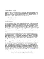
Figure 3-12
shows the different address classes.
Figure 3-12. Address Classes
Classless Interdomain Routing (CIDR)
Although the classful address space is a great idea, the truth is that not everyone needs
networks with the number of hosts that each class of address provides. For example, if
you have more than 255 hosts that you need to connect to a network, using the classful
address space you have to bump up to a full Class B, providing for 65,534 hosts on the
network. Obviously, that is far more hosts than is necessary. To address this deficiency,
CIDR was implemented.
One of the benefits of classful addresses is that they provide a hierarchy to the network
through the use of the network ID. This translates into an efficient routing environment
because it is easy for a router to determine what networks can be grouped together and
treated as a single routing entry. CIDR adheres to this philosophy while allowing for
administrators to create additional networks regardless of address class by using a strict
interpretation of the subnet mask as the means of identifying a network. The subnet mask
is used to determine the network prefix, which defines where the network ID portion of a
given IP address ends. For example, a default Class B address (let's say 172.16.0.0) uses
a network prefix of /16, or 16 bits. However, using CIDR, the administrator can elect to
assign 20 bits of the IP address to the network, resulting in a network prefix of /20. This
allows an administrator that has been assigned a single Class B address space to
effectively turn that single network (172.16.0.0) into 16 individual networks (the result of
2
4
, or the 4 additional bits that were borrowed from the host ID portion of the address and
given to the network portion of the address). Similarly, because 4 bits have been taken
from the host ID of the address, this leaves a total 12 bits for host ID assignment. This
results in each of the 16 networks that were created having the potential for a maximum
of 4096 hosts per network (2
12
).
Note
As you have read through this chapter, you may have noticed the use of (2
x
) when
referring to the number of hosts per network. This is the technically accurate
representation of hosts per network. However, most networks reserve a host ID to
identify the subnet itself (a host ID that consists of all 0s) as well as the broadcast ID for
the subnet (a host ID that consists of all 1s). Consequently, the number of usable hosts
per subnet is typically represented as (2
x
) -2 to account for the loss of those two host IDs.
Subnets
Throughout this section, I have mentioned subnets repeatedly, but what is a subnet and
why are they important to firewalls? A subnet is nothing more than a group of IP
addresses that are on the same network ID. By extension, a subnet is the collection of
hosts that are on the same network segment. Subnets allow us to dissect the network into
small, easier-to-manage chunks. The reason for this is simple: The fewer the number of
hosts on a given subnet, the less extraneous the traffic and the smoother the flow of
traffic will go because there are not as many hosts in contention with each other.
For communications to occur between subnets, a router needs to be involved. Routers