Đo lường quang học P5
Bạn đang xem bản rút gọn của tài liệu. Xem và tải ngay bản đầy đủ của tài liệu tại đây (456.8 KB, 47 trang )
5
Light Sources and Detectors
5.1 INTRODUCTION
The most important ‘hardware’ in optical metrology is light sources and detectors. To
appreciate the various concepts of these devices, we first introduce the different units and
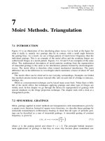
terms for the measurement of electromagnetic radiation. Then the laser is given a relatively
comprehensive treatment. The description of detectors involves some understanding of
semiconductor technology. Therefore a brief introduction to semiconductors is given in
Appendix E. Because of the increasing use of the CCD camera in optical metrology, this
device is described separately in Section 5.8.
5.2 RADIOMETRY. PHOTOMETRY
To compare light sources we have to make a brief introduction to units and terms for the
measurement of electromagnetic radiation (Slater 1980; Klein and Furtak 1986; Longhurst
1967). Below we present the most common radiometric units.
Radiant energy, Q, is energy travelling in the form of electromagnetic waves, measured
in joules.
Radiant flux, = ∂Q/∂t is the time rate of change, or rate of transfer, of radiant
energy, measured in watts. Power is equivalent to, and often used instead of, flux. Radiant
flux density at a surface, M = E = ∂/∂A, is the radiant flux at a surface divided by the
area of the surface. When referring to the radiant flux emitted from a surface it is called
radiant exitance M. When referring to the radiant flux incident on a surface it is called
irradiance E. Both are measured in watts per square metre. Note that in the rest of this
book, we use the term intensity, which is proportional to irradiance.
Radiant intensity, I = ∂/∂, of a source is the radiant flux proceeding from the
source per unit solid angle in the direction considered, measured in watts per steradian.
Radiance, L = ∂
2
/∂∂Acos θ, in a given direction, is the radiant flux leaving an
element of a surface and propagated in directions defined by an elementary cone containing
the given direction, divided by the product of the solid angle of the cone and the area
of the projection of the surface element on a plane perpendicular to the given direction.
Figure 5.1 illustrates the concept of radiance. It is measured in watts per square metre
and steradian.
Optical Metrology. Kjell J. G
˚
asvik
Copyright
2002 John Wiley & Sons, Ltd.
ISBN: 0-470-84300-4
100
LIGHT SOURCES AND DETECTORS
Surface
normal
P
d
A
dΩ
q
Figure 5.1 The concept of radiance
Table 5.1 Symbols, standard units and defining equations for fundamental radiometric and pho-
tometric quantities
Symbol Radiometric
quantity
Radiometric
units
Defining
equation
Photometric
quantity
Photometric
units
Q Radiant energy J Luminous energy lm s
Radiant flux W = ∂Q/∂t Luminous flux lm
M Radiant
exitance
Wm
−2
M = ∂/∂A Luminous
exitance
lm m
−2
E Irradiance W m
−2
E = ∂/∂A Illuminance lm m
−2
I Radiant
intensity
Wsr
−1
I = ∂/∂ Luminous
intensity
lm sr
−1
LRadiance Wsr
−1
m
−2
L = ∂
2
/∂∂A cos θ Luminance lm sr
−1
m
−2
All of the radiometric terms have their photometric counterparts. They are related to
how the (standard) human eye respond to optical radiation and is limited to the visible part
of the spectrum. In Table 5.1 we list the radiometric and the corresponding photometric
quantities.
To distinguish radiometric and photometric symbols they are given subscripts e and v
respectively (e.g. L
e
= radiance, L
v
= luminance).
The radiometric quantities refer to total radiation of all wavelengths. A spectral version
for each may be defined by adding the subscript λ (e.g. M
eλ
or simply M
λ
) where for
example a spectral flux
λ
dλ represents the flux in a wavelength interval between λ and
λ + dλ, with units watts per nanometre (Wnm
−1
) or watt per micrometre (W µm
−1
).
To represent the response of the human eye, a standard luminosity curve V(λ)has been
established, see Figure 5.2. It has a peak value of unity at λ = 555 nm. The conversion
RADIOMETRY. PHOTOMETRY
101
200
0
0.1
0.2
0.3
0.4
0.5
0.6
0.7
0.8
0.9
1.0
300 400 500 600 700 800 900
Wavelength (nm)
V
(l)
Figure 5.2 The standard luminosity curve
at λ = 555 nm is standardized to be
K
m
= 680 lm/W (5.1)
This means that 1 W of flux at 555 nm gives the same physical sensation as 680 lm. For
other wavelengths the conversion factor is
K = K
m
V(λ)= 680 V(λ)lm/W (5.2)
We may use Equation (5.2) to convert any radiometric quantity to the corresponding
photometric quantity. For instance, if we have a spectral radiant flux
eλ
, the luminous
flux is given by
v
= 680
∞
0
V(λ)
eλ
dλ(5.3)
An average conversion factor is defined by
K
av
=
v
/
e
(5.4)
102
LIGHT SOURCES AND DETECTORS
5.2.1 Lambertian Surface
A Lambertian surface is a perfectly diffuse reflecting surface defined as one which the
radiance L is constant for any angle of reflection θ to the surface normal. Lambert’s
cosine law states that the intensity (flux per unit solid angle) in any direction varies as
the cosine of the reflection angle:
I = I
0
cos θ(5.5)
Since the projected area of the source also varies as cos θ, the radiance becomes inde-
pendent of the viewing angle:
L =
I
dA cos θ
=
I
0
dA
(5.6)
Assume that an elemental Lambertian surface dA is irradiated by E in W m
−2
and that
the radiant flux reflected in any direction θ to the surface normal is given by the basic
equation
d
2
= L d dA cos θ(5.7)
The solid angle d in spherical coordinates (see Figure 5.3) is given by
d = (r sin θ dθr dφ)/r
2
= sin θ dθ dφ(5.8)
The total radiant flux reflected into the hemisphere therefore is given by
d
h
=
2π
0
dϕ
π/2
0
L dA cos θ sin θ dθ = πLdA(5.9)
d
A
dq
q
r
dq
r
sin q
r
Figure 5.3
RADIOMETRY. PHOTOMETRY
103
The ratio of the total reflected radiant flux to the incident radiant flux d
i
= EdA defines
the diffuse reflectance of the surface
d
h
d
i
= ρ =
πL
E
(5.10)
The quantity ρE is the radiant flux density reflected from the surface which is equivalent
to the radiant exitance M of a self-emitting source, giving
M = πL (5.11)
for a Lambertian surface.
For non-Lambertian surfaces, L is a function of both θ and the azimuthal angle φ and
therefore can not be taken outside the integral in Equation (5.9). Many natural surfaces
show Lambertian characteristics up to θ = 40
◦
. In satellite observations, one has found
snow and desert to be Lambertian up to about 50
◦
or 60
◦
. Most naturally occurring
surfaces depart significantly from the Lambertian case for θ greater than about 60
◦
,an
exception is White Sands, the desert in New Mexico, which is nearly Lambertian for all
angles.
5.2.2 Blackbody Radiator
A blackbody at a given temperature provides the maximum radiant exitance at any wave-
length that any body in thermodynamic equilibrium at that temperature can provide. It
follows that a blackbody is a Lambertian source and that it is a perfect absorber as well as
a perfect radiator. The spectral radiant exitance M
λ
from a blackbody is given by Planck’s
formula
M
λ
=
2πhc
2
λ
5
[exp(hc/λkT ) − 1]
(5.12)
where
h = Planck’s constant = 6.6256 × 10
−34
Js;
c = velocity of light = 2.997925 × 10
8
ms
−1
;
k = Boltzmann’s constant = 1.38054 × 10
−23
JK
−1
;
T = absolute temperature in kelvin;
λ = wavelength in metres.
which gives M
λ
in W m
−2
µm
−1
. Figure 5.4 shows M
λ
as a function of wavelength for
different temperatures.
By integrating over all wavelengths we get the Stefan–Boltzmann law
M =
∞
0
M
λ
dλ = σT
4
(5.13)
where σ = (2π
5
k
4
)/(15c
2
h
3
) = 5.672 × 10
−8
Wm
−2
K
−4
is called the Stefan–Boltz-
mann constant.
104
LIGHT SOURCES AND DETECTORS
100 200 400 6001000 10 000
l
m
T
= 2898 µm K
10 000 K
200 K
300 K
500 K
1000 K
2000 K
6000 K
10
−1
10
2
10
3
10
4
10
5
10
6
10
7
10
8
10
9
10
10
10
1
Wavelength (nm)
Radiant exitance (Wm
−2
µm
−1
)
Figure 5.4 Spectral radiant exitance from a blackbody at various temperatures according to
Planck’s law
By differentiating Equation (5.12) we get the wavelength λ
m
for which M
λ
is peaked
λ
m
T = 2897.8 µmK (5.14)
This relation is called Wien’s displacement law.
The blackbody is an idealization. In nature most radiators are selective radiators, i.e.
the spectral distribution of the emitted flux is not the same as for a blackbody. Emissitivity
is a measure of how a real source compares with a blackbody and is defined as
ε = M
/M (5.15)
where M
is the radiant exitance of the source of interest and M is the radiant exitance
of a blackbody at the same temperature. ε is a number between 0 and 1 and is in general
both wavelength and temperature dependent. When ε is independent of wavelength the
source is called a greybody. A more general form of Equation (5.15) can be written to
take into account the spectrally varying quantities, thus ε, the emissivity for a selective
radiator, as an average over all wavelengths is
ε =
M
M
=
∞
0
ε(λ)M
λ
dλ
∞
0
M
λ
dλ
=
1
σT
4
∞
0
ε(λ)M
λ
dλ(5.16)
Consider two slabs of different materials A and B, and that each is of semi-infinite
thickness and infinite area, forming a cavity as shown in Figure 5.5. Assume that A is a
RADIOMETRY. PHOTOMETRY
105
A
B
M
M
bb
r
M
bb
Figure 5.5 Radiant exitances between a blackbody A and another material B
blackbody and that B is a material with emissivity ε,reflectanceρ and absorbtance α,and
that the materials and cavity are in thermal equilibrium. Because of the last assumption,
the flux onto B must equal the flux leaving B toward A. Thus
M
bb
= ρM
bb
+ M(5.17)
where M
bb
and M are the radiant exitance of A (the blackbody) and B respectively. From
the definition of emissivity we have
M/M
bb
= ε = 1 − ρ(5.18)
which is referred to as Kirchhoff’s law.
Because of conservation of energy, the reflectance, transmittance and absorbance at
a surface add up to unity. Since we have assumed semi-infinitely thick materials, the
transmittance is zero and we have
M/M
bb
= ε = 1 − ρ = α(5.19)
where α is the absorptance of material B. Equation (5.19) states that good emitters and
absorbers are poor reflectors and vice versa. We can anticipate that Equation (5.19) holds
for any given spectral interval which gives the more general form
M
λ
/M
λbb
= ε(λ) = 1 − ρ(λ)= α(λ) (5.20)
5.2.3 Examples
Let us compare the light from a typical He–Ne laser and a blackbody with the same
area as the output aperture of the laser. Assume this area to be 1 mm
2
and the blackbody
temperature to be 3000 K, close to the temperature of the filament of an incandescent
lamp. From Equation (5.13) we find the blackbody exitance to be 4.6 × 10
6
Wm
−2
which
gives a radiant flux of 4.6 W. An ordinary He–Ne laser has an output of about 1/1000th
of this, not very impressive even if we take into account that most of the radiation from
the blackbody is outside the visible region.
From Equation (5.11) we find the radiance from the blackbody to be
L = M/π = 1.46 × 10
6
Wm
−2
sr
−1
106
LIGHT SOURCES AND DETECTORS
The light beam from the laser has a diverging angle of about λ/d where λ is the wave-
length and d is the output aperture diameter. This gives a solid angle of about λ
2
/A where
A is the aperture area. The radiance at the centre of the beam is therefore (cos θ = 1)
L =
A
=
λ
2
(5.21)
With a radiant power (flux) = 5 mW and a wavelength λ = 0.6328 µm, this gives
L = 1.2 × 10
10
Wm
−2
sr
−1
, a number clearly in favour of the laser. Note that the radiance
of the blackbody is independent of its area. By decreasing the power of the laser by
reducing its output aperture, the radiance decreases accordingly.
Figure 5.6 illustrates the imaging of an object of elemental area dA
o
by a lens system
with the entrance and exit pupils as sketched. We assume that the object is a Lambertian
surface of radiance L
o
. The flux incident over an annular element of the entrance pupil
is given by
d
2
= L
o
dA
o
cos θ d(5.22)
where
d = 2π sin θ dθ(5.23)
If θ
m
is the angle of the marginal ray passing through the entrance pupil, the flux incident
over the entrance pupil is
d
o
= 2πL
o
dA
o
θ
m
0
sin θ cos θ dθ = πL
o
dA
o
sin
2
θ
m
(5.24)
Equation (5.24) is not the product of radiance, area and solid angle, or 2πL
o
dA
o
(1 −
cos θ
m
), as we might at first expect, because the cosine factor, which accounts for the
projected area in any direction in the solid angle, has to be included in the integration.
We can write a similar expression for the flux d
i
incident over the exit pupil from a
fictitious Lambertian source L
i
, in the plane of the image. Then, evoking the principle of
q
q
m
d
A
o
dΩ′
dΩ
d
A
i
Entrance
pupil
Exit
pupil
q′
q′
m
Figure 5.6 Geometry for determining the radiometry of an optical system
RADIOMETRY. PHOTOMETRY
107
the reversibility of light, we can say that this flux, leaving the exit pupil in the direction
of the image, gives rise to an image plane radiance L
i
according to
d
i
= πL
i
dA
i
sin
2
θ
m
(5.25)
where dA
i
is the image area and θ
m
is the inclination of the marginal ray in image space.
For a perfect lossless system (that is, one without reflection, absorption and scattering
losses), d
o
= d
i
,so
L
i
sin
2
θ
m
dA
i
= L
o
sin
2
θ
m
dA
o
(5.26)
Now
dA
i
dA
o
= m
2
(5.27)
the square of the lateral magnification. We assume that the lens is aplanatic, obeying the
Abbe sine condition, that is, it exhibits zero spherical abberation and coma for objects
near the axis, no matter how low the F -number. (Spherical abberation is illustrated in
Figure 2.10). Thus,
n sin θ
m
= mn
sin θ
m
(5.28)
where n and n
are the refractive indices in object and image space which we set equal
to unity. Then
sin θ
m
sin θ
m
= m(5.29)
and we get L
i
= L
o
which shows that the radiance is conserved in a lossless imaging
system.
Equation (5.25) then gives for the image irradiance
E
i
= d
i
/dA
i
= πL
o
sin
2
θ
m
(5.30)
As usual in paraxial optics, we approximate sin θ
m
by tan θ
m
, giving
sin θ
m
≈ tan θ
m
=
D
i
2b
(5.31)
where D
i
is the diameter of the exit pupil and b is the image distance. By introducing
the aperture number F = f/D
i
where f is the focal length, Equation (5.30) becomes
E
i
= πL
o
D
i
2b
2
=
πL
o
4F
2
(1 + m)
2
(5.32)
With the object at infinity, b = f and we get
E
i
= πL
o
D
i
2f
2
=
πL
o
4F
2
(5.33)
108
LIGHT SOURCES AND DETECTORS
Equation (5.33) or a similar form of it, is generally referred to as the ‘camera equation’. It
indicates that image irradiance is inversely proportional to the square of the F -(aperture)
number. Therefore the diaphragm or stop openings for a lens are marked in a geometrical
ratio of 2
1/2
.
Recall that we have assumed the object to be a Lambertian surface. For example, for
a point source of radiant intensity I as the object, the flux intercepted by the entrance
pupil is
d = I d =
IS
a
2
= Iπ
D
2a
2
(5.34)
where S is the area and D is the diameter of the entrance pupil, a is the object dis-
tance and where we for simplicity assume the entrance and exit pupils to have equal
area S.
If we take the image area dA
i
to be equal to the area of the Airy disc (see Section 4.6,
Equation (4.33))
dA
i
= π(r
i
)
2
= 1.5π
λb
D
2
(5.35)
we get for the image irradiance
E
i
=
d
dA
i
=
8
3
I
λ
2
D
2a
2
D
2b
2
=
I
6λ
2
m
F
2
(1 + m)
2
2
(5.36)
From this expression we see that the image irradiance is dependent on both the object
and image distances. In conclusion we might say that for a Lambertian surface we can
not increase the image irradiance by placing the lens closer to the object, but for a point
source we can, the maximum occurring at unit magnification, i.e. when a = b = 2f .
5.3 INCOHERENT LIGHT SOURCES
Most light sources are incoherent, from the candle light to the Sun. They all radiate light
due to spontaneous emission (see Section 5.4.1). Here we will consider some sources
often used in scientific applications. These are incandescent sources, low-pressure gas
discharge lamps and high-pressure gas discharge-arc lamps. They are commonly rated,
not according to their radiant flux, but according to their electric power consumption.
Tungsten halogen lamps
Quartz tungsten halogen lamps (QTH) produce a bright, stable, visible and infrared output
and is the most commonly applied incandescent source in radiometric and photometric
studies. It emits radiation due to the thermal excitation of source atoms or molecules. The
spectrum of the emitted radiation is continuous and approximates a blackbody. Spectral
distribution and total radiated flux depend on the temperature, area and emissivity. For
a QTH lamp, the temperature lies above 3000 K and the emissivity varies around 0.4 in
the visible region.
COHERENT LIGHT SOURCES
109
In all tungsten filament lamps, the tungsten evaporates from the filament and is deposi-
ted on the inside of the envelope. This blackens the bulb wall and thins the tungsten
filament, gradually reducing the light output. With tungsten halogen lamps, the halogen
gas effectively removes the deposited tungsten, and returns it to the hot filament, leaving
the inside of the envelope clean, and greatly increases lamp life. This process is called the
halogen cycle. A commercial 1000 W QTH lamp have a luminous flux of up to 30 000 lm
with a filament size of 5 mm × 18 mm (Oriel Corporation 1994).
Low-pressure gas-discharge lamps
In these sources an electric current passes through a gas. Gas atoms or molecules become
ionized to conduct the current. At low current density and pressures, electrons bound to
the gas atoms become excited to well-defined higher-energy levels. Radiation is emitted
as the electron falls to a lower energy level characteristic of the particular type of gas.
The spectral distribution is then a number of narrow fixed spectral lines with little back-
ground radiation. The known wavelengths determined by the energy levels are useful for
calibration of spectral instruments.
High-pressure gas-discharge arc lamps
High-current-density arc discharges through high-pressure gas are the brightest conven-
tional sources of optical radiation. Thermal conditions in the arc are such that gas atoms
(or molecules) are highly excited. The result is a volume of plasma. The hot plasma emits
like an incandescent source, while ionized atoms emit substantially broadened lines. The
spectral distribution of the radiation is a combination of both the continuum and the line
spectra. The most common sources of this type are the Xenon (Xe) and mercury (Hg)
short arc lamps. Xenon lamps have colour temperatures of about 6000 K, close to that of
the Sun. A commercial 1000 W Hg lamp produces a luminous flux of 45 000 lm with an
effective arc size of 3 mm × 2.6 mm. A commercial 1000 W Xe lamp is even brighter
with luminous flux of 30 000 lumens with an effective arc size of 1 mm × 3mm(Oriel
Corporation 1994).
5.4 COHERENT LIGHT SOURCES
5.4.1 Stimulated Emission
Figure 5.7 shows an energy-level diagram for a fictive atom or molecule (hereafter called
an atom). Here only four levels are shown. Assume that the atom by some process is
raised to an excited state with energy E
3
. Then the atom drops to energy levels E
2
, E
1
and E
0
in successive steps. E
0
may or may not be the ground state of the atom. We do
not specify the type of transition from E
3
to E
2
and from E
1
to E
0
, but assume that the
energy difference between E
2
and E
1
is released as electromagnetic radiation of frequency
ν given by
E
2
− E
1
= hν (5.37)
110
LIGHT SOURCES AND DETECTORS
E
3
E
0
E
2
E
1
h
n
Figure 5.7 Energy-level diagram of a fictitious atom
Population
Energy levels
Energy
(a) (b)
Energy
Population
Population inversion
between these levels
Figure 5.8 Distribution of populations among energy levels at (a) equilibrium and (b) during a
population inversion
where h = 6.6256 × 10
−34
J s is the Planck constant. This might be the situation in an
ordinary light source (e.g. a discharge lamp) where the transition occurs spontaneously
and the photon is therefore said to be created by spontaneous emission.
As postulated by Einstein, also another type of transition is possible: if a photon of
frequency given by Equation (5.37) passes the atom it might trigger the transition from
E
2
to E
1
thereby releasing a new photon of the same frequency by so-called stimulated
emission. Under normal conditions known as thermodynamic equilibrium, the number of
atoms in a state tends to decrease as its energy increases as shown in Figure 5.8(a). This
means that there will be a larger population in the lower state of a transition than in the
higher state. Therefore photons passing the atom are far more likely to be absorbed than
to stimulate emission. Under these conditions, spontaneous emission dominates.
However, if the excitation of the atoms is sufficiently strong, the population of the upper
level might become higher than that of the lower level. This is called population inversion
and is illustrated in Figure 5.8(b). Then by passing of a photon of frequency given by
Equation (5.37), it will be more likely to stimulate emission from the excited state than to
be absorbed by the lower state. This is the condition that must be obtained in a laser and
the result is laser gain or amplification, a net increase in the number of photons with the
transition energy. Light amplification by the stimulated emission of radiation therefore has
COHERENT LIGHT SOURCES
111
given rise to the acronym ‘laser’. Laser gain is proportional to the difference between the
chance of stimulated emission and the chance of absorption. Therefore the population of
both the upper and lower levels of the laser transition are important. Thus if laser action
is to be sustained, the lower level must be depopulated as the upper level is populated
or the population inversion will end. That is indeed what happens in some pulsed lasers.
Stimulated emission has the same wavelength as the original photon and it is in phase
(or coherent) with the original light.
In the description given above, four energy levels are involved. This is the best con-
dition for laser action and is called a four-level laser. But also three-level lasers exists
which is the case when e.g. the lower transition level is the ground state. To maintain
population inversion, it is easily realized that the lifetime of the E
2
-level should be as long
as possible and the lifetime of the E
1
-level should be as short as possible. The process
of raising the atom to the E
3
excited level is called pumping. The pumping mechanism
is different for different laser types.
In the description given above, we have assumed laser transition between energy levels
E
2
and E
1
only. Usually, stimulated emission can be obtained between many different
energy levels in the same laser medium. Dependent on the construction of the laser, one
can obtain lasing from a single transition or from a multitude of transitions.
Laser amplification can occur over a range of wavelengths because no transition is
infinitely narrow. The range of wavelengths at which absorption and emission can occur
is broadened by molecular motion (Doppler broadening) vibrational and rotational energy
levels, and other factors.
To be more specific, let us consider the most familiar of all lasers, the helium–neon
(He–Ne) laser.
Figure 5.9 shows the construction of a typical He–Ne laser. Inside a discharge tube is a
gas mixture of helium and neon. Typically the mixture contains 5 to 12 times more helium
than neon. By applying voltage to the electrodes, the resulting electric field will accelerate
free electrons and ions inside the tube. These collide with helium atoms raising them to
a higher energy level. By collision between helium and neon atoms, the latter are raised
to a higher energy level. This constitute the pumping process. The neon atoms, which
constitute the active medium, return to a lower energy level and the energy difference is
released as electromagnetic radiation.
Figure 5.10 shows an energy-level diagram for an He–Ne laser emitting red light.
Excited helium atoms in the 1s2s state transfer energy to neon atoms in the ground state
by collisions, exciting the neon atoms to the 5s excited state. By returning to the 3p state
the energy difference is released as light of wavelength 632.8 nm.
Brewster
window
Anode
E
q
p
Cathode
DC
power
supply
Discharge tube
Mirror
Figure 5.9 He–Ne laser. (Hecht & Zajac, Optics,
1974, Addison-Wesley Publishing Company,
Inc., Reading, Massachusetts. Figure 14.31. Reprinted with permission)
112
LIGHT SOURCES AND DETECTORS
1s
2
Ground state
Electron
impact
Collision
Helium
Metastable
20.61 eV
1s2s
5s
4s
3s
2p
4p
3p
20.30 eV
18.70 eV
632.8 nm laser
20.66 eV
19.78 eV
16.70 eV
Diffusion
to walls
Ground state
Neon
Figure 5.10 He– Ne laser energy levels
Population inversion alone is sufficient to produce ‘light amplification by the stimulated
emission of radiation’, but the result is only a coherent monochromatic light bulb. In
fact, population inversion is observed in the atmosphere of Mars. To get light oscillation
however, the discharge tube is enclosed in an optical cavity or resonator which is two
mirrors facing each other as in Figure 5.9. The result is that the light is reflected back and
forth through the tube, stimulating emission again and again from neon atoms. Emission
in other directions is lost out of the laser medium and the light is concentrated in a beam
oscillating back and forth between the mirrors. The optical cavity therefore acts as an
oscillator or feedback amplifier and is an essential part of a laser.
Below we give a short description of other lasers. Numerous lasers and laser media
have been demonstrated in the laboratory. Here we concentrate on lasers which are avail-
able commercially. For further details, the excellent book by Hecht (1992) is highly
recommended.
There are many potential criteria for classifying lasers, but the two most useful ones are
the type of active medium and the way in which it is excited (pumped). Usual practice is
to group most devices as gas, liquid, solid-state or semiconductor lasers. A few important
lasers are exceptions. Liquid- and solid-state lasers are pumped optically, i.e. by means
of a flashlamp or another laser. Semiconductor lasers are excited when charge carriers
in a semiconductor recombine at the junction of regions doped with n- and p-type donor
materials. Gas lasers can be pumped in various ways, including discharge excitation (cf.
the He–Ne laser), radio frequency (RF) excitation, chemical and optical excitation and
also by gas expansion (gas dynamics).
5.4.2 Gas Lasers
Helium–neon
Among the first lasers demonstrated and the first gas laser (Javan et al. 1961). The
632.8 nm line is the most important because it can give up to about 50 mW continuous
COHERENT LIGHT SOURCES
113
wave (c.w.). Green, yellow, orange and multiline versions are being offered commercially.
Advantages: Output beam of low divergence and high coherence.
Noble gas ion lasers
Emit on ionized rare gas lines. Pumping: Electrical discharge. The most important is argon
with strong lines in the blue-green and weaker lines in the ultraviolet and near-infrared.
The 514.5 nm line is the strongest in larger water-cooled lasers while the 488.0 nm line
is the strongest in small air-cooled models. Another type is Krypton lasers.
Advantages: Their ability to produce c.w. output of a few milliwatts to tens of watts
in the visible and up to 10 W in the ultraviolet.
Helium–cadmium lasers
Emit on lines of ionized metal vapours. Electric discharge pumping. C.w. output up to
about 150 mW at 442 nm or powers to about 50 mW at 325 nm.
Advantages: Offer short wavelength at moderate output power which can be focused
to a small spot.
Carbon dioxide lasers
Pumping: Electric discharge, RF or gas-dynamic. Transitions between vibrational levels.
Infrared radiation between 9 and 11 µm. Several distinct types. Can produce c.w. output
powers from under 1 W for scientific applications to many kilowatts for materials working.
Can generate pulses from the nanosecond to millisecond regimes. Custom-made CO
2
lasers have produced c.w. beams of hundreds of kilowatts for military weapon research
or nanosecond pulses of 40 kJ for research in laser-induced nuclear fusion. Advantages:
No other commercial laser can generate as intense c.w. output.
Chemical lasers
Pumping by means of chemical reaction. Three most important media: hydrogen fluoride,
deuterium fluoride and iodine. Emits at wavelengths between 1.3 µmand4.2 µm. Mil-
itary research has demonstrated building-sized lasers that have generated nominally c.w.
outputs to a couple of megawatts. Commercial devices produce much lower powers.
Copper and gold vapour lasers
Emit in or near the visible region on lines of neutral metal vapor. Pumping: Electric
discharge. Operate as pulsed lasers only. Commercial copper vapour lasers can emit over
100 W in the green and yellow, gold vapour lasers can generate several watts in the
114
LIGHT SOURCES AND DETECTORS
red. Advantages: High power and high efficiency in the actual wavelength region with
repetition rates of several kilohertz.
Eximer lasers
Eximer is a contraction of ‘excited dimer’, a description of a molecule consisting of two
identical atoms which exists only in an excited state, e.g. He
2
and Xe
2
. Since the ground
state does not exist, population inversion is obtained as long as there are molecules in
the excited state. Pumping: Electric discharge transverse to the gas flow. Most important
media: rare gas halides such as: argon fluoride, krypton fluoride, xenon fluoride and xenon
chloride. Emit powerful pulses (average power of up to 100 W) lasting nanoseconds or
tens of nanoseconds in or near the ultraviolet.
Advantages: Very high gain. No other commercial laser can generate such high average
power at such a short wavelength.
Nitrogen lasers
Pumping: Electric discharge. Can produce nanosecond or subnanosecond pulses (average
power of a few hundred milliwatts) of wavelength 337 nm.
Advantages: Low-cost. So simple to build that it was once featured in the ‘Amateur
Scientist’ column of Scientific American.
5.4.3 Liquid Lasers
Dye lasers
The discussion of liquid lasers almost invariably starts and ends with the dye laser. The
active medium is a fluorescent organic dye dissolved in a liquid solvent.
Pumping: Optical, with a flashlamp or (more often) with an external laser. The output
wavelength can be tuned from the near-ultraviolet into the near-infrared. Dye lasers can
be adjusted to operate over an extremely narrow spectral bandwidth and can also produce
ultrashort pulses, much shorter than a picosecond.
Disadvantages: Very complex. Tuning wavelength across the visible spectrum requires
several changes of dye. Complex optics are needed to produce either ultra-narrow
linewidth or picosecond pulses.
5.4.4 Semiconductor Diode Lasers. Light Emitting Diodes
As mentioned in Appendix E, light can be emitted from a semiconductor material as
a result of electron-hole recombination. A light-emitting diode (LED) is a forward-
biased p-n junction where electrons and holes are injected into the same region of
space. The resulting recombination radiation is called injection electroluminescence (see
Figure 5.11a). If the forward voltage is increased beyond a certain value, the number
COHERENT LIGHT SOURCES
115
+−
pn
pn
+−+−
p
n
(a) (b) (c)
Figure 5.11 A forward-biased semiconductor p-n junction diode operated as (a) an LED; (b) a
semiconductor optical amplifier; and (c) a semiconductor injection laser. From Saleh, B.E.A., and
Teich, M.C. (1991) Fundamentals of Photonics. Reproduced by permission of John Wiley & Sons,
New York
of electrons and holes in the junction region can become sufficiently large so that pop-
ulation inversion is achieved. We then can have stimulated emission and the junction
may be used as a diode laser amplifier (Figure 5.11(b)) or, with appropriate feedback, as
an injection laser diode (Figure 5.11(c)). Both LEDs and injection lasers are highly effi-
cient electronic-to-photonic transducers and are readily modulated by the injected current.
Their successful applications include lamp indicators, display devices, scanning, reading
and printing systems, fibre-optic communication systems and optical data storage systems
such as CD players.
LEDs. The photon flux generated in the junction is radiated uniformly in all directions.
However, because of the high refractive index of many semiconductor materials (for
GaAs, n = 3.6) most of the light suffers total internal reflection (see Section 9.5). Thus,
for n = 3.6, only 3.9% of the total generated photon flux can be transmitted. A technique to
increase the output flux is to encapsulate the junction in a plastic material with a refractive
index of about 1.5. LEDs may be constructed in either surface or edge-emitting configu-
ration: see Figure 5.12. Figure 5.13 shows the observed wavelength spectral densities for
a number of LEDs that operate in the visible and near-infrared regions.
In a semiconductor injection laser (or laser diode, LD) the feedback is usually obtained
by cleaving the semiconductor material along its crystal planes. The sharp refractive index
difference between the crystal and the surrounding air causes the cleaved surfaces to act
as reflectors. In comparison with other types of lasers, the laser diode has a number of
advantages: small size, high efficiency, integrability with electronic components, and ease
of pumping and modulation by electric current injection. However, the spectral linewidth
of LDs is typically larger than that of other lasers.
If the thickness of the active region (the junction) could be reduced, the optical gain
would be the same with a far lower current density. This is a problem, however, because
116
LIGHT SOURCES AND DETECTORS
(a) (b)
Figure 5.12 (a) Surface-emitting LED and (b) edge-emitting LED
0.3 0.4 0.5 0.6 0.7 0.9 1.0 1.1 1.2 1.3
Wavelength λ
0
(µm)
Violet
GaN
Green
GaP:N
Yellow
GaAs
.14
P
.86
Orange
GaAs
.35
P
.65
Red
GaP:ZnO
GaAs
.6
P
.4
GaAs
In
.83
Ga
.17
As
.34
P
.66
In
.72
Ga
.28
As
.60
P
.40
Near infrared
0.8
Figure 5.13 Spectral densities versus wavelength for semiconductor LEDs with different band-
gaps. The peak intensities are normalized to the same value. From Saleh, B.E.A., and Teich, M.C.
(1991) Fundamentals of Photonics. Reproduced by permission of John Wiley & Sons, New York
the carriers tend to diffuse out of the region. The solution to this problem is to use a
heterostructure device which confines the light within the active medium which acts as
an optical waveguide. By comparing LEDs and LDs we note that LDs produce light
even below threshold. When operated below threshold, the LD acts as an edge-emitting
LED. In fact, most LEDs are simply edge-emitting double-heterostructure devices. LDs
with sufficiently strong injection so that stimulated emission is much greater than spon-
taneous emission, but with little feedback so that the lasing threshold is high, are called
superluminescent LEDs.