Đo lường quang học P6
Bạn đang xem bản rút gọn của tài liệu. Xem và tải ngay bản đầy đủ của tài liệu tại đây (301.99 KB, 25 trang )
6
Holography
6.1 INTRODUCTION
Holography is the synthesis of interference and diffraction. In recording a hologram,
two waves interfere to form an interference pattern on the recording medium. When
reconstructing the hologram, the reconstructing wave is diffracted by the hologram. When
looking at the reconstruction of a 3-D object, it is like looking at the real object. It is
therefore said that: ‘A photograph tells more than a thousand words and a hologram tells
more than a thousand photographs’.
Although holography requires coherent light, it was invented by Gabor back in 1948,
more than a decade before the invention of the laser. By means of holography an original
wave field can be reconstructed at a later time at a different location. This technique
therefore has many potential applications. In this book we concentrate on the technique of
holographic interferometry. Because of the above-mentioned properties, we shall see that
holographic interferometry has many advantages compared to standard interferometry.
6.2 THE HOLOGRAPHIC PROCESS
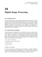
Figure 6.1(a) shows a typical holography set-up. Here the light beam from a laser is split
in two by means of a beamsplitter. One of the partial waves is directed onto the object by
a mirror and spread to illuminate the whole object by means of a microscope objective.
The object scatters the light in all directions, and some of it impinges onto the hologram
plate. This wave is called the object wave. The other partial wave is reflected directly
onto the hologram plate. This wave is called the reference wave. In the figure this wave
is collimated by means of a microscope objective and a lens. This is not essential, but it
is important that the reference wave constitutes a uniform illumination of the hologram
plate. The hologram plate must be a light-sensitive medium, e.g. a silver halide film plate
with high resolution. We now consider the mathematical description of this process in
more detail. For more comprehensive treatments, see Collier et al. (1971), Smith (1969),
Caulfield (1979) and Hariharan (1984).
Let the object and reference waves in the plane of the hologram be described by the
field amplitudes u
o
and u respectively. These two waves will interfere, resulting in an
intensity distribution in the hologram plane given by
I =|u + u
o
|
2
=|u|
2
+|u
o
|
2
+ u
∗
o
u + u
o
u
∗
(6.1)
Optical Metrology. Kjell J. G
˚
asvik
Copyright
2002 John Wiley & Sons, Ltd.
ISBN: 0-470-84300-4
148
HOLOGRAPHY
Laser
BS
M
MO
Lens
MO
M
Hologram
(a)
Object
Laser
BS
Virtual
object
−1st order
+1st order
0th order
H
MO
M
L
(b)
Figure 6.1 (a) Example of a holography set-up. BS = beamsplitter, M = mirrors, MO = micro-
scope objectives and (b) Reconstruction of the hologram
We now expose the film plate to this intensity distribution until it gets a suitable
blackening. Then it is removed from the plate holder and developed. We now have a
hologram. The process so far is called a hologram recording.
This hologram has an amplitude transmittance t which is proportional to the intensity
distribution given by Equation (6.1). This means that
t = αI = α|u|
2
+ α|u
o
|
2
+ αu
∗
o
+ αu
o
u
∗
= t
1
+ t
2
+ t
3
+ t
4
(6.2)
THE HOLOGRAPHIC PROCESS
149
We then replace the hologram back in the holder in the same position as in the record-
ing. We block the object wave and illuminate the hologram with the reference wave which
is now termed the reconstruction wave (see Figure 6.1(b)). The amplitude distribution u
a
just behind the hologram then becomes equal to the field amplitude of the reconstruction
wave multiplied by the amplitude transmittance of the hologram, i.e.
u
a
= t · u = α|u|
2
+|u
0
|
2
u + α(uu)u
∗
o
+ α|u|
2
u
o
(6.3)
As mentioned above, the reference (reconstruction) wave is a wave of uniform intensity.
The quantity |u|
2
is therefore a constant and the last term of Equation (6.3) thus becomes
(apart from a constant) identical to the original object wave u
o
. We therefore have been
able to reconstruct the object wave, maintaining its original phase and relative amplitude
distribution. The consequence is that, by looking through the hologram in the direction
of the object, we will observe the object in its three-dimensional nature even though the
physical object has been removed. Therefore this reconstructed wave is also called the
virtual wave.
The other two terms of Equation (6.3) represent waves propagating in the directions
indicated in Figure 6.1(b). In fact, a hologram can be regarded as a very complicated
grating where the first term of Equation (6.3) represents the zeroth order and the second
and third terms represent the ±first side orders diffracted from the hologram. If we could
use u
∗
, the conjugate of u, as the reconstruction wave, we see that the second term
of Equation (6.3) would have become proportional to |u|
2
u
∗
o
, i.e. the conjugate of the
object wave would have been reconstructed. The physical meaning of this deserves some
explanation. Complex conjugation of a field amplitude means changing the sign of its
phase. It thus gives a wave field returning back on its own path. u
∗
o
therefore represents a
wave propagating from the hologram back to the object forming an image of the object.
It is therefore termed the real wave. To reconstruct the hologram with u
∗
in the case of
a pure plane wave, the reconstruction wave can be reflected back through the hologram
by means of a plane mirror. An easier way, which also applies for a general reference
(reconstruction) wave, is to turn the hologram 180
◦
around the vertical axis. By placing
a screen in the real wave, we can observe the image of the object on the screen.
In Figure 6.2 another possible realization of a holography set-up is sketched. Here
the expanded laser beam is wavefront-divided by means of a mirror which reflects the
MO
Hologram
Laser
Mirror
Object
Figure 6.2
150
HOLOGRAPHY
reference wave onto the hologram. This set-up is normally more stable than in Figure 6.1
since fewer components are involved.
6.3 AN ALTERNATIVE DESCRIPTION
An alternative and more physical description of the holographic process has already been
touched on in Section 4.3.1. Let the point source P in Figure 4.7(a) represent the light
from a point on the object, and let the plane wave represent the reference wave. The
resulting zone plate pattern is recorded on a film. In Figure 4.7(b) this developed film
(the hologram) is illuminated by a plane wave (the reconstruction wave). When viewed
through the film, the diffracted, diverging spherical wave looks as if it is coming from
P. This argument can be repeated for all points on the object and give us the virtual
reconstructed object wave. The spherical wave converging to point P
represents the
real wave.
The circular zone plate is therefore also termed a unit hologram. In the general case
when the object- and reference waves are not normally incident on the hologram, the
pattern changes from circular to elliptical zone plate patterns, and the diffracted virtual
and real waves propagate in different directions in the reconstruction process.
6.4 UNCOLLIMATED REFERENCE
AND RECONSTRUCTION WAVES
We now consider in more detail the locations of the virtual and real images for the most
general recording and reconstructing geometries. To do this, it suffices to consider a single
object point source with coordinates (x
o
,y
o
,z
o
): see Figure 6.3. Here the hologram film
is placed in the xy-plane and the reference wave is coming from a point source with
coordinates (x
r
,y
r
,z
r
). Using quadratic (Fresnel) approximations to the spherical waves,
the object and reference fields of wavelength λ
1
incident on the xy-plane may be written
u
o
= U
o
exp
i
π
λ
1
z
o
[(x − x
o
)
2
+ (y − y
o
)
2
]
(6.4)
u = U exp
i
π
λ
1
z
r
[(x − x
r
)
2
+ (y − y
r
)
2
]
(6.5)
The transmittance of the resulting hologram we write as
t ∝|u
o
+ u|
2
= t
1
+ t
2
+ t
3
+ t
4
(6.6)
where the interesting terms (cf. Equation (6.2)) are
t
3
= αUU
o
exp
i
π
λ
1
z
r
[(x − x
r
)
2
+ (y − y
r
)
2
] − i
π
λ
1
z
o
[(x − x
o
)
2
+ (y − y
o
)
2
]
(6.7)
t
4
= αUU
o
exp
−i
π
λ
1
z
r
[(x − x
r
)
2
+ (y − y
r
)
2
] + i
π
λ
1
z
o
[(x − x
o
)
2
+ (y − y
o
)
2
]
(6.8)
UNCOLLIMATED REFERENCE AND RECONSTRUCTION WAVES
151
Reference source
(
x
r
,
y
r
,
z
r
)
Object
source
(
x
o
,
y
o
,
z
o
)
z
y
x
y
x
z
Reconstruction
source
(
x
p
,
y
p
,
z
p
)
Image
source
(
x
i
,
y
i
,
z
i
)
(a)
(b)
Figure 6.3 (a) Recording and (b) reconstruction geometries of point sources
In reconstruction, the hologram is illuminated by the spherical wave
u
p
= U
p
exp
i
π
λ
2
z
p
[(x − x
p
)
2
+ (y − y
p
)
2
]
(6.9)
where we have allowed for both a displaced (relative to the reference wave) point source
and a different wavelength λ
2
. The two reconstructed waves of interest are u
3
= t
3
u
p
and
u
4
= t
4
u
p
which gives (writing out the x-dependence only)
u
3
= t
3
u
p
∝ exp
i
π
λ
1
z
r
(x
2
+ x
2
r
− 2x
r
x) − i
π
λ
1
z
o
(x
2
+ x
2
o
− 2x
o
x) + i
π
λ
2
z
p
×(x
2
+ x
2
p
− 2x
p
x)
152
HOLOGRAPHY
= exp
iπ
x
2
r
λ
1
z
r
−
x
2
o
λ
1
z
o
+
x
2
p
λ
2
z
p
exp
iπ
1
λ
1
z
r
−
1
λ
1
z
o
+
1
λ
2
z
p
x
2
× exp
−2iπ
x
r
λ
1
z
r
−
x
o
λ
1
z
o
+
x
p
λ
2
z
p
x
(6.10)
By performing the same calculations for the wave u
4
, we get for the phase terms depending
on x
2
and x
u
4
∝ exp
iπ
−
1
λ
1
z
r
+
1
λ
1
z
o
+
1
λ
2
z
p
x
2
exp
−2iπ
−
x
r
λ
1
z
r
+
x
o
λ
1
z
o
+
x
p
λ
2
z
p
x
(6.11)
A spherical wave diverging from a point (x
i
,y
i
,z
i
) (writing out only the x-dependence)
is given as:
u
i
= U
i
exp
i
π
λ
2
z
i
(x − x
i
)
2
= U
i
exp
i
π
λ
2
z
i
(x
2
+ x
2
i
− 2x
i
x)
= U
i
exp
i
π
λ
2
z
i
x
2
i
exp
i
π
λ
2
z
i
x
2
exp
−2iπ
x
i
λ
2
z
i
x
(6.12)
By comparing this with the above expressions for u
3
and u
4
,weget
1
λ
2
z
i
=±
1
λ
1
z
r
∓
1
λ
1
z
o
+
1
λ
2
z
p
, i.e. z
i
=
1
z
p
±
λ
2
λ
1
z
r
∓
λ
2
λ
1
z
o
−1
(6.13)
and
x
i
λ
2
z
i
=±
x
r
λ
1
z
r
∓
x
o
λ
1
z
o
+
x
p
λ
2
z
p
, i.e. x
i
=∓
λ
2
z
i
λ
1
z
o
x
o
±
λ
2
z
i
λ
1
z
r
x
r
+
z
i
z
p
x
p
(6.14)
and with a completely analogous expression for y
i
:
y
i
=∓
λ
2
z
i
λ
1
z
o
y
o
±
λ
2
z
i
λ
1
z
r
y
r
+
z
i
z
p
y
p
(6.15)
Here the upper set of signs applies for u
3
, the real reconstructed wave, and the lower
set for u
4
, the virtual wave. What we have done is to find the coordinates (x
i
,y
i
,z
i
)
of the image point expressed by the coordinates of the object point, the source point of
the reference and the reconstruction waves. We see that when λ
2
= λ
1
and z
p
= z
r
,we
get for the virtual wave z
i
= z
o
. When, in addition, z
r
=∞ (collimated reference and
reconstruction waves), z
i
=−z
o
for the real wave.
From our calculations, we can associate a transversal magnification
m =
x
i
x
o
=
y
i
y
o
=
λ
2
z
i
λ
1
z
o
=
1 −
z
o
z
r
∓
λ
1
z
o
λ
2
z
p
−1
(6.16)
DIFFRACTION EFFICIENCY. THE PHASE HOLOGRAM
153
6.5 DIFFRACTION EFFICIENCY. THE PHASE
HOLOGRAM
Assume the object- and reference waves to be described by
u
o
= U
o
e
iφ
o
(6.17a)
and
u = U e
iφ
(6.17b)
respectively. The resulting amplitude transmittance then becomes
t = α[U
2
+ U
2
o
+ UU
o
e
i(φ−φ
o
)
+ UU
o
e
−i(φ−φ
o
)
]
= α(I + I
0
)[1 + V cos(φ − φ
0
)] (6.18)
which can be written as
t = t
b
1 +
V
2
e
i(φ−φ
o
)
+
V
2
e
−i(φ−φ
o
)
(6.19)
where I = U
2
, I
0
= U
2
0
and where we have introduced the visibility V (see eq. (3.29))
and the bias transmittance t
b
= α(I + I
o
). Since the transmittance t never can exceed
unity and 0 ≤ V ≤ 1, we see from Equation (6.18) that t
b
≤ 1/2.
The reconstructed object wave u
r
is found by multiplying the last term of
Equation (6.19) by the reconstruction wave u:
u
r
= t
b
V
2
Ue
iφ
o
(6.20)
and the intensity
I
r
=|u
r
|
2
=
1
4
U
2
t
2
b
V
2
(6.21)
The diffraction efficiency η of such a hologram we define as the ratio of the intensities
of the reconstructed wave and the reconstruction wave, i.e.
η = I
r
/I =
1
4
t
2
b
V
2
(6.22)
From this expression we see that the diffraction efficiency is proportional to the square
of the visibility. η therefore reaches its maximum when V = 1, i.e. when I
o
= I ,which
means that the diffraction efficiency is highest when the object and reference waves are
of equal intensity.
Maximum possible diffraction efficiency is obtained for V = 1andt
b
=
1
2
, which gives
η
max
=
1
16
= 6.25%
This type of hologram is called an amplitude hologram because its transmittance is a
pure amplitude variation. A hologram with a pure phase transmittance is called a phase
154
HOLOGRAPHY
hologram. Such holograms can be produced in different ways. A commonly applied
method consists of bleaching the exposed silver grains in the film emulsion of a standard
amplitude hologram. The recorded amplitude variation then changes to a corresponding
variation in emulsion thickness. The transmittance t
p
of a phase hologram formed by
bleaching of an amplitude hologram can be written as
t
p
= e
iM cos(φ
0
−φ)
=
∞
n=−∞
i
n
J
n
(M)e
in(φ
0
−φ)
(6.23)
where J
n
is the nth-order Bessel function. Here M is the amplitude of the phase delay.
From this expression we see that a sinusoidal phase grating will diffract light into n orders
in contrast to a sinusoidal amplitude grating which has only ±1st orders. The amplitude
of the first-order reconstructed object wave is found by multiplying Equation (6.23) by
the reconstruction wave u for n = 1, i.e.
u
r
= J
1
(M)U e
iφ
0
(6.24)
and the intensity
I
r
= U
2
J
2
1
(M) (6.25)
The diffraction efficiency becomes
η
p
= I
r
/I = J
2
1
(M) (6.26)
Since J
1max
(M) = 0.582 for M = 1.8, the maximum possible diffraction efficiency of a
phase hologram is
η
p,max
= 0.339 = 34%
6.6 VOLUME HOLOGRAMS
Up to now we have regarded the hologram film emulsion as having negligible thickness.
For emulsions of non-negligible thickness, however, volume effects, hitherto not con-
sidered, must be taken into account. For example, a thick phase hologram can reach a
theoretical diffraction efficiency of 100 per cent.
Consider Figure 6.4(a) where two plane waves are symmetrically incident at the angles
θ/2 to the normal on a thick emulsion. These waves will form interference planes parallel
to the yz-plane with spacings (cf. eq. (3.21)).
d =
λ
2sin(θ/2)
(6.27)
After development of this hologram, the exposed silver grains along these interference
planes will form silver layers that can be regarded as partially reflecting plane mirrors. In
Figure 6.4(b) this hologram is reconstructed with a plane wave incident at an angle ψ.
This wave will be reflected on each ‘mirror’ at an angle ψ.
VOLUME HOLOGRAMS
155
q/2
z
d
x
q/2
(a)
y
y
d
(b)
Figure 6.4
To obtain maximum intensity of the reflected, reconstructed wave, the path length
difference between light reflected from successive planes must be equal to λ.Fromthe
triangles in Figure 6.4(b) this gives
2d sin ψ = λ(6.28)
which, by substitution of Equation (6.27), gives
sin ψ = sin θ/2 (6.29)
i.e. the angles of incidence of the reconstruction and reference waves must be equal. It can
be shown that for a thick hologram, the intensity of the reconstructed wave will decrease
rapidly as ψ deviates from θ/2; see Section 13.6. This is referred to as the Bragg effect
and Equation (6.29) is termed the Bragg law.
156
HOLOGRAPHY
Emulsion Glass backing
Reference
Object
Single-colour
reflected light
‘White’
illumination
Virtual image
(a)
(b)
Figure 6.5
A special type of volume hologram, called a reflection hologram, is obtained by send-
ing the object and reference waves from opposite sides of the emulsion, as shown in
Figure 6.5(a). Then θ = 180
◦
and the stratified layers of metallic silver of the developed
hologram run nearly parallel to the surface of the emulsion with a spacing equal to λ/2
(see Equation (6.27)). Owing to the Bragg condition, the reconstruction wave must be
a duplication of the reference wave with the same wavelength, i.e. the hologram acts
as a colour filter in reflection. Therefore a reflection hologram can be reconstructed in
white light giving a reconstructed wave of the same wavelength as in the recording (see
Figure 6.5(b)). In practice the wavelength of the reflected light is shorter than that of the
exposing light, the reason being that the emulsion shrinks during the development process
and the silver layers become more closely spaced.
6.7 STABILITY REQUIREMENTS
In the description of the holographic recording process we assumed the spatial phases
of both the object- and reference waves to be time independent during exposure. It is
clear, however, that relative movements between the different optical components (like
mirrors, beamsplitters, the hologram, etc.) in the hologram set-up will introduce such phase