Windows Internals covering windows server 2008 and windows vista- P11
Bạn đang xem bản rút gọn của tài liệu. Xem và tải ngay bản đầy đủ của tài liệu tại đây (929.16 KB, 50 trang )
490
■ The Windows command prompt (%SystemRoot%\System32\Cmd.exe) enforces it for batch file
execution.
■ Windows Scripting Host components that start scripts—%SystemRoot%\System32\Cscript.exe
(for command-line scripts), %SystemRoot%\System32\Wscript.exe (for UI scripts), and
%SystemRoot%\System32\Scrobj.dll (for script objects)—enforce it for script execution.
Each of these components determines whether the restriction policies are enabled by reading the
registry value HKEY_LOCAL_MACHINE\Software\Microsoft\Policies\Windows\Safer
\CodeIdentifiers\TransparentEnabled, which if set to 1 indicates that policies are in effect. Then it
determines whether the code it’s about to execute matches one of the rules specified in a subkey of
the CodeIdentifiers key and, if so, whether or not the execution should be allowed. If there is no
match, the default policy, as specified in the DefaultLevel value of the CodeIdentifiers key,
determines whether the execution is allowed.
Software Restriction Policies are a powerful tool for preventing the unauthorized access of
code and scripts, but only if properly applied. Unless the default policy is set to disallow execution,
a user can make minor changes to an image that’s been marked as disallowed so that he can
bypass the rule and execute it. For example, a user can change an innocuous byte of a process
image so that a hash rule fails to recognize it, or copy a file to a different location to avoid a
path-based rule.
EXPERIMENT: Watching Software Restriction Policy enforcement
You can indirectly see Software Restriction Policies being enforced by watching accesses to
the registry when you attempt to execute an image that you’ve disallowed.
1. Run secpol.msc to open the Local Security Policy Editor, and navigate to the Software
Restriction Policies node.
2. Choose Create New Policies from the context menu if no policies are defined.
3. Create a path-based disallow restriction policy for %SystemRoot%\System32\Notepad.exe.
4. Run Process Monitor, and set an include filter for Safer. (See Chapter 4 for a description of
Process Monitor.)
5. Open a command prompt, and run Notepad from the prompt.
Your attempt to run Notepad should result in a message telling you that you cannot execute the
specified program, and Process Monitor should show the command prompt (cmd.exe) querying
the local machine restriction policies.
6.9 Conclusion
Windows provides an extensive array of security functions that meet the key requirements of
both government agencies and commercial installations. In this chapter, we’ve taken a brief tour
of the internal components that are the basis of these security features. In the next chapter, we’ll
look at the I/O system.
Please purchase PDF Split-Merge on www.verypdf.com to remove this watermark.
491
7. I/O System
The Windows I/O system consists of several executive components that together manage
hardware devices and provide interfaces to hardware devices for applications and the system. In
this chapter, we’ll first list the design goals of the I/O system, which have influenced its
implementation. We’ll then cover the components that make up the I/O system, including the I/O
manager, Plug and Play (PnP) manager, and power manager. Then we’ll examine the structure and
components of the I/O system and the various types of device drivers. We’ll look at the key data
structures that describe devices, device drivers, and I/O requests, after which we’ll describe the
steps necessary to complete I/O requests as they move through the system. Finally, we’ll present
the way device detection, driver installation, and power management work.
7.1 I/O System Components
The design goals for the Windows I/O system are to provide an abstraction of devices, both
hardware (physical) and software (virtual or logical), to applications with the following features:
■ Uniform security and naming across devices to protect shareable resources. (See Chapter 6 for a
description of the Windows security model.)
■ High-performance asynchronous packet-based I/O to allow for the implementation of scalable
applications.
■ Services that allow drivers to be written in a high-level language and easily ported between
different machine architectures.
■ Layering and extensibility to allow for the addition of drivers that transparently modify the
behavior of other drivers or devices, without requiring any changes to the driver whose behavior
or device is modified.
■ Dynamic loading and unloading of device drivers so that drivers can be loaded on-demand and
not consume system resources when unneeded.
■ Support for Plug and Play, where the system locates and installs drivers for newly detected
hardware, assigns them hardware resources they require, and also allows applications to discover
and activate device interfaces.
■ Support for power management so that the system or individual devices can enter low power
states.
■ Support for multiple installable file systems, including FAT, the CD-ROM file system (CDFS),
the Universal Disk Format (UDF) file system, and the Windows file system (NTFS). (See Chapter
11 for more specific information on file system types and architecture.)
Please purchase PDF Split-Merge on www.verypdf.com to remove this watermark.
492
■ Windows Management Instrumentation (WMI) support and diagnosability so that drivers can be
managed and monitored through WMI applications and scripts. (WMI is described in Chapter 4.)
To implement these features the Windows I/O system consists of several executive
components as well as device drivers, which are shown in Figure 7-1.
■ The I/O manager is the heart of the I/O system. It connects applications and system components
to virtual, logical, and physical devices, and it defines the infrastructure that supports device
drivers.
■ A device driver typically provides an I/O interface for a particular type of device. Device drivers
receive commands routed to them by the I/O manager that are directed at devices they manage,
and they inform the I/O manager when those commands complete. Device drivers often use the
I/O manager to forward I/O commands to other device drivers that share in the implementation of
a device’s interface or control.
■ The PnP manager works closely with the I/O manager and a type of device driver called a bus
driver to guide the allocation of hardware resources as well as to detect and respond to the arrival
and removal of hardware devices. The PnP manager and bus drivers are responsible for loading a
device’s driver when the device is detected. When a device is added to a system that doesn’t have
an appropriate device driver, the executive Plug and Play component calls on the device
installation services of a user-mode PnP manager.
■ The power manager also works closely with the I/O manager to guide the system, as well as
individual device drivers, through power-state transitions.
■ Windows Management Instrumentation support routines, called the Windows Driver Model
(WDM) WMI provider, allow device drivers to indirectly act as providers, using the WDM WMI
provider as an intermediary to communicate with the WMI service in user mode. (For more
information on WMI, see the section “Windows Management Instrumentation” in Chapter 4.)
■ The registry serves as a database that stores a description of basic hardware devices attached to
the system as well as driver initialization and configuration settings. (See the section “The
Registry” in Chapter 4 for more information.)
■ INF files, which are designated by the .inf extension, are driver installation files. INF files are
the link between a particular hardware device and the driver that assumes primary control of the
device. They are made up of scriptlike instructions describing the device they correspond to, the
source and target locations of driver files, required driver-installation registry modifications, and
driver dependency information. Digital signatures that Windows uses to verify that a driver file
has passed testing by the Microsoft Windows Hardware Quality Labs (WHQL) are stored in .cat
files.
■ The hardware abstraction layer (HAL) insulates drivers from the specifics of the processor and
interrupt controller by providing APIs that hide differences between platforms. In essence, the
Please purchase PDF Split-Merge on www.verypdf.com to remove this watermark.
493
HAL is the bus driver for all the devices on the computer’s motherboard that aren’t controlled by
other drivers.
The I/O Manager
The I/O manager is the core of the I/O system because it defines the orderly framework, or model,
within which I/O requests are delivered to device drivers. The I/O system is packet driven. Most
I/O requests are represented by an I/O request packet (IRP), which travels from one I/O system
component to another. (As you’ll discover in the section “Fast I/O,” fast I/O is the exception; it
doesn’t use IRPs.) The design allows an individual application thread to manage multiple I/O
requests concurrently. An IRP is a data structure that contains information completely describing
an I/O request. (You’ll find more information about IRPs in the section “I/O Request Packets.”)
The I/O manager creates an IRP that represents an I/O operation, passing a pointer to the IRP to
the correct driver and disposing of the packet when the I/O operation is complete. In contrast, a
driver receives an IRP, performs the operation the IRP specifies, and passes the IRP back to the
I/O manager, either for completion or to be passed on to another driver for further processing.
In addition to creating and disposing of IRPs, the I/O manager supplies code that is common to
different drivers and that the drivers call to carry out their I/O processing. By consolidating
common tasks in the I/O manager, individual drivers become simpler and more compact. For
example, the I/O manager provides a function that allows one driver to call other drivers. It also
manages buffers for I/O requests, provides timeout support for drivers, and records which
installable file systems are loaded into the operating system. There are close to a hundred different
routines in the I/O manager that can be called by device drivers.
Please purchase PDF Split-Merge on www.verypdf.com to remove this watermark.
494
The I/O manager also provides flexible I/O services that allow environment subsystems, such as
Windows and POSIX, to implement their respective I/O functions. These services include
sophisticated services for asynchronous I/O that allow developers to build scalable
highperformance server applications.
The uniform, modular interface that drivers present allows the I/O manager to call any driver
without requiring any special knowledge of its structure or internal details. The operating system
treats all I/O requests as if they were directed at a file; the driver converts the requests from
requests made to a virtual file to hardware-specific requests. Drivers can also call each other
(using the I/O manager) to achieve layered, independent processing of an I/O request.
Besides providing the normal open, close, read, and write functions, the Windows I/O system
provides several advanced features, such as asynchronous, direct, buffered, and scatter/gather I/O,
which are described in the “Types of I/O” section later in this chapter.
Typical I/O Processing
Most I/O operations don’t involve all the components of the I/O system. A typical I/O request
starts with an application executing an I/O-related function (for example, reading data from a
device) that is processed by the I/O manager, one or more device drivers, and the HAL.
As just mentioned, in Windows, threads perform I/O on virtual files. The operating system
abstracts all I/O requests as operations on a virtual file, hiding the fact that the target of an I/O
operation might not be a file-structured device. This abstraction generalizes an application’s
interface to devices. A virtual file refers to any source or destination for I/O that is treated as if it
were a file (such as files, directories, pipes, and mailslots). All data that is read or written is
regarded as a simple stream of bytes directed to these virtual files. User-mode applications
(whether Windows or POSIX) call documented functions, which in turn call internal I/O system
functions to read from a file, write to a file, and perform other operations. The I/O manager
dynamically directs these virtual file requests to the appropriate device driver. Figure 7-2
illustrates the basic structure of a typical I/O request flow.
Please purchase PDF Split-Merge on www.verypdf.com to remove this watermark.
495
In the following sections, we’ll be looking at these components more closely, covering the various
types of device drivers, how they are structured, how they load and initialize, and how they
process I/O requests. Then we’ll cover the operation and roles of the PnP manager and the power
manager.
7.2 Device Drivers
To integrate with the I/O manager and other I/O system components, a device driver must
conform to implementation guidelines specific to the type of device it manages and the role it
plays in managing the device. In this section, we’ll look at the types of device drivers Windows
supports as well as the internal structure of a device driver.
7.2.1 Types of Device Drivers
Windows supports a wide range of device driver types and programming environments. Even
within a type of device driver, programming environments can differ, depending on the specific
type of device for which a driver is intended. The broadest classification of a driver is whether it is
a user-mode or kernel-mode driver. Windows supports several types of usermode drivers:
■ Virtual device drivers (VDDs) are used to emulate 16-bit MS-DOS applications. They trap what
an MS-DOS application thinks are references to I/O ports and translate them into native Windows
I/O functions, which are then passed to the actual device driver. Because Windows is a fully
protected operating system, user-mode MS-DOS applications can’t access hardware directly and
thus must go through a real kernel-mode device driver. Because 64-bit editions of Windows do not
support 16-bit applications anymore, these types of drivers are not present on that architecture.
Please purchase PDF Split-Merge on www.verypdf.com to remove this watermark.
496
■ Windows subsystem printer drivers translate device-independent graphics requests to
printer-specific commands. These commands are then typically forwarded to a kernelmode port
driver such as the parallel port driver (Parport.sys) or the universal serial bus (USB) printer port
driver (Usbprint.sys).
■ User-Mode Driver Framework (UMDF) drivers are hardware device drivers that run in user
mode. They communicate to the kernel-mode UMDF support library through ALPC. See the
“User-Mode Driver Framework (UMDF)” section later in this chapter for more information. In
this chapter, the focus is on kernel-mode device drivers. There are many types of kernelmode
drivers, which can be divided into the following basic categories:
■ File system drivers accept I/O requests to files and satisfy the requests by issuing their own,
more explicit, requests to mass storage or network device drivers.
■ Plug and Play drivers work with hardware and integrate with the Windows power manager and
PnP manager. They include drivers for mass storage devices, video adapters, input devices, and
network adapters.
■ Non–Plug and Play drivers, which also include kernel extensions, are drivers or modules that
extend the functionality of the system. They do not integrate with the PnP or power managers
because they typically do not manage an actual piece of hardware. Examples include network API
and protocol drivers. Process Monitor’s driver, described in Chapter 4, is also an example.
Within the category of kernel-mode drivers are further classifications based on the driver model
that the driver adheres to and its role in servicing device requests.
WDM Drivers
WDM drivers are device drivers that adhere to the Windows Driver Model (WDM). WDM
includes support for Windows power management, Plug and Play, and WMI, and most Plug and
Play drivers adhere to WDM. There are three types of WDM drivers:
■ Bus drivers manage a logical or physical bus. Examples of buses include PCMCIA, PCI, USB,
IEEE 1394, and ISA. A bus driver is responsible for detecting and informing the PnP manager of
devices attached to the bus it controls as well as managing the power setting of the bus.
■ Function drivers manage a particular type of device. Bus drivers present devices to function
drivers via the PnP manager. The function driver is the driver that exports the operational interface
of the device to the operating system. In general, it’s the driver with the most knowledge about the
operation of the device.
■ Filter drivers logically layer above or below function drivers, augmenting or changing the
behavior of a device or another driver. For example, a keyboard capture utility could be
implemented with a keyboard filter driver that layers above the keyboard function driver.
Please purchase PDF Split-Merge on www.verypdf.com to remove this watermark.
497
In WDM, no one driver is responsible for controlling all aspects of a particular device. The bus
driver is responsible for detecting bus membership changes (device addition or removal), assisting
the PnP manager in enumerating the devices on the bus, accessing bus-specific configuration
registers, and, in some cases, controlling power to devices on the bus. The function driver is
generally the only driver that accesses the device’s hardware.
Layered Drivers
Support for an individual piece of hardware is often divided among several drivers, each providing
a part of the functionality required to make the device work properly. In addition to WDM bus
drivers, function drivers, and filter drivers, hardware support might be split between the following
components:
■ Class drivers implement the I/O processing for a particular class of devices, such as disk, tape,
or CD-ROM, where the hardware interfaces have been standardized, so one driver can serve
devices from a wide variety of manufacturers.
■ Port drivers implement the processing of an I/O request specific to a type of I/O port, such as
SCSI, and are implemented as kernel-mode libraries of functions rather than actual device drivers.
Port drivers are always written by Microsoft because the interfaces to write for are not
documented.
■ Miniport drivers map a generic I/O request to a type of port into an adapter type, such as a
specific SCSI adapter. Miniport drivers are actual device drivers that import the functions supplied
by a port driver. Miniport drivers are written by third parties, and they provide the interface for the
port driver.
An example will help demonstrate how device drivers work. A file system driver accepts a request
to write data to a certain location within a particular file. It translates the request into a request to
write a certain number of bytes to the disk at a particular “logical” location. It then passes this
request (via the I/O manager) to a simple disk driver. The disk driver, in turn, translates the
request into a physical location on the disk and communicates with the disk to write the data. This
layering is illustrated in Figure 7-3.
Please purchase PDF Split-Merge on www.verypdf.com to remove this watermark.
498
This figure illustrates the division of labor between two layered drivers. The I/O manager receives
a write request that is relative to the beginning of a particular file. The I/O manager passes the
request to the file system driver, which translates the write operation from a file-relative operation
to a starting location (a sector boundary on the disk) and a number of bytes to read. The file
system driver calls the I/O manager to pass the request to the disk driver, which translates the
request to a physical disk location and transfers the data.
Because all drivers—both device drivers and file system drivers—present the same framework to
the operating system, another driver can easily be inserted into the hierarchy without altering the
existing drivers or the I/O system. For example, several disks can be made to seem like a very
large single disk by adding a driver. This logical, volume manager driver is located between the
file system and the disk drivers, as shown in Figure 7-4. Volume manager drivers are described in
more detail in Chapter 8.
Please purchase PDF Split-Merge on www.verypdf.com to remove this watermark.
499
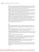
EXPERIMENT: Viewing the Loaded Driver List
You can see a list of registered drivers by executing the Msinfo32.exe utility from the Run dialog
box of the Start menu. Select the System Drivers entry under Software Environment to see the list
of drivers configured on the system. Those that are loaded have the text “Yes” in the Started
column, as shown here:
Please purchase PDF Split-Merge on www.verypdf.com to remove this watermark.
500
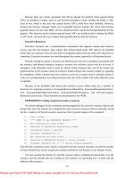
You can also view the list of loaded kernel-mode drivers with Process Explorer from Windows
Sysinternals (www.microsoft.com/technet/sysinternals
.) Run Process Explorer, select the System
process, and select DLLs from the Lower Pane menu entry in the View menu. Process Explorer
lists the loaded drivers, their names, version information (including company and description), and
load address (assuming you have configured Process Explorer to display the corresponding
columns):
Finally, if you’re looking at a crash dump (or live system) with the kernel debugger, you can get a
similar display with the kernel debugger lm kv command:
1. lkd> lm kv
2. start end module name
3. 82007000 823c0000 nt (pdb symbols)
4. c:\programming\symbols\ntkrpamp.pdb\37D328E3BAE5460F8E662756ED80951D2
\ntkrpamp.pdb
5. Loaded symbol image file: ntkrpamp.exe
6. Image path: ntkrpamp.exe
7. Image name: ntkrpamp.exe
8. Timestamp: Fri Jan 18 21:30:58 2008 (47918B12)
9. CheckSum: 00372038
10. ImageSize: 003B9000
11. File version: 6.0.6001.18000
12. Product version: 6.0.6001.18000
13. File flags: 0 (Mask 3F)
14. File OS: 40004 NT Win32
15. File type: 1.0 App
16. File date: 00000000.00000000
17. Translations: 0409.04b0
18. CompanyName: Microsoft Corporation
19. ProductName: Microsoft® Windows® Operating System
Please purchase PDF Split-Merge on www.verypdf.com to remove this watermark.
501
20. InternalName: ntkrpamp.exe
21. OriginalFilename: ntkrpamp.exe
22. ProductVersion: 6.0.6001.18000
23. FileVersion: 6.0.6001.18000 (longhorn_rtm.080118-1840)
24. FileDescription: NT Kernel & System
25. LegalCopyright: © Microsoft Corporation. All rights reserved.
26. 823c0000 823f3000 hal (deferred)
27. Image path: halmacpi.dll
28. Image name: halmacpi.dll
29. Timestamp: Fri Jan 18 21:27:20 2008 (47918A38)
30. CheckSum: 0003859F
31. ImageSize: 00033000
32. Translations: 0000.04b0 0000.04e0 0409.04b0 0409.04e0
33. 82600000 82671000 ksecdd (deferred)
34. Image path: \SystemRoot\System32\Drivers\ksecdd.sys
35. Image name: ksecdd.sys
36. Timestamp: Fri Jan 18 21:41:20 2008 (47918D80)
37. CheckSum: 0006E742
38. ImageSize: 00071000
39. Translations: 0000.04b0 0000.04e0 0409.04b0 0409.04e0
7.2.2 Structure of a Driver
The I/O system drives the execution of device drivers. Device drivers consist of a set of routines
that are called to process the various stages of an I/O request. Figure 7-5 illustrates the key
driver-function routines.
■ An initialization routine The I/O manager executes a driver’s initialization routine, which is
typically named DriverEntry, when it loads the driver into the operating system. The routine fills
in system data structures to register the rest of the driver’s routines with the I/O manager and
performs any global driver initialization that’s necessary.
Please purchase PDF Split-Merge on www.verypdf.com to remove this watermark.
502
■ An add-device routine A driver that supports Plug and Play implements an adddevice routine.
The PnP manager sends a driver notification via this routine whenever a device for which the
driver is responsible is detected. In this routine, a driver typically allocates a device object
(described later in this chapter) to represent the device.
■ A set of dispatch routines Dispatch routines are the main functions that a device driver provides.
Some examples are open, close, read, and write and any other capabilities the device, file system,
or network supports. When called on to perform an I/O operation, the I/O manager generates an
IRP and calls a driver through one of the driver’s dispatch routines.
■ A start I/O routine A driver can use a start I/O routine to initiate a data transfer to or from a
device. This routine is defined only in drivers that rely on the I/O manager to queue their incoming
I/O requests. The I/O manager serializes IRPs for a driver by ensuring that the driver processes
only one IRP at a time. Most drivers process multiple IRPs concurrently, but serialization makes
sense for some drivers, such as a keyboard driver.
■ An interrupt service routine (ISR) When a device interrupts, the kernel’s interrupt dispatcher
transfers control to this routine. In the Windows I/O model, ISRs run at device interrupt request
level (DIRQL), so they perform as little work as possible to avoid blocking lower-level interrupts
unnecessarily. (See Chapter 3 for more information on IRQLs.) An ISR usually queues a deferred
procedure call (DPC), which runs at a lower IRQL (DPC/dispatch level), to execute the remainder
of interrupt processing. (Only drivers for interrupt-driven devices have ISRs; a file system driver,
for example, doesn’t have one.)
■ An interrupt-servicing DPC routine A DPC routine performs most of the work involved in
handling a device interrupt after the ISR executes. The DPC routine executes at a lower IRQL
(DPC/dispatch level) than that of the ISR, which runs at device level, to avoid blocking other
interrupts unnecessarily. A DPC routine initiates I/O completion and starts the next queued I/O
operation on a device. Although the following routines aren’t shown in Figure 7-5, they’re found
in many types of device drivers:
■ One or more I/O completion routines A layered driver might have I/O completion routines that
will notify it when a lower-level driver finishes processing an IRP. For example, the I/O manager
calls a file system driver’s I/O completion routine after a device driver finishes transferring data to
or from a file. The completion routine notifies the file system driver about the operation’s success,
failure, or cancellation, and it allows the file system driver to perform cleanup operations.
■ A cancel I/O routine If an I/O operation can be canceled, a driver can define one or more cancel
I/O routines. When the driver receives an IRP for an I/O request that can be canceled, it assigns a
cancel routine to the IRP. If a thread that issues an I/O request exits before the request is
completed or cancels the operation (with the CancelIo Windows function, for example), the I/O
manager executes the IRP’s cancel routine if one is assigned to it. A cancel routine is responsible
for performing whatever steps are necessary to release any resources acquired during the
processing that has already taken place for the IRP as well as completing the IRP with a canceled
status.
Please purchase PDF Split-Merge on www.verypdf.com to remove this watermark.
503
■ Fast dispatch routines Drivers that make use of the cache manager in Windows (see Chapter 10
for more information on the cache manager), such as file system drivers, typically provide these
routines to allow the kernel to bypass typical I/O processing when accessing the driver. For
example, operations such as reading or writing can be quickly performed by accessing the cached
data directly, instead of taking the I/O manager’s usual path that generates discrete I/O operations.
Fast dispatch routines are also used as a mechanism for callbacks from the memory manager and
cache manager to file system drivers. For instance, when creating a section, the memory manager
calls back into the file system driver to acquire the file exclusively.
■ An unload routine An unload routine releases any system resources a driver is using so that the
I/O manager can remove them from memory. Any resources acquired in the initialization routine
are usually released in the unload routine. A driver can be loaded and unloaded while the system is
running if the driver supports it, but the unload routine will be called only after all file handles to
the device are closed.
■ A system shutdown notification routine This routine allows driver cleanup on system shutdown.
■ Error-logging routines When unexpected errors occur (for example, when a disk block goes
bad), a driver’s error-logging routines note the occurrence and notify the I/O manager. The I/O
manager writes this information to an error log file.
Note Most kernel-mode device drivers are written in C. Some drivers are written in C++, but
there’s no specific support for C++ in the Windows Driver Kit (WDK). Use of assembly language
is highly discouraged because of the complexity it introduces and its effect of making a driver
difficult to port between hardware architectures such as the x86, x64, and IA64.
7.2.3 Driver Objects and Device Objects
When a thread opens a handle to a file object (described in the “I/O Processing” section later in
this chapter), the I/O manager must determine from the file object’s name which driver (or drivers)
it should call to process the request. Furthermore, the I/O manager must be able to locate this
information the next time a thread uses the same file handle. The following system objects fill this
need:
■ A driver object represents an individual driver in the system. The I/O manager obtains the
address of each of the driver’s dispatch routines (entry points) from the driver object.
■ A device object represents a physical or logical device on the system and describes its
characteristics, such as the alignment it requires for buffers and the location of its device queue to
hold incoming IRPs.
The I/O manager creates a driver object when a driver is loaded into the system, and it then calls
the driver’s initialization routine (for example, DriverEntry), which fills in the object attributes
with the driver’s entry points.
Please purchase PDF Split-Merge on www.verypdf.com to remove this watermark.
504
After loading, a driver can create device objects to represent devices, or even an interface to the
driver, at any time by calling IoCreateDevice or IoCreateDeviceSecure. However, most Plug and
Play drivers create devices with their add-device routine when the PnP manager informs them of
the presence of a device for them to manage. Non–Plug and Play drivers, on the other hand,
usually create device objects when the I/O manager invokes their initialization routine. The I/O
manager unloads a driver when its last device object has been deleted and no references to the
driver remain.
When a driver creates a device object, the driver can optionally assign the device a name. A name
places the device object in the object manager namespace, and a driver can either explicitly define
a name or let the I/O manager autogenerate one. (The object manager namespace is described in
Chapter 3.) By convention, device objects are placed in the \Device directory in the namespace,
which is inaccessible by applications using the Windows API.
Note Some drivers place device objects in directories other than \Device. For example, the IDE
driver creates the device objects that represent IDE ports and channels in the \Device\Ide directory.
See Chapter 8 for a description of storage architecture, including the way storage drivers use
device objects.
If a driver needs to make it possible for applications to open the device object, it must create a
symbolic link in the \Global?? directory to the device object’s name in the \Device directory. (See
Chapter 3 for more information on \??.) Non–Plug and Play and file system drivers typically
create a symbolic link with a well-known name (for example, \Device\Hardware2). Because
well-known names don’t work well in an environment in which hardware appears and disappears
dynamically, PnP drivers expose one or more interfaces by calling the IoRegisterDeviceInterface
function, specifying a GUID (globally unique identifier) that represents the type of functionality
exposed. GUIDs are 128-bit values that you can generate by using a tool called Guidgen that is
included with the WDK and the Windows SDK. Given the range of values that 128 bits represents,
it’s statistically almost certain that each GUID that Guidgen creates will be forever and globally
unique.
IoRegisterDeviceInterface determines the symbolic link that is associated with a device instance;
however, a driver must call IoSetDeviceInterfaceState to enable the interface to the device before
the I/O manager actually creates the link. Drivers usually do this when the PnP manager starts the
device by sending the driver a start-device command.
An application wanting to open a device object represented with a GUID can call Plug and
Play setup functions in user space, such as SetupDiEnumDeviceInterfaces, to enumerate the
interfaces present for a particular GUID and to obtain the names of the symbolic links it can use to
open the device objects. For each device reported by SetupDiEnumDeviceInterfaces, an
application executes SetupDiGetDeviceInterfaceDetail to obtain additional information about the
device, such as its autogenerated name. After obtaining a device’s name from SetupDiGetDevice-
InterfaceDetail, the application can execute the Windows function CreateFile to open the device
and obtain a handle.
Please purchase PDF Split-Merge on www.verypdf.com to remove this watermark.
505
EXPERIMENT: Looking at the \Device Directory
You can use the WinObj tool from Sysinternals or the !object kernel debugger command to view
the device names under \Device in the object manager namespace. The following screen shot
shows an I/O manager–assigned symbolic link that points to a device object in \Device with an
autogenerated name:
When you run the !object kernel debugger command and specify the \Device directory, you
should see output similar to the following:
1. lkd> !object \Device
2. Object: 8b611b88 Type: (84d10d40) Directory
3. ObjectHeader: 8b611b70 (old version)
4. HandleCount: 0 PointerCount: 365
5. Directory Object: 8b602470 Name: Device
6. Hash Address Type Name
7. ---- ------- ---- ----
8. 00 85557a00 Device KsecDD
9. 855589d8 Device Ndis
10. 8b6151b0 SymbolicLink {941D252A-0BDA-4772-B3CB-30697579BD4A}
11. 86859030 Device 0000009b
12. 88c92da8 Device SrvNet
13. 886723f0 Device Beep
14. 8b71fb90 SymbolicLink ScsiPort2
15. 84d17a98 Device 00000032
16. 84d15f00 Device 00000025
17. 84d13030 Device 00000019
18. 01 86d44030 Device NDMP10
19. 8d291eb0 SymbolicLink {E85EEE75-32E3-4A94-8905-52709C2C9BCC}
20. 886da3c8 Device Netbios
21. 86862030 Device 0000009c
22. 84d177c8 Device 00000033
23. 84d15c70 Device 00000026
24. 02 86de9030 Device NDMP11
Please purchase PDF Split-Merge on www.verypdf.com to remove this watermark.
506
25. 84d19320 Device 00000040
26. 88633ca0 Device NetBT_Tcpip_{033C65A4-C1D6-4824-B420-DDAEADFF873E}
27. 8b7dcdd0 SymbolicLink Ip
28. 84d17500 Device 00000034
29. 84d159a8 Device 00000027
30. 03 86df3380 Device NDMP12
31. 8515ede0 Device WMIAdminDevice
32. 84d1a030 Device 00000041
33. 8862e040 Device Video0
34. 86eaec28 Device KeyboardClass0
35. 84d03b00 Device KMDF0
36. 84d17230 Device 00000035
37. 84d156e0 Device 00000028
38. 04 86e0d030 Device NDMP13
39. 86e65030 Device NDMP20
40. 85541030 Device VolMgrControl
41. 86e6c358 Device Tun0
42. 84d1ad68 Device 00000042
43. 8862ec48 Device Video1
44. 88e15158 Device 0000009f
45. 9badd848 SymbolicLink MailslotRedirector
46. 86e1d488 Device KeyboardClass1
47. §
When you execute !object and specify an object manager directory object, the kernel debugger
dumps the contents of the directory according to the way the object manager organizes it
internally. For fast lookups, a directory stores objects in a hash table based on a hash of the object
names, so the output shows the objects stored in each bucket of the directory’s hash table.
As Figure 7-6 illustrates, a device object points back to its driver object, which is how the I/O
manager knows which driver routine to call when it receives an I/O request. It uses the device
object to find the driver object representing the driver that services the device. It then indexes into
the driver object by using the function code supplied in the original request; each function code
corresponds to a driver entry point. (The function codes shown in Figure 7-6 are described in the
section “IRP Stack Locations” later in this chapter.)
A driver object often has multiple device objects associated with it. The list of device objects
represents the physical and logical devices that the driver controls. For example, each partition of
a hard disk has a separate device object that contains partition-specific information. However, the
same hard disk driver is used to access all partitions. When a driver is unloaded from the system,
the I/O manager uses the queue of device objects to determine which devices will be affected by
the removal of the driver.
Please purchase PDF Split-Merge on www.verypdf.com to remove this watermark.
507
EXPERIMENT: Displaying Driver and Device Objects
You can display driver and device objects with the kernel debugger !drvobj and !devobj
commands, respectively. In the following example, the driver object for the keyboard class driver
is examined, and its lone device object viewed:
1. lkd> !drvobj kbdclass
2. Driver object (86e379a0) is for:
3. \Driver\kbdclass
4. Driver Extension List: (id , addr)
5. Device Object list:
6. 86e1d488 86eaec28
7. lkd> !devobj 86eaec28
8. Device object (86eaec28) is for:
9. KeyboardClass0 \Driver\kbdclass DriverObject 86e379a0
10. Current Irp 00000000 RefCount 0 Type 0000000b Flags 00002044
11. DevExt 86eaece0 DevObjExt 86eaedc0
12. ExtensionFlags (0x00000800)
13. Unknown flags 0x00000800
14. AttachedDevice (Upper) 86e15a40 \Driver\ctrl2cap
15. AttachedTo (Lower) 86e15020 \Driver\i8042prt
16. Device queue is not busy
Notice that the !devobj command also shows you the addresses and names of any device objects
that the object you’re viewing is layered over (the AttachedTo line) as well as the device objects
layered on top of the object specified (the AttachedDevice line). Using objects to record
information about drivers means that the I/O manager doesn’t need to know details about
individual drivers. The I/O manager merely follows a pointer to locate a driver, thereby providing
a layer of portability and allowing new drivers to be loaded easily. Representing devices and
Please purchase PDF Split-Merge on www.verypdf.com to remove this watermark.
508
drivers with different objects also makes it easy for the I/O system to assign drivers to control
additional or different devices if the system configuration changes.
7.2.4 Opening Devices
File objects are the kernel-mode constructs for handles to files or devices. File objects clearly fit
the criteria for objects in Windows: they are system resources that two or more user-mode
processes can share, they can have names, they are protected by object-based security, and they
support synchronization. Although most shared resources in Windows are memorybased resources,
most of those that the I/O system manages are located on physical devices or represent actual
physical devices. Despite this difference, shared resources in the I/O system, like those in other
components of the Windows executive, are manipulated as objects. (See Chapter 3 for a
description of the object manager and Chapter 6 for information on object security.)
File objects provide a memory-based representation of resources that conform to an I/Ocentric
interface, in which they can be read from or written to. Table 7-1 lists some of the file object’s
attributes. For specific field declarations and sizes, see the structure definition for FILE_OBJECT
in Ntddk.h.
Please purchase PDF Split-Merge on www.verypdf.com to remove this watermark.
509
In order to maintain some level of opacity toward non-kernel code that uses the file object, as well
as to enable extending the file object functionality without enlarging the structure, the file object
also contains an extension field, which allows for up to six different kinds of additional parameters.
These are described in Table 7-2.
EXPERIMENT: Viewing the File Object Data Structure
You can view the contents of the kernel-mode file object data structure with the kernel debugger’s
dt command:
1. lkd> dt nt!_FILE_OBJECT
2. +0x000 Type : Int2B
3. +0x002 Size : Int2B
4. +0x004 DeviceObject : Ptr32 _DEVICE_OBJECT
5. +0x008 Vpb : Ptr32 _VPB
6. +0x00c FsContext : Ptr32 Void
7. +0x010 FsContext2 : Ptr32 Void
8. +0x014 SectionObjectPointer : Ptr32 _SECTION_OBJECT_POINTERS
9. +0x018 PrivateCacheMap : Ptr32 Void
10. +0x01c FinalStatus : Int4B
11. +0x020 RelatedFileObject : Ptr32 _FILE_OBJECT
12. +0x024 LockOperation : UChar
13. +0x025 DeletePending : UChar
14. +0x026 ReadAccess : UChar
15. +0x027 WriteAccess : UChar
16. +0x028 DeleteAccess : UChar
17. +0x029 SharedRead : UChar
Please purchase PDF Split-Merge on www.verypdf.com to remove this watermark.