Numerical analysis of externally prestressed concrete beams part 2
Bạn đang xem bản rút gọn của tài liệu. Xem và tải ngay bản đầy đủ của tài liệu tại đây (2.04 MB, 34 trang )
-95-
Chapter 5
PARAMETRIC STUDY
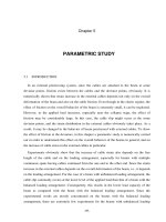
5.1 INTRODUCTION
In an external prestressing system, since the cables are attached to the beam at some
deviator points, friction exists between the cables and the deviator points, obviously. It is
numerically shown that strain increase in the external cables depends not only on the overall
deformation of the beam and also on the cable friction. Even though in the elastic regime, the
effect of friction on the overall behavior of the beam is extremely small, it can be neglected.
However, as the applied load increases, especially near the collapse stage, the effect of
friction may be considerably large. In this case, the cable slip might occur at the some
deviator points, and the strain distribution in the external cables obviously takes place. As a
result, it may be changed in the behavior of beam prestressed with external cables. To show
the effect of friction at the deviators, in this chapter a parametric study is numerically carried
out in order to understand this effect on the overall behavior of the beams in general, and on
the increase of cable stress in the external cables in particular.
Experiments obviously show that the increase of cable strain also depends on the free
length of the cable and on the loading arrangement, especially for beams with multiple
continuous spans having cables continued from the one end to the other end. Since the strain
increase in the external cables depends on the overall deformation of the beam, i.e., it depends
on the loading arrangement. For the case of a beam with unbalanced loading arrangement, the
cable slip commonly occurs at the lower level of the applied load than that of a beam with the
balanced loading arrangement. Consequently, this results in the lower load capacity of the
beam as compared with the beam with the balanced loading arrangement. Since the
experimental works are mostly concentrated on the beams with the balanced loading
arrangement, there are extremely few experiments for the beams with unbalanced loading
96
-96-
arrangement. For two span continuous beams with the external load applied only on one span,
the defection of unloaded span has usually upward deflection, resulting caused the adverse
effect on the strain increase in the external cables. The effect of unbalanced loading
arrangement for multiple span continuous beams was also indicated by experiments, which
have been recently reported elsewhere
20, 60, 74)
. In order to better understanding this
phenomenon, a parametric study on the effect of loading arrangement is also carried out in
this chapter. The parametric evaluation is presented in the next section.
5.2 PARAMETRIC EVALUATION
In this chapter, a parametric study is performed for beams prestressed with external cables
with two purposes: 1) to investigate the friction effect at the deviator points on the behavior of
simply supported beam; 2) to investigate the effect of loading arrangement on the behavior of
two span continuous beam with external cables continued from one end to the other end in
order to examine the stress increase in the external cables under the unbalanced loading
condition. The predicted results are then discussed with emphasis on the effects of friction at
the deviators and the loading arrangement on both the load-deflection and the load-increase of
cable stress relationships.
5.2.1 Effect of friction at deviators
The effect of friction is performed on a simply supported beam with a box section, which
was tested at the Research Center for Experiments and Studies on Construction and Public
Fig.5.1 Layout scheme of beam tested by CEBTP
1000
400
400 100
100
100100
3000 15001500
480
1000
400
400 100
100
100100
3000 15001500
480
-97-
Work (CEBTP) in France
71, 75)
. The dimensions of the beam, span length and loading
arrangement are shown in Fig.5.1, and material properties are shown in Table 5.1. Two
deviators were provided at the distance of 3.0 m from each other, and symmetrically located
from the midspan section. The beam is analyzed by considering four different cases: 1) free
slip; 2) slip with friction; 3) partially fixed; and 4) perfectly fixed. For the case of cables being
free slip, the friction coefficient is equal to zero, whereas for the case of cables being slip with
friction as usually seen in the nature, the friction coefficient is assumed to be equal to 0.17.
While for the case of cables being perfectly fixed, the friction coefficient should have a value,
which is big enough to restrain any movement at the deviators. In this case the value of
friction coefficient referred to is from Garcia-Vargas’s model
71)
, which was assumed to be
equal to 2.0. For the case of partially fixed, the friction coefficient is assumed to be 1.0, which
has an intermediate value between the cases of slip with friction and perfectly fixed in order
to examine the extent of fixity at the deviators.
Fig.5.2 plots the predicted characteristics of the load-deflection response for four cases and
also the results obtained from the experimental observations. It can be seen from this figure
that the deflection responses behave essentially in the same manner as in the experimental
observations until the decompression stage regardless of friction. This is because the beam
a) Entire responses b) Responses after the decompression
Fig.5.2 Effect of friction at the deviators on the load-deflection responses
Table 5.1 Material properties (MPa)
Concrete Prestressing cable
f’
c
E
c
f
py
f
pu
E
ps
41.0 3.8x10
4
1570 1860 1.95x10
5
0 0.02 0.04 0.06 0.08
400
450
500
550
600
650
Applied load [kN]
Displacement [m]
Exp. results
Free slip
Slip with friction
Partially fixed
Perfectly fixed
0 0.02 0.04 0.06 0.08
400
450
500
550
600
650
Applied load [kN]
Displacement [m]
Exp. results
Free slip
Slip with friction
Partially fixed
Perfectly fixed
Exp. results
Free slip
Slip with friction
Partially fixed
Perfectly fixed
0 0.02 0.04 0.06 0.08
0
100
200
300
400
500
600
700
Applied load [kN]
Displacement [m]
Exp. results
Free slip
Slip with friction
Partially fixed
Perfectly fixed
0 0.02 0.04 0.06 0.08
0
100
200
300
400
500
600
700
Applied load [kN]
Displacement [m]
Exp. results
Free slip
Slip with friction
Partially fixed
Perfectly fixed
Exp. results
Free slip
Slip with friction
Partially fixed
Perfectly fixed
98
-98-
deflection is very small, which induces a small tensile force in each cable segment, leading to
an extremely small unbalanced force at a deviator. As a result, the cable slip cannot occur at
this stage, generally. That is the friction at the deviators does have an insignificant effect on
the deflection response until the decompression stage. After the decompression, the deflection
responses of beam with consideration of free slip and slip with friction are more or less
identical to the experimental results, whereas for the case of perfectly fixed, the prediction
overestimates the strength of the beam at ultimate. The reason for this can be explained that
since the cables are assumed to be a perfectly fixed at the deviators, the stress increase in each
segment is independent from that of the others. As the applied load increases, the deflection of
midspan and the accompanying concrete strain at the cable level between the deviator points
becomes large, resulting in a great increase of cable stress of middle segment (see Fig.5.3). A
greater stress variation in the middle segment of a cable induces a higher load carrying
capacity, resulting in the overestimating prediction of ultimate strength of the beam.
a) Entire responses b) Responses after the decompression
Fig 5.3 Effect of friction at the deviators on the load-increase of cable stress
Fig.5.4 Increase of cable stress vs. deflection
0 300 600 900 1200 1500
0
100
200
300
400
500
600
700
Increase of cable stress [N/mm
2
]
Applied load [kN]
Exp. results
Free slip
Slip with friction
Partially fixed
Perfectly fixed
0 300 600 900 1200 1500
0
100
200
300
400
500
600
700
Increase of cable stress [N/mm
2
]
Applied load [kN]
Exp. results
Free slip
Slip with friction
Partially fixed
Perfectly fixed
Exp. results
Free slip
Slip with friction
Partially fixed
Perfectly fixed
0 300 600 900 1200 1500
400
450
500
550
600
650
Increase of cable stress [N/mm
2
]
Applied load [kN]
Exp. results
Free slip
Slip with friction
Partially fixed
Perfectly fixed
0 300 600 900 1200 1500
400
450
500
550
600
650
Increase of cable stress [N/mm
2
]
Applied load [kN]
Exp. results
Free slip
Slip with friction
Partially fixed
Perfectly fixed
Exp. results
Free slip
Slip with friction
Partially fixed
Perfectly fixed
0 0.02 0.04 0.06 0.08
0
300
600
900
1200
1500
Displacement [m]
Increase of cable stress [N/mm
2
]
Slip with friction
Partially fixed
Perfectly fixed
Exp. results
Free slip
0 0.02 0.04 0.06 0.08
0
300
600
900
1200
1500
Displacement [m]
Increase of cable stress [N/mm
2
]
Slip with friction
Partially fixed
Perfectly fixed
Exp. results
Free slip
-99-
Fig.5.3 presents the results of stress increase in the external cables. It is apparently seen
that the increase of cable stress exceeds the yielding strength for the cases of partially fixed
and perfectly fixed, and remains in the elastic range for the cases of free slip and slip with
friction. Although a small discrepancy has been observed in the predicted results for the cases
with free slip and slip with friction, the same rate of stress increase, however, is
approximately found until the ultimate state, and very similar to the experimental
observations.
A fairly linear relationship between the increase of cable stress and the beam deflection is
also observed as shown in Fig.5.4. This indicates that the stress increase in a cable is almost
proportional to the midspan deflection until the crushing strain reaches
in the concrete.
However, the rate of stress increase in the case of cable being perfectly fixed is quite different
from the other cases. It is also seen from this figure that the rate of stress increase is reduced
from the deflection of 40.0 mm as observed in the experiment. This is because the rate of
stress increase in the external cables is smaller than the rate of increase in the beam deflection
as the applied load increases from this point. However, the rate of stress increase observed by
the predictions does not change except the case of cable being slip with friction. This may be
indicated in the calculated results for the ultimate load capacity, which are a little higher than
that of the experimental observations (see Table 5.2). It is also found from the results of the
case of slip with friction that the concrete strain at the critical section suddenly jumps as the
applied load reaches the peak load. As the crushing strain reaches in the concrete at the
compression region, the applied load is sharply reduced, accompanying the beam deflection
increases significantly as shown in Fig.5.2. This causes the change in the rate of stress
increase as shown in the curve of the increase of cable stress vs. deflection. Because the
Fig.5.5 Comparison between the cases of partially fixed
and perfectly fixed
0 0.02 0.04 0.06 0.08
0
300
600
900
1200
1500
Displacement [m]
Increase of cable stress [N/mm
2
]
Midspan
segment
End
segment
Exp. results
Partially fixed
Perfectly fixed
0 0.02 0.04 0.06 0.08
0
300
600
900
1200
1500
Displacement [m]
Increase of cable stress [N/mm
2
]
Midspan
segment
End
segment
Exp. results
Partially fixed
Perfectly fixed
100
-100-
deflection of the beam increases noticeably after the crushing of concrete, the linear
relationship, therefore, is terminated as shown obviously for the case of slip with friction.
Fig.5.5 shows a comparison between the cases of perfectly fixed and partially fixed in
terms of the increase of cable stress vs. deflection responses. It can be seen from this figure
that since the external cables are being perfectly fixed at the deviators as in the case of
perfectly fixed, the stress increase in the midspan segment and the end segment is totally
different. While for the case of the cables being partially fixed at the deviators, the difference
of the stress increase in the midspan segment and the end segment is lesser as compared to the
case of perfectly fixed. This indicates that some cable slip might occur at the deviator points,
resulting in transfer of cable stress from the midspan segment to the end segment. This
phenomenon is agreed well with the experimental observations, which have been conducted
by Fujioka, A., et al.
76)
It is also found from the predicted results that the ultimate load of the beam with
consideration of partially fixed at the deviators does not increase much as compared to the
cases of free slip and slip with friction (see Fig.5.2 and Table 5.2). However, the stress
increase in the external cables is much higher as the comparison has been made. This is
because the strain variation in the external cables depends not only on the overall deformation
of the beam, but also on the free length of a cable between two successive deviators, i.e., it
depends on a ratio of L
d
/L (the distance between the deviators per the total span length). For
the beam tested by CEBTP, this ratio of L
d
/L is equal to 0.5, which seems to be considerably
large. In this case the extent of fixity of cable at the deviators has significant effects on the
stress increase in the external cables rather than on the load-deflection response of the beam.
It is believed that when the ratio of L
d
/L is rather small, both the ultimate strength and the
stress increase in the cables are significantly increased due to the extent of fixity of cable at
Table 5.2. Comparison between the experimental observations
and the calculated results
Case of study
Ultimate
load
kN
Ultimate
deflection
mm
Increase of
cable stress
MPa
Free slip
Slip with friction
Partially fixed
Perfectly fixed
Exp. observations
586.2
580.6
594.0
589.9
570.0
58.1
54.0
58.0
45.4
53.0
741.7
679.4
995.5
1455.0
745.0
-101-
the deviators. The improvement due to the fixity of cable was also verified by the
experimental observations for two pairs of beams with the different ratio of L
d
/L, which have
been reported elsewhere
76)
.
The results at the ultimate stage for the beams under the different bondage of cable at the
deviators are presented in Table 5.2. It should be, generally, noted that friction at the deviators
reduces the ultimate deflection and increases the stress in the prestressing cables. However, it
is found from the analysis that the results of the case of slip with friction show somewhat
contrary to the other cases. The reason for that might be the strain-jump, which is happened in
the concrete at the critical section as explained early. Note that the predicted results in terms
of load vs. deflection and load vs. increase of cable stress curves have been observed
somehow similar for the both cases of free slip and slip with friction.
It is also found from the predicted results that beam with partially fixed condition shows a
higher ultimate load but a lower increase of cable stress as compared with beam having
perfectly fixed condition. This is rather contrary to the previous findings that beam having a
higher cable stress should also have a higher ultimate load capacity in general. The reasons
for this can be explained that since the cables are perfectly fixed at the deviators as in the case
of perfectly fixed, the cable stress usually reaches the yielding strength at the lower level of
the applied load as compared with the case of partially fixed. As a results, the ultimate load
capacity of the beam in the case of perfectly fixed is a little smaller than that obtained from
the case of partially fixed. Moreover, the value of friction coefficient adopted for the case of
perfectly fixed in this study is not exactly known for the real condition. This reason might
also lead to overestimate the stress increase in the external cables. For the others cases of this
study, the predicted results are agreed well with the findings from the previous studies.
a) Beam G1 tested by Nishikawa b) Beam B1-2 tested by Zhang
Fig.5.6 Evaluation of the friction effect on behavior of beams prestressed with external cables
0.10 0.02 0.04 0.06 0.08 0.1
0
50
100
150
200
250
300
Displacement [m]
Moment [kN.m]
Exp. results
Free slip
Slip with friction
Partially fixed
Perfectly fixed
0.10 0.02 0.04 0.06 0.08 0.1
0
50
100
150
200
250
300
Displacement [m]
Moment [kN.m]
Exp. results
Free slip
Slip with friction
Partially fixed
Perfectly fixed
0 0.05 0.1 0.15 0.2 0.25
0
40
80
120
160
200
Displacement [m]
Applied load [kN]
Exp. results
Free slip
Slip with friction
Partially fixed
Perfectly fixed
0 0.05 0.1 0.15 0.2 0.25
0
40
80
120
160
200
Displacement [m]
Applied load [kN]
Exp. results
Free slip
Slip with friction
Partially fixed
Perfectly fixed
102
-102-
The effect of friction is also investigated on the beams tested by Nishikawa, K., et al.
64)
and
Zhang, Z., et al.
66)
. The predicted results are plotted in Fig.5.6. It is apparently shown that the
friction at the deviators have some influences on the load-deflection curves of a prestressed
concrete beam with external cables. Although a small difference between the cases of free slip
and slip with friction has been observed, the experimental results, however, fit more closely
with the assumption of slip with friction. The same effect of friction at the deviators is also
found as in the case of the beams presented in Fig.5.2. Similar predictions of the friction
effect on the behavior of the beams with external cables have been reported elsewhere
3, 54, 71)
.
It should be noted that since no any means to prevent the movement of a cable at the deviator
points are generally provided, the assumption of either free slip or slip with friction seems to
be more realistic rather than the assumption of perfectly fixed in the numerical analysis.
However, it is also useful when two extreme cases of free slip and perfectly fixed at deviators
are considered as many researchers do in the numerical analysis. Because the whole range of
behavior of beams prestressed with external cables at ultimate is to be well understood.
5.2.2 Effect of loading arrangement on behavior of two span continuous beam
The effect of loading arrangement is performed on two span continuous beams prestressed
with external cables, which was tested by Umezu, K., et al.
22)
. The beam has a rectangular
section, and was prestressed by the two cables type of 1T17.8 (2.084 cm
2
/a cable). At the
initial prestressing stage, the cables were stressed approximately 50% of the ultimate strength
of cable. Two points of the applied load was provided on each span as shown in the layout of
Table 5.3 Material properties (Mpa)
Concrete Prestressing cable
f’
c
E
c
σ
py
σ
pu
E
ps
42.4 2.58x10
4
1600 1900 1.97x10
5
Table 5.4 Loading cases
Case Loading ratio Exp. Calc.
1
2
3
4
5
00.1=
α
75.0=
α
50.0=
α
25.0=
α
00.0=
α
Ο
-
-
-
-
Ο
Ο
Ο
Ο
Ο
-103-
analytical scheme (see Fig.5.7). The applied load on each span is arranged so that the effect of
loading arrangement on the behavior of two span continuous beams with external cables can
be investigated. That is the left span is heavily loaded with the applied load P, while the
external load
αΡ
is applied on the right span. The loading ratio
α
will change from 0 to 1.0 in
order to obtain the different loading arrangement on the both spans. The beam is analyzed in
the five cases with different loading ratio as shown in Table 5.4, the material properties are
presented in Table 5.3. In the analysis friction coefficient at the deviators is assumed to be
equal to 0.12 for all cases.
Fig.5.8a presents the predicted results in terms of load vs. deflection response at the
critical section on the left span. In Fig.5.8a is also plotted the results from the experimental
observation for the case
α
= 1.0, i.e., beam with the balanced loading arrangement. It can be
seen from this figure that the load capacity of the beam reduces with decreasing the loading
ratio. The maximum load carrying capacity of the beam is observed when the equalized load
is applied on the both spans, i.e., beam with the balanced loading arrangement. On the other
hand, the minimum load carrying capacity of the beam is found when the zero-load is applied
on the right span. The reason for the reduction in the load carrying capacity of the beam can
be explained that the first crack at the critical section on the left span of the beams with a
smaller loading ratio occurs earlier than the beams with a larger loading ratio do. Through the
case 1 to the case 5, the first crack occurs when the applied load reaches about 133.7 kN,
128.5 kN, 120.7 kN, 114.8 kN, 102.8 kN, respectively. It is apparently shown that the load
carrying capacity of a beam will be higher when the first crack occurs at the higher applied
load, and it will be lower when the first crack occurs at the lower applied load. It is also seen
Fig.5.7 Layout scheme of two span continuous beams with external cables
2118 29181964 2918
1964
2118
7000
PP
2750 1500 2750
Axis of symmetry
525
600
300
445
600
300
A
A
B
B
A - A
B - B
P
α
P
α
2118 29181964 2918
1964
2118
7000
PP
2750 1500 2750
Axis of symmetry
525
600
300
445
600
300
A
A
B
B
A - A
B - B
P
α
P
α
104
-104-
from Fig.5.8a that the deflection of the beam increases with decreasing the loading ratio after
cracking. A lesser ultimate deflection is found in the case of balanced loading arrangement as
compared to the other cases. The analytical results reproduce the experimental data with
remarkably good accuracy for the case of balanced loading arrangement.
Fig.5.8b shows the increase of cable stress against the applied loads. It can be seen that the
stress in the external cable increases very little so that it still remains in the elastic range at the
ultimate state. The rate of stress increase in a cable develops very slowly before the
decompression for all the cases. However, it more rapidly increases after that, i.e., the major
part of stress increase in a cable develops as the deflection of the beam becomes large. The
increase of cable stress is the greatest in the case of beam with the balanced loading
arrangement as compared to the other cases. This is because the increase of cable stress is a
function of the overall deformation of the beam as shown in Eq.(3.42). Hence, a bigger
deflection at the both spans could induce a greater stress increase in a cable. Although beams
with the unbalanced loading arrangement have a bigger deflection on the left span (heavily
a) Load-deflection relationship b) Load-increase of cable stress
c) Increase of cable stress-deflection d) Distribution displacement along the beam
Fig.5.8 Effect of loading arrangement on behavior of beam prestressed with external cables
P
P
P
α
P
α
0 0.02 0.04 0.06 0.08 0.1
0
100
200
300
400
Displacement [m]
Applied load [kN]
0.1=
α
75.0=
α
5.0=
α
25.0=
α
0.0=
α
Exp.
P
P
P
α
P
α
P
P
P
α
P
α
P
α
P
α
0 0.02 0.04 0.06 0.08 0.1
0
100
200
300
400
Displacement [m]
Applied load [kN]
0.1=
α
75.0=
α
5.0=
α
25.0=
α
0.0=
α
Exp.
0.1=
α
75.0=
α
5.0=
α
25.0=
α
0.0=
α
Exp.
0 2 4 6 8 10 12 14
-0.1
-0.08
-0.06
-0.04
-0.02
0
0.02
0.04
Beam length [m]
Displacement [m]
0.1=
α
75.0=
α
5.0=
α
25.0=
α
0.0=
α
0 2 4 6 8 10 12 14
-0.1
-0.08
-0.06
-0.04
-0.02
0
0.02
0.04
Beam length [m]
Displacement [m]
0.1=
α
75.0=
α
5.0=
α
25.0=
α
0.0=
α
0.1=
α
75.0=
α
5.0=
α
25.0=
α
0.0=
α
0 100 200 300 400 500 600
0
100
200
300
400
Increase of cable stress [N/mm
2
]
Applied load [kN]
0.1=
α
75.0=
α
5.0=
α
25.0=
α
0.0=
α
Exp.
P
P
P
α
P
α
0 100 200 300 400 500 600
0
100
200
300
400
Increase of cable stress [N/mm
2
]
Applied load [kN]
0.1=
α
75.0=
α
5.0=
α
25.0=
α
0.0=
α
Exp.
0.1=
α
75.0=
α
5.0=
α
25.0=
α
0.0=
α
Exp.
P
P
P
α
P
α
P
P
P
α
P
α
P
α
P
α
0 0.02 0.04 0.06 0.08 0.1
0
100
200
300
400
500
600
Displacement [m]
Increase of cable stress [N/mm
2
]
0.1=
α
75.0=
α
5.0=
α
25.0=
α
0.0=
α
Exp.
0 0.02 0.04 0.06 0.08 0.1
0
100
200
300
400
500
600
Displacement [m]
Increase of cable stress [N/mm
2
]
0.1=
α
75.0=
α
5.0=
α
25.0=
α
0.0=
α
Exp.
0.1=
α
75.0=
α
5.0=
α
25.0=
α
0.0=
α
Exp.
-105-
loaded span), the deflection on the lightly loaded span, however, has usually the upward
deflection as shown in Fig.5.8d. This reason may be caused an adverse effect on the increase
of stress in the external cables. The adverse effect of the stress increase in the external cables
was also confirmed by experiments conducted by Aparicio, A.C., et al.
60)
, which reported in
the technical literature, recently. Since the cable continues from one end to the other end of
the beam, when the beam is subject to the unbalanced loading arrangement, the cable tends to
move from the lightly loaded span to the heavily loaded span through the center-supported
section, i.e., the redistribution of cable strain in a cable obviously takes place. Consequently,
this will generally result in a small change of cable stress. The stress increase in the
prestressing cable does not reach the yielding point at the ultimate state even in the case of
beam with the balanced loading arrangement. This phenomenon is agreed well with the
previous findings
27)
that the stress variation in an external cable will never reach its yielding
strength except in the case when the beam deflection can become extremely large.
A fairly linear relationship between the increase of cable stress and the beam deflection is
observed for all the cases as shown in Fig.5.8c. This indicates that the stress increase in a
cable is almost proportional to the midspan deflection until the crushing strain reaches in the
concrete. However, the rate of stress increase in the case with balanced loading arrangement
is quite different from the other cases. A similar rate of stress increase is observed for all the
cases with the unbalanced loading arrangement. Because the deflection of beam increases
noticeably after the crushing of concrete, the linear relationship, therefore, is terminated, as
shown obviously in Fig.5.8c for the case with the balanced loading arrangement. The
analytical results are also represented the experimental data for the beam with the balanced
loading arrangement with a remarkable accuracy.
Fig.5.9 Distribution of moment along the beam
0 2 4 6 8 10 12 14
-600
-400
-200
0
200
400
Beam length [m]
Moment [kN.m]
0.1=
α
75.0=
α
5.0=
α
25.0=
α
0.0=
α
0 2 4 6 8 10 12 14
-600
-400
-200
0
200
400
Beam length [m]
Moment [kN.m]
0.1=
α
75.0=
α
5.0=
α
25.0=
α
0.0=
α
0.1=
α
75.0=
α
5.0=
α
25.0=
α
0.0=
α
106
-106-
Distributions of displacement and moment along the beams for two span continuous beams
with external cables are presented in Fig.5.8d and Fig.5.9, respectively. Whether or not the
predicted responses for the beams with unbalanced loading arrangement are true, because the
experimental data are not available to compare with. However, they show the proper trend for
the two span continuous beams subjected to the unbalanced loading arrangement. Finally, it is
more important to note that the predicted responses of the beam with the balanced loading
arrangement show very good agreement with the experimental data.
5.3 CONCLUDING REMARKS
In this chapter, a parametric study is performed with emphasis on the effects of friction at
the deviators and loading arrangement for the beams prestressed with external cables. Both
the effects of friction at the deviators and loading arrangement on the ultimate strength and
increase of cable stress are clarified. The following conclusions are made from the study
discussed in this chapter.
In consideration of friction at the deviators, cables with free slip and slip with friction
produce more or less equalized stress increase at all the loading stage, and very similar to the
experimental observations. While cables with consideration of either partially fixed or
perfectly fixed at the deviators overestimate the stress increase as well as ultimate strength of
the beam. The ultimate strength of the beam is influenced greatly by free length of cable
between two successive deviators, i.e., depending on the distance between the deviator points.
The fixity of cable at the deviators does affect mainly on the stress increase in the external
cables rather than on the ultimate strength of the beam when the ratio of L
d
/L is considerably
large. However, both the ultimate strength of the beam and increase of cable stress are
improvably increased due to the fixity of cable at the deviators when the ratio of L
d
/L is
reduced. It should be noted that the assumption of either free slip or slip with friction seems to
be more realistic rather than the assumption of perfectly fixed at the deviators in the numerical
analysis.
In consideration of the effect of loading arrangement for two span continuous beams
having cables continued from one end to the other end, the load carrying capacity of the
beams and negative moment at the center-supported section reduces with decreasing the
loading ratio. A high load carrying capacity and a less deflection can be found in the case of
the beam with the balanced loading arrangement. A smaller increase of stress cable is found
-107-
in the cases two span continuous beams with unbalanced loading arrangement as compared
with the beam with the balanced loading arrangement. It should be noted that for two span
continuous beams with unbalanced loading arrangement, the stress increase in the external
cables never reaches the yielding strength of cable even at the collapsed stage. The predicted
results reproduce the experimental data for the beam with the balanced loading arrangement
with remarkably good accuracy.