- Trang chủ >>
- THPT Quốc Gia >>
- Hóa
Relativistic electron mirrors from high intensity laser–nanofoil interactions
Bạn đang xem bản rút gọn của tài liệu. Xem và tải ngay bản đầy đủ của tài liệu tại đây (6.44 MB, 127 trang )
<span class='text_page_counter'>(1)</span><div class='page_container' data-page=1>
<b>Springer Theses</b>
Recognizing Outstanding Ph.D. Research
Relativistic
Electron Mirrors
from High Intensity
Laser–Nanofoil Interactions
</div>
<span class='text_page_counter'>(2)</span><div class='page_container' data-page=2>
Springer Theses
</div>
<span class='text_page_counter'>(3)</span><div class='page_container' data-page=3>
Aims and Scope
The series ‘‘Springer Theses’’ brings together a selection of the very best Ph.D.
theses from around the world and across the physical sciences. Nominated and
endorsed by two recognized specialists, each published volume has been selected
for its scientific excellence and the high impact of its contents for the pertinent
field of research. For greater accessibility to non-specialists, the published versions
include an extended introduction, as well as a foreword by the student’s supervisor
explaining the special relevance of the work for the field. As a whole, the series
will provide a valuable resource both for newcomers to the research fields
described, and for other scientists seeking detailed background information on
special questions. Finally, it provides an accredited documentation of the valuable
contributions made by today’s younger generation of scientists.
Theses are accepted into the series by invited nomination only
and must fulfill all of the following criteria
• They must be written in good English.
• The topic should fall within the confines of Chemistry, Physics, Earth Sciences,
Engineering and related interdisciplinary fields such as Materials, Nanoscience,
Chemical Engineering, Complex Systems and Biophysics.
• The work reported in the thesis must represent a significant scientific advance.
• If the thesis includes previously published material, permission to reproduce this
must be gained from the respective copyright holder.
• They must have been examined and passed during the 12 months prior to
nomination.
• Each thesis should include a foreword by the supervisor outlining the
signifi-cance of its content.
• The theses should have a clearly defined structure including an introduction
accessible to scientists not expert in that particular field.
</div>
<span class='text_page_counter'>(4)</span><div class='page_container' data-page=4>
Daniel Kiefer
Relativistic Electron Mirrors
from High Intensity Laser–Nanofoil
Interactions
Doctoral Thesis accepted by
Ludwig-Maximilians-University of Munich,
Garching, Germany
</div>
<span class='text_page_counter'>(5)</span><div class='page_container' data-page=5>
Dr. Daniel Kiefer
Ludwig-Maximilians-University of Munich
Garching
Germany
Supervisor
Prof. Jörg Schreiber
Ludwig-Maximilians-University of Munich
Garching
Germany
ISSN 2190-5053 ISSN 2190-5061 (electronic)
ISBN 978-3-319-07751-2 ISBN 978-3-319-07752-9 (eBook)
DOI 10.1007/978-3-319-07752-9
Library of Congress Control Number: 2014943246
Springer Cham Heidelberg New York Dordrecht London
Springer International Publishing Switzerland 2015
This work is subject to copyright. All rights are reserved by the Publisher, whether the whole or part of
the material is concerned, specifically the rights of translation, reprinting, reuse of illustrations,
recitation, broadcasting, reproduction on microfilms or in any other physical way, and transmission or
information storage and retrieval, electronic adaptation, computer software, or by similar or dissimilar
methodology now known or hereafter developed. Exempted from this legal reservation are brief
excerpts in connection with reviews or scholarly analysis or material supplied specifically for the
purpose of being entered and executed on a computer system, for exclusive use by the purchaser of the
work. Duplication of this publication or parts thereof is permitted only under the provisions of
the Copyright Law of the Publisher’s location, in its current version, and permission for use must
always be obtained from Springer. Permissions for use may be obtained through RightsLink at the
Copyright Clearance Center. Violations are liable to prosecution under the respective Copyright Law.
The use of general descriptive names, registered names, trademarks, service marks, etc. in this
publication does not imply, even in the absence of a specific statement, that such names are exempt
from the relevant protective laws and regulations and therefore free for general use.
While the advice and information in this book are believed to be true and accurate at the date of
publication, neither the authors nor the editors nor the publisher can accept any legal responsibility for
any errors or omissions that may be made. The publisher makes no warranty, express or implied, with
respect to the material contained herein.
Printed on acid-free paper
</div>
<span class='text_page_counter'>(6)</span><div class='page_container' data-page=6>
Supervisor’s Foreword
One of the most fascinating consequences of Einstein’s theory of special relativity
is that light reflected from a mirror moving with velocities close to the speed of
light is frequency upshifted. While the relativistic Doppler-effect is frequently
used in incoherent brilliant light sources around the globe, generating a mirror
structure, which can per definition reflect light coherently, has remained
illu-sionary. The advent of femtosecond laser pulses with peak powers approaching
1 PW promised a viable route to create such mirrors. Numerous theoretical
investigations had shown that relativistic electron sheets approaching solid
densities can be generated when irradiating nanometer thin foils at intensities well
beyond relativistic intensities of 1018W/cm2.
The ultimate goal of Daniel Kiefer’s work was to realize those purely theoretical
concepts in experiments with state-of-the-art high-power laser systems. One major
difficulty has been the formation of the mirror itself, which relies on complex
dynamics taking place when high-intensity laser pulses interact with nanometer thin
plasmas. The acceleration of the dense electron sheets had been barely investigated.
In addition, the peak intensity of the laser is about 10 orders of magnitude beyond
typical damage thresholds of the thin-foil material. To ensure survival of the fragile
target, the laser needs the accordingly high temporal contrast. Its intensity must
spurt over 10 orders of magnitude within a few picoseconds, which poses a
sig-nificant experimental challenge and typically requires the use of plasma mirrors.
Last but not least, the mirror remains in its required properties, one of which being
the high electron density, for a few femtoseconds only. This is a very short window
during which a counter-propagating laser pulse can be reflected and frequency
upshifted in order to observe Einstein’s original idea.
Daniel started off measuring the properties of electrons accelerated from
laser-irradiated nanometer thin foils at the most advanced high-power, high-contrast
laser facilities around the world. He collected the most comprehensive data set,
which covers laser energies from one to hundreds of Joules and pulse durations
from a few tens to a few hundreds of femtoseconds. His measurements and
observations, as well as his contribution to various campaigns, were vital and
</div>
<span class='text_page_counter'>(7)</span><div class='page_container' data-page=7>
impacted on many levels, for example to improve the understanding of
laser-driven ion acceleration and the generation of short radiation pulses. The
interpretation and quantitative understanding of the electron data, however,
remained difficult. Daniel invested a substantial period to gain deeper
under-standing using the most advanced particle-in-cell simulations, the standard
numerical tool for describing the physics of laser–plasma interaction at relativistic
intensities. His studies revealed what we had already suspected. The electron
mirrors do form in realistic conditions, but they are more fragile as compared to
therefore mentioned idealistic calculations. Moreover, their signature was hardly
measurable by means of indirect tools such as electron spectrometers. Reflecting a
counter-propagating laser pulse off the short-lived dense electron sheets reemerged
as a unique way to gain knowledge about relativistic high-density plasma-physics.
Daniel Kiefer’s central experiment was part of a campaign to study
high-intensity laser-based XUV-plasma sources at Rutherford-Appleton-Laboratory’s
Central Laser Facility. The ASTRA Gemini laser features two synchronized laser
pulses and high temporal contrast, two of the main requirements for his ambitious
study. It is worth mentioning that using 100–200 nm thick foils resulted in bright
XUV-emission, more specifically coherent synchrotron radiation (CSR), a
dis-covery to which Daniel significantly contributed. This emission was not observed
for target thicknesses below 50 nm. Instead, when sending the counter-propagating
pulse with the exact (fs) timing to the main driving laser, Daniel observed a
significant signal in the photon spectrometer. It was this simple result, which he
was anxious about for years, as this signal was already the proof that the
back-scattered radiation must have been generated in a highly coherent process, and
could therefore be interpreted as a reflection. The wavelength of the reflected light
was blue-shifted by a factor of 10, the spectrum was broad and modulated.
Combined with his simulation results, Daniel concluded that electron sheets are
ejected every 2.7 fs, the period of the driving laser, and consist of electrons with a
broad range of relativistic energies. His fascinating observation is not only the first
realization of Einstein’s Gedanken-experiment. The characteristics of the reflected
radiation allowed also valuable insights into the complex dynamics of lasers
interacting with nanoscale plasmas at highest intensities. Most intriguing though
seems the possibility of creating short laser pulses in the ultraviolet or even X-ray
region, with pulse durations well below 1 fs.
</div>
<span class='text_page_counter'>(8)</span><div class='page_container' data-page=8>
Abstract
The reflection of a laser pulse from a mirror moving close to the speed of light
could, in principle, create an X-ray pulse with unprecedented high brightness
owing to the increase in photon energy and accompanying temporal compression
by a factor of 4γ2, whereγis the Lorentz factor of the mirror. While this scheme is
theoretically intriguingly simple and was first discussed by A. Einstein more than a
century ago, the generation of a relativistic structure, which acts as a mirror, is
demanding in many different aspects. Recently, the interaction of a high-intensity
laser pulse with a nanometer thin foil has raised great interest as it promises the
creation of a dense, attosecond short, relativistic electron bunch capable of forming
a mirror structure that scatters counter-propagating light coherently and shifts its
frequency to higher photon energies. However, so far, this novel concept has been
discussed only in theoretical studies using highly idealized interaction parameters.
This thesis investigates the generation of a relativistic electron mirror from a
nanometer foil with current state-of-the-art high-intensity laser pulses and
demonstrates for the first time the reflection from those structures in an experiment.
To achieve this result, the electron acceleration from high-intensity laser nanometer
foil interactions was studied in a series of experiments using three inherently
different high-power laser systems and free-standing foils as thin as 3 nm. A drastic
increase in the electron energies was observed when reducing the target thickness
from the micrometer to the nanometer scale. Quasi-monoenergetic electron beams
were measured for the first time from ultrathin (B5 nm) foils, reaching energies
up to*35 MeV. The acceleration process was studied in simulations well-adapted
to the experiments, indicating the transition from plasma to free electron dynamics
as the target thickness is reduced to the few nanometer range. The experience
gained from those studies allowed proceeding to the central goal, the demonstration
of the relativistically flying mirror, which was achieved at the Astra Gemini dual
beam laser facility. In this experiment, a frequency shift in the backscatter signal
from the visible (800 nm) to the extreme ultraviolet (*60 nm) was observed
when irradiating the interaction region with a counter-propagating probe pulse
simultaneously. Complementary to the experimental observations, a detailed
numerical study on the dual beam interaction is presented, explaining the mirror
</div>
<span class='text_page_counter'>(9)</span><div class='page_container' data-page=9></div>
<span class='text_page_counter'>(10)</span><div class='page_container' data-page=10>
Acknowledgments
At this point, I would like to thank all of my colleagues, collaborators, and all staff
members, who made this work happen. During my time as a Ph.D. student, I was
lucky working with so many excellent people from all over the world, certainly
making it an unforgettable experience. I especially would like to thank the
fol-lowing people:
• Prof. Jưrg Schreiber who has been a great supervisor, helping me with many
brilliant ideas, giving me as much freedom as I wanted and took care of me
whenever it was needed. The countless hours of theory discussions I spent with
him have been one of the most enjoyable part of my work, which I certainly do
not want to miss.
• I would like to thank equally Prof. Dietrich Habs, a true visionary, who was able
to infect me with his enthusiasm over and over again and who certainly made an
everlasting impression on me. Not to forget, I would like to thank him deeply for
providing me all resources including an unlimited travel budget, which made
this work possible.
• I would like to thank Prof. Matthew Zepf, who inviting me to the Astra Gemini
experiment and who was kindly willing to review my thesis last minute.
• I would like to thank Prof. Hartmut Ruhl for supporting my work, especially for
hosting me in his theory group downtown for more than a year.
• I am grateful to Prof. Ferenc Krausz for giving me the opportunity to be part of
his excellent group at the MPQ. I am also indebted to Prof. Manuel Hegelich,
who always gave me a warm welcome in Los Alamos. I want to thank
Prof. Jürgen Meyer-ter-Vehn for his persistent interest in my work. I am also
very grateful to Prof. Toshiki Tajima, who certainly ‘‘accelerated’’ our research
group and who shared many discussions with me at lunch time.
• My special thanks go to Sergey Rykovanov, who introduced me to the fabulous
world of PIC simulations and who helped me advancing my physical
under-standing considerably. It has been an inspiration and a great pleasure to work
with him.
</div>
<span class='text_page_counter'>(11)</span><div class='page_container' data-page=11>
• I truly enjoyed working with Andreas Henig, Daniel Jung, and Rainer Hörlein,
whom I spent with many months of laser beam time adventures abroad,
including many unforgettable road trips.
• I am very grateful to Brendan Dromey, Sven Steinke, and Cort Gautier who
have been great collaborators and who helped me going through stressful weeks
of laser beam time.
• Many thanks to my coworkers Jianhui Bin, Klaus Allinger, Wenjun Ma, and
Peter Hilz for their unlimited support and fun discussions on any subject. I also
want to thank Johannes Wenz and Konstantin Khrennikov, who were willing to
help me out many times in the lab. I would like to thank all other colleagues of
the high field group, it has been a lot of fun and a great experience to work with
you.
• I would like to thank the LMU Workshop and Johannes Wulz, who went with
me through the plasma mirror project and who have been patient with me and
my never-ending, but always changing tasks. I also want to thank Jerzy Szerypo,
Hans-Jörg Maier, and Dagmar Frischke for their support in target preparation
and Reinhardt Satzkowski for driving me or my equipment wherever I wanted.
• I acknowledge the International Max-Planck Research School on Advanced
Photon Science for great support and M. Wild for organizing many enjoyable
meetings.
• My special thanks to my friend Alexander Buck for helping me out countless
times, and who has been a reliable companion over my whole physics career
starting from the first day as an undergraduate student.
</div>
<span class='text_page_counter'>(12)</span><div class='page_container' data-page=12>
Contents
1 Introduction . . . 1
1.1 Thesis Outline . . . 3
References . . . 4
2 Theoretical Background. . . 7
2.1 Fundamentals of Light . . . 7
2.2 Single Electron Motion in a Relativistic Laser Field . . . 8
2.2.1 Symmetries and Invariants . . . 9
2.2.2 Single Electron Motion in a Finite Pulse . . . 11
2.2.3 The Lawson Woodward Principle and Its Limitations . . . 12
2.2.4 Acceleration in an Asymmetric Pulse . . . 13
2.2.5 Ponderomotive Scattering. . . 14
2.2.6 Vacuum Acceleration Schemes . . . 16
2.3 Laser Propagation in a Plasma . . . 16
2.3.1 Laser Interaction with an Overdense Plasma . . . 17
2.3.2 Relativistic Electron Mirrors from Nanometer Foils . . . . 20
2.4 Relativistic Doppler Effect . . . 22
2.5 Coherent Thomson Scattering . . . 23
2.5.1 Analytical Model . . . 24
2.5.2 Reflection Coefficients . . . 27
2.6 Frequency Upshift from Laser-Driven Relativistic Electron
Mirrors. . . 28
References . . . 29
3 Experimental Methods: Lasers, Targets and Detectors . . . 33
3.1 High Power Laser Systems . . . 33
3.1.1 Laser Pulse Contrast . . . 34
3.1.2 Utilized Laser Systems . . . 36
</div>
<span class='text_page_counter'>(13)</span><div class='page_container' data-page=13>
3.2 Diamond-Like Carbon Foils . . . 40
3.3 Diagnostics . . . 43
3.3.1 Working Principle . . . 43
3.3.2 Electron Spectrometer . . . 44
3.3.3 Multi-spectrometer . . . 46
3.3.4 Image Plates. . . 49
3.3.5 Scintillators . . . 50
References . . . 50
4 Electron Acceleration from Laser–Nanofoil Interactions. . . 53
4.1 PIC Simulation . . . 53
4.2 Experimental Setup . . . 58
4.3 Ion Measurements . . . 59
4.4 Target Thickness Scan . . . 60
4.4.1 Experimental Observations . . . 61
4.4.2 Theoretical Discussion. . . 62
4.5 Electron Blowout. . . 66
4.5.1 LANL . . . 66
4.5.2 MBI . . . 68
4.5.3 Theoretical Discussion. . . 70
4.5.4 Competing Mechanisms . . . 73
References . . . 75
5 Coherent Thomson Backscattering from Relativistic
Electron Mirrors. . . 79
5.1 Experimental Setup . . . 79
5.1.1 Spatio-Temporal Overlap . . . 81
5.2 Experimental Results . . . 81
5.3 PIC Simulation . . . 85
5.3.1 Spectral Analysis . . . 87
5.3.2 Temporal Analysis: Reflection from a Relativistic
Electron Mirror. . . 88
5.3.3 Electron Mirror Properties . . . 91
5.3.4 Electron Mirror Reflectivity . . . 92
5.3.5 Photon Number Estimate . . . 96
References . . . 97
6 Conclusions and Outlook. . . 99
6.1 Summary of the Results . . . 99
6.2 Future Perspectives . . . 101
</div>
<span class='text_page_counter'>(14)</span><div class='page_container' data-page=14>
6.2.2 Relativistic Electron Mirrors: Towards Coherent,
Bright X-rays . . . 102
References . . . 103
Appendix A: Plasma Mirrors. . . 105
Appendix B: Spectrometers. . . 113
</div>
<span class='text_page_counter'>(15)</span><div class='page_container' data-page=15>
<b>Chapter 1</b>
<b>Introduction</b>
Soon after the first demonstration of the laser [1], the quest for a coherent light source
at even shorter wavelengths emerged. Nowadays, intense, brilliant X-ray beams are
obtained from large-scale synchrotrons and have become an indispensable tool in
many areas of science and technology. These intense X-ray light sources allow
resolv-ing matter on the atomic level, give novel opportunities to condensed matter physics,
enable the analysis of large biomolecules and thus help developing new materials
or future drugs. Recently, free electron lasers have started operating in the X-ray
regime providing X-ray pulses of unprecedented high brightness exceeding those
from conventional synchrotron sources by orders of magnitude and now offering
time resolution on the femtosecond scale [2,3]. These next generation light sources
are now being built at several laboratories around the globe and will open a new era
in many fields of science. However, due to their large cost and size, the number of
those facilities will be naturally limited to only a few.
The generation of intense (or even laser-like) XUV or X-ray radiation on a much
smaller scale has challenged researchers over decades. A promising route is the
scattering of a visible laser pulse from a relativistic electron beam. This scheme relies
on the relativistic Doppler effect, which causes a frequency shift in the backscattered
photon signal by a factor of 4γ2<sub>, where</sub> <i><sub>γ</sub></i> <sub>=</sub> <i><sub>(1</sub></i><sub>−</sub><i><sub>β</sub></i>2<i><sub>)</sub></i>−1<i>/</i>2 <sub>is the Lorentz factor</sub>
of the electron beam. Thus, the radiation produced can in principle be tuned freely
by varying the energy of the electron beam. Compared to synchrotron or undulator
radiation, electrons of rather low kinetic energies are required, which allows reducing
the size of the facility considerably.
The concept of using a high energetic electron beam from an accelerator to
fre-quency upshift photons from the visible to the XUV or X-ray range was proposed
more than half a century ago [4–6] and has been envisioned as a promising route
towards producing intense short wavelength radiation every since. Over the last two
decades, this scheme has advanced considerably triggered by major developments
in laser and accelerator technology. For instance, high quality, 30 keV X-ray beams
were demonstrated via the scattering of a terawatt laser pulse from a conventional
electron beam [7]. More recently, all optical configurations using electronbeams
© Springer International Publishing Switzerland 2015
<i>D. Kiefer, Relativistic Electron Mirrors, Springer Theses,</i>
DOI 10.1007/978-3-319-07752-9_1
</div>
<span class='text_page_counter'>(16)</span><div class='page_container' data-page=16>
2 1 Introduction
generated from laser plasma accelerators have become subject to experimental [8] and
theoretical investigations [9]. Moreover, newly developed compact electron storage
rings were combined with high power optical enhancement cavities and are now
commercially available as a compact, tunable bright X-ray source [10].
Unprece-dented bright<i>γ</i>-ray beams (∼1 MeV) based on Compton backscattering with Doppler
upshift<i>></i>106are now being developed (MEGa-ray [11,12]) and will serve in future
as the<i>γ</i>-ray source for the ELI Nuclear Photonics project. These recent
achieve-ments are very promising with regard to the development of an intense, tunable
X-ray source that fits to the university-laboratory scale. However, owing to the long
bunch duration from conventional (or even laser plasma) accelerators, the radiation
obtained from these sources is incoherent.
On the contrary, attosecond short, coherent radiation with orders of
magni-tude higher brightness could be achieved from the coherent backscattering from
an extremely short, dense electron bunch, if the thickness of the bunch is small
compared to the wavelength of the backscattered radiation. The radiation properties
obtained from the coherent backscattering, i.e. the mirror-like reflection, from such
electron bunches are intriguing and were first formulated by Einstein, who discussed
the reflection from a relativistic mirror as a working example in his paper on
spe-cial relativity [13]. Upon reflection, the frequency and the amplitude of the incident
electromagnetic wave are enhanced by 4<i>γ</i>2<sub>, whereas the pulse is compressed in</sub>
time by 1<i>/</i>4<i>γ</i>2, overall resulting in a drastic increase in the peak brightness of the
back-reflected electromagnetic pulse. The light pulses that could be generated from
the reflection off a relativistic mirror are impressive. For example, if a mirror with
<i>γ</i> =10 could be produced a laser pulse with a duration of 10 fs and a wavelength
of 800 nm would be upshifted to a wavelength of 2 nm and compressed to a pulse
duration of 25 as.
While theoretically extremely rewarding, the generation of a relativistic structure
that could act as a mirror is very demanding. The advent of high intensity lasers
allows the generation of coherent, relativistic structures on a micro-scale that can act
as a mirror. Various different schemes have been developed to create a relativistic
mirror structure from the interaction of a high intensity laser with a gaseous or
solid density plasma. Most prominent example is the high harmonic generation from
a relativistically oscillating mirror due to its ability to generate bright attosecond
pulses. However, in this case, the mirror acts in an oscillatory mode and hence the
generated radiation intrinsically is very broadband [14–16]. Achieving a controlled
narrowband upshift requires the generation of a mirror structure propagating with
constant velocity. A technique that was successfully demonstrated in experiment is to
the reflect off a density spike formed in a laser-driven plasma wakefield, generated in
an underdense plasma [17]. In these studies, the reflection from a plasma density wave
with<i>γ</i>∼5 was deduced from the observed backscattered signal [18,19]. However,
</div>
<span class='text_page_counter'>(17)</span><div class='page_container' data-page=17>
5 5.5 6 6.5 7 7.5
5
10
15
x(
µ
m)
5
10
15
z(µm) z(µm)
5 8
3
Back-scatter
Electrons
<b>(a)</b> <b>(b)</b>
Drive
Back-scatter
Transmitted
Probe
<i><b>Fig. 1.1 Laser-driven, relativistic electron mirror (REM) from a nanoscale foil a An idealized high</b></i>
intensity laser pulse, which rises to the peak intensity (5×10²¹W<i>/</i>cm2) over one single optical
cycle, drives out all electrons from the nanofoil in a single, dense, relativistic electron bunch, which
a counter-propagating probe pulse (5×10¹⁵W<i>/</i>cm2<b>) reflects from. b Electric field component of</b>
the probe pulse (zoom in). The backscattered pulse is frequency upshifted, enhanced in its amplitude
<i>and temporally compressed (Pulse propagation directions: Drive: left to right, Probe: right to left)</i>
On the contrary, the interaction of a high intensity laser pulse with a nanoscale foil
has raised great interest as in this scheme, a freely propagating relativistic structure
with remarkably high density could be generated. In the limit of extremely fast rising
pulses, it was shown in simulation that all electrons within the nanometer foil could be
blown out, at once, in a single, coherent electron bunch, which fully separates from the
ions and co-propagates with the accelerating laser field over long distances in vacuum
[20]. Numerical studies [21,22] suggest that attosecond short, relativistic electron
layers with density close to solid could be achieved, which truly act as a relativistic
mirror and frequency shift counter-propagating light coherently (Fig.1.1). However,
these theoretical studies are highly idealized using step-like rising laser pulses and
intensities beyond those available today. In contrast, the formation of dense electron
bunches in more realistic interaction scenarios using existing laser technology is
largely unexplored and will be investigated in the framework of this thesis.
<b>1.1 Thesis Outline</b>
The aim of this thesis is to investigate the relativistic electron dynamics in high
intensity laser–nanofoil interactions. Particular interest is given to the prospect of
generating an extremely dense electron bunch that could act as a relativistic mirror
and frequency upshift counter-propagating light coherently. This thesis is structures
as follows:
Chapter2introduces the theoretical framework needed to discuss the experimental
</div>
<span class='text_page_counter'>(18)</span><div class='page_container' data-page=18>
4 1 Introduction
and the electron dynamics in laser-solid-plasma interactions is discussed. Second,
the concept of electron mirror creation from nm scale foils is reviewed, the frequency
upshift is derived and the reflection process from laser generated electron mirrors is
explained in the framework of coherent scattering theory.
Chapter3describes the experimental methods. A short introduction to high power
laser systems is given and the key characteristics of laser pulse contrast are discussed.
The nanometer thin foils used for the experimental studies are described as well as
the diagnostics developed to study the interactions.
Chapter4summarizes the electron measurements obtained from different laser
systems and target thicknesses. Different interaction regimes are found and explained
with the aid of PIC simulations. Experimental data demonstrating the generation of
quasi-monoenergetic electron beams from laser–nanofoil interactions is presented
and theoretically discussed.
Chapter5reports on the dual beam experiment investigating the coherent
backscat-tering from laser-driven electron mirrors. This chapter describes the experimental
setup and presents the observed backscatter signal from different interaction
config-urations. The experimental findings are compared to PIC simulations and an in-depth
analysis of the reflection process is given.
Chapter6summarizes the results and discusses future perspectives.
Appendix A plasma mirrors for laser pulse contrast enhancement are discussed
and different experimental configurations are described. The ATLAS Plasma Mirror
design is presented in great detail.
Appendix B supplementary information on the employed spectrometer setups is
given and a newly designed wide angle electron ion spectrometer is described.
<b>References</b>
1. Maiman TH (1960) Stimulated optical radiation in ruby. Nature 187(4736):493–494
2. Emma P, Akre R, Arthur J, Bionta R, Bostedt C, Bozek J, Brachmann A, Bucksbaum P, Coffee R,
Decker FJ, Ding Y, Dowell D, Edstrom S, Fisher A, Frisch J, Gilevich S, Hastings J, Hays G,
Hering Ph, Huang Z, Iverson R, Loos H, Messerschmidt M, Miahnahri A, Moeller S, Nuhn
HD, Pile G, Ratner D, Rzepiela J, Schultz D, Smith T, Stefan P, Tompkins H, Turner J, Welch J,
White W, Wu J, Yocky G, Galayda J (2010) First lasing and operation of an
angstrom-wavelength free-electron laser. Nat Photonics 4(9):641–647
3. W. Ackermann and Others (2007) Operation of a free-electron laser from the extreme ultraviolet
to the water window. Nat Photonics, 1(6):336–342
4. Landecker K (1952) Possibility of frequency multiplication and wave amplification by means
of some relativistic effects. Phys Rev 86:852–855
5. Milburn Richard H (1963) Electron scattering by an intense polarized photon field. Phys Rev
Lett 10:75–77
6. Arutyunian FR (1963) The compton effect on relativistic electrons and the possibility of
obtain-ing high energy beams. Phys Lett 4:176–178
</div>
<span class='text_page_counter'>(19)</span><div class='page_container' data-page=19>
8. Schwoerer H, Liesfeld B, Schlenvoigt H-P, Amthor K-U, Sauerbrey R (2006)
Thomson-backscattered x rays from laser-accelerated electrons. Phys Rev Lett 96(1):014802
9. Hartemann FV, Gibson DJ, Brown WJ, Rousse A, Ta Phuoc K, Mallka V, Faure J, Pukhov A
(2007). Compton scattering x-ray sources driven by laser wakefield acceleration. Phys Rev ST
Accel Beams 10:011301
10. Zhirong Huang, Ruth Ronald D (1998) Laser-electron storage ring. Phys Rev Lett 80:976–979
11. Brown WJ, Anderson SG, Barty CPJ, Betts SM, Booth R, Crane JK, Cross RR, Fittinghoff DN,
Gibson DJ, Hartemann FV, Hartouni EP, Kuba J, Le Sage GP, Slaughter DR, Tremaine AM,
Wootton AJ, Springer PT, Rosenzweig JB (2004) Experimental characterization of an ultrafast
thomson scattering x-ray source with three-dimensional time and frequency-domain analysis.
Phys Rev ST Accel Beams 7:060702
12. Albert F, Anderson SG, Anderson GA, Betts SM, Gibson DJ, Hagmann CA, Hall J, Johnson MS,
Messerly MJ, Semenov VA, Shverdin MY, Tremaine AM, Hartemann FV, Siders CW,
McNabb DP, Barty CPJ (2010) Isotope-specific detection of low-density materials with
laser-based monoenergetic gamma-rays. Opt Lett 35(3):354–356
13. Einstein A (2005) Zur Elektrodynamik bewegter Körper [AdP 17, 891 (1905)]. Ann Phys
14(S1):194–224
14. Dromey B, Zepf M, Gopal A, Lancaster K, Wei MS, Krushelnick K, Tatarakis M, Vakakis N,
Moustaizis S, Kodama R, Tampo M, Stoeckl C, Clarke R, Habara H, Neely D, Karsch S,
Norreys P (2006) High harmonic generation in the relativistic limit. Nat Phys 2(7):456–459
15. Dromey B, Kar S, Bellei C, Carroll DC, Clarke RJ, Green JS, Kneip S, Markey K, Nagel SR,
Simpson PT, Willingale L, McKenna P, Neely D, Najmudin Z, Krushelnick K, Norreys PA,
Zepf M (2007) Bright multi-kev harmonic generation from relativistically oscillating plasma
surfaces. Phys Rev Lett 99(8):085001
16. Baeva T, Gordienko S, Pukhov A (2006) Theory of high-order harmonic generation in
rela-tivistic laser interaction with overdense plasma. Phys Rev E 74:046404
17. Bulanov Sergei V, Timur Esirkepov, Toshiki Tajima (2003) Light intensification towards the
schwinger limit. Phys Rev Lett 91(8):085001
18. Kando M, Fukuda Y, Pirozhkov AS, Ma J, Daito I, Chen L-M, Esirkepov TZh, Ogura K,
Homma T, Hayashi Y, Kotaki H, Sagisaka A, Mori M, Koga JK, Daido H, Bulanov SV,
Kimura T, Kato Y, Tajima T (2007) Demonstration of laser-frequency upshift by
electron-density modulations in a plasma wakefield. Phys Rev Lett 99(13):135001
19. Kando M, Pirozhkov AS, Kawase K, Esirkepov TZh, Fukuda Y, Kiriyama H, Okada H, Daito I,
Kameshima T, Hayashi Y, Kotaki H, Mori M, Koga JK, Daido H, Faenov AY, Pikuz T, Ma J,
Chen LM, Ragozin EN, Kawachi T, Kato Y, Tajima T, Bulanov SV (2009) Enhancement of
photon number reflected by the relativistic flying mirror. Phys Rev Lett 103(23):235003
20. Kulagin VV, Cherepenin VA, Hur MS, Suk H (2007). Theoretical investigation of controlled
generation of a dense attosecond relativistic electron bunch from the interaction of an ultrashort
laser pulse with a nanofilm. Phys Rev Lett 99(12):124801
21. Meyer-ter Vehn J, Wu HC (2009) Coherent thomson backscattering from laser-driven
relativis-tic ultra-thin electron layers. Eur Phys J D 55:433–441
</div>
<span class='text_page_counter'>(20)</span><div class='page_container' data-page=20>
<b>Chapter 2</b>
<b>Theoretical Background</b>
A high intensity laser pulse (>1018W/cm2) incident on a nanometer thin foil rapidly
ionizes the atoms of the irradiated material and thus interacts with a solid density
plasma. The ionization process sets in at comparably low intensities (∼1013W/cm2)
at the foot of the pulse, and in strong fields, is well described through tunnel or barrier
suppression ionization, covered by many textbooks [1]. This chapter introduces the
theoretical framework needed to understand the electron dynamics in laser plasma
interactions, reviews the concept of electron mirror generation from nanoscale foils
and discusses the reflection properties of relativistic electron mirror structures.
<b>2.1 Fundamentals of Light</b>
Electromagnetic radiation is described by Maxwell’s equations [2]. The electric and
<i><b>magnetic fields E, B can be directly found from them. Introducing the potentials A,</b></i>
<i>γ</i>such that
<i><b>E</b></i>= −<b>∇</b><i>γ</i>−<i><sub>β</sub>β<sub>t</sub><b>A</b></i>
<i><b>B</b></i>=<b>∇</b>×<i><b>A</b></i> (2.1)
and using the Lorenz Gauge◦<i><b>A</b></i>+<i>c</i>−2<i>βγ/βt</i> =0, Maxwell’s equations reduce to
the symmetric wave equations
<i>γ</i>− 1
<i>c</i>2 <i>β</i>
2
<i>βt</i>2<i>γ</i>= −<i>ρ/</i>0
<i><b>A</b></i>− 1
<i>c</i>2 <i>β</i>
2
<i>βt</i>2<i><b>A</b></i>= −<i>μ</i>0<i><b>j</b></i>
(2.2)
<i>where c denotes the speed of light,</i> <i></i>0 the electric permittivity and <i>μ</i>0 magnetic
<i><b>permeability. In vacuum, the electric charge and current density vanish ( j</b></i> =<i>ρ</i> =0)
and hence, a laser pulse is simply described by
<i><b>A</b>(<b>r</b>,t)</i>= <i><b>A</b><b>A</b>(<b>r</b>,t)</i>sin(<i><b>k</b><b>L</b></i>·<i><b>r</b></i>−<i>ωLt</i>+<i>γ)</i> (2.3)
© Springer International Publishing Switzerland 2015
<i>D. Kiefer, Relativistic Electron Mirrors, Springer Theses,</i>
DOI 10.1007/978-3-319-07752-9_2
</div>
<span class='text_page_counter'>(21)</span><div class='page_container' data-page=21>
with the dispersion relation<i>ωL</i> =<i>ckL</i>and phase<i>γ. Thus, the electric and magnetic</i>
fields are given by
<i><b>E</b>(<b>r</b>,t)</i>=<i><b>E</b><b>A</b>(<b>r</b>,t)</i>cos(<i><b>k</b><b>L</b></i>·<i><b>r</b></i>−<i>ωLt</i>+<i>γ)</i>
<i><b>B</b>(<b>r</b>,t)</i>=<i><b>B</b><b>A</b>(<b>r</b>,t)</i>cos(<i><b>k</b><b>L</b></i>·<i><b>r</b></i>−<i>ωLt</i>+<i>γ)</i> (2.4)
<i><b>with envelope functions E</b><b>A</b></i>=<i><b>c B</b><b>A</b></i>=<i>ωL<b>A</b><b>A</b><b>and E</b><b>A</b></i>⊥<i><b>B</b><b>A</b><b>, E</b><b>A</b></i>⊥<i><b>k</b><b>L</b><b>, B</b><b>A</b></i>⊥<i><b>k</b><b>L</b></i>.
<i>For a plane wave, EA(<b>r</b>,t)</i> = <i>E</i>0, whereas for a gaussian pulse shape, the field
<i>distribution in the focal point is EA(<b>r</b>,t)</i> = <i>E</i>0<i>e</i>−<i>t</i>
2<i><sub>/τ</sub></i>2
<i>Le</i>−<i>(x</i>2+<i>y</i>2<i>)/w</i>20. Assuming a
gaussian profile (in space and time), the peak intensity of the pulse can be determined
<i>from the laser pulse energy E, the FWHM pulse duration tFWHM</i> and the FWHM
<i>focal spot size dFWHM</i>using1
<i>I</i>0= 0.82·
<i>E</i>
<i>tFWHM</i> <i>dFWHM</i>2
(2.5)
Theoretically, the intensity of the pulse can be derived from the cycle-averaged
<i>Poynting vector, thus I</i>0= <i>ST</i> =<i></i>0<i>c</i>2|<i>E</i>×<i>B</i>|<i>T</i> =<i>c</i>0<i>E</i>02<i>/2. Now, if we use the</i>
<i><b>normalized vector potential a</b></i> = <i><b>e A/m</b>ec to express the electric field of the laser</i>
<i>E</i>0=<i>mecωL/e</i>·<i>a</i>0we find for the intensity
<i>I</i>0=1.37·
1018W/cm2
<i>λ</i>2<sub>[</sub><sub>µ</sub><sub>m</sub><sub>]</sub> <i>a</i>
2
0 (2.6)
Using that expression in combination with Eq.2.5<i>, we can deduce the a</i>0parameter
frequently used in theory and simulation. It is worth noting that the fields achieved
with the laser pulse are simply
<i>EL</i> =3.2Ã<i><sub></sub></i> <i>a</i>0
<i>L</i>[àm]ì10
12<sub>V/m</sub>
<i>BL</i> =1.07Ã<i><sub></sub><sub>L</sub></i><sub>[</sub><i>a</i><sub>à</sub>0<sub>m</sub><sub>]</sub>ì104T (2.7)
Thus, the laser pulses used in this thesis reach electric fields in the range of tens of
TV/m and magnetic fields on the order of 104–105T.
<b>2.2 Single Electron Motion in a Relativistic Laser Field</b>
The interaction of an intense laser pulse with a solid density plasma is a very complex,
many body system, which in general cannot be described analytically. Nonetheless,
to get a better insight into the interaction dynamics, it is instructive to study the single
electron motion in an electromagnetic wave, as these dynamics very often can still
be recovered even in the large scale systems.
1<i><sub>t</sub></i>
<i>FWHM</i>=
√
2 ln 2<i>τL, dFWHM</i>=
</div>
<span class='text_page_counter'>(22)</span><div class='page_container' data-page=22>
2.2 Single Electron Motion in a Relativistic Laser Field 9
The equation of motion of an electron in an electromagnetic field is given by the
Newton-Lorentz equation
<i>d</i>
<i>dt<b>p</b></i>= −<i>e(<b>E</b></i>+<i><b>v</b></i>×<i><b>B</b>)</i> (2.8)
This set of coupled partial differential equations can by solved analytically following
[3, 4]. However, a deeper understanding of the system can be gained using the
Lagrangian formalism and considering fundamental symmetries [5].
<i><b>2.2.1 Symmetries and Invariants</b></i>
In the following, we will work in relativistic units. The normalized variables are
derived from their counterparts in SI-units:
<i>E</i> → <i>E</i> = <i>E</i>
<i>mec</i>2 <i></i>→<i>γ</i> =
<i>e</i>
<i>mec</i>2
<i>z</i>→<i>z</i> =<i>kLz</i>
<i>p</i>→ <i>p</i> = <i>p</i>
<i>mec</i>
<i>A</i>→<i>a</i> = <i>e A</i>
<i>mec</i>
<i>t</i> →<i>t</i> =<i>ωLt</i>
<i>Note that the energy of the particle is just E</i> = <i>γ</i> with<i>γ</i> = <i>(1</i> −<i><b>β</b></i>2<i>)</i>−1<i>/</i>2 =
1+<i>px</i>2+<i>pz</i>2. For the sake of simplicity we shall neglect the in the following
discussion. The relativistic Lagrangian function of an electron moving in an
<i><b>electro-magnetic field with vector potential A and electrostatic potential</b>γ</i>reads [2,6]
<i>L</i>= −
1−<i><b>β</b></i>2−<i><b>β</b><b>a</b></i>+<i>γ</i> (2.9)
<i><b>from which we can derive the canonical momentum p</b><b>can</b></i>=<i>β<sub>β</sub>L<b><sub>β</sub></b></i> =<i>γ<b>β</b></i>−<i><b>a</b></i>= <i><b>p</b></i>−<i><b>a.</b></i>
<i><b>If we now consider potentials that are dependent on the z coordinate only, i.e. a</b></i>=
<i>a(z,t)<b>e</b><b>x</b></i>and<i>γ</i>=<i>γ(z)</i>, the planar symmetry of the system<i>βL/βx</i> =0 implies that
the canonical momentum in the transverse direction is conserved, that is
<i>d</i>
<i>dtp</i>
<i>can</i>
<i>x</i> =
<i>d</i>
<i>dt</i>
<i>βL</i>
<i>ββx</i> =
<i>βL</i>
<i>βx</i> =0⇒<i>px</i>−<i>a</i> =<i>const</i> (2.10)
We can derive a second invariant if we neglect the electrostatic potential<i>γ</i>=0 and
<i>consider a wave form a</i> = <i>a(t</i> −<i>z). As a result, the system is anti-symmetric in</i>
<i>the coordinates z,t , which impliesβL/βt</i> = −<i>βL/βz. Making use of the relation</i>
<i>dH/dt</i>= −<i>βL/βt for the Hamiltonian function, we can write</i>
<i>dH</i>
<i>dt</i> = −
<i>β</i>
<i>βtL</i> =
<i>βL</i>
<i>βz</i> =
<i>d</i>
<i>dt</i>
<i>βL</i>
<i>ββz</i>
= <i>d</i>
<i>dtp</i>
<i>can</i>
</div>
<span class='text_page_counter'>(23)</span><div class='page_container' data-page=23>
<i>and we find the second integral of motion (H</i> =<i>γ</i>)
<i>d</i>
<i>dt</i>
<i>γ</i>−<i>pzcan</i>
=0⇒<i>γ</i> −<i>pcanz</i> =<i>const.</i> (2.12)
We can now immediately solve the equations of motion making use of the integrals
derived in the previous section. Conservation of the transverse canonical momentum
(Eq.2.10<i>) yields pxcan(t)</i>=<i>pcanx</i> <i>(t</i>0<i>)</i>=<i>α</i>0, hence
<i>px(t)</i>=<i>α</i>0+<i>a(t)</i> (2.13)
<i>As for a plane wave az</i> = <i>0, thus pcanz</i> = <i>pz</i>, we define the constant of motion
<i>κ</i>0=<i>(γ</i> −<i>pz)</i>|<i>t</i>=<i>t</i>0and obtain from the second invariant (Eq.2.12)
<i>γ (t)</i>=<i>κ</i>0+<i>pz(t)</i> (2.14)
which in combination with<i>γ</i> =
1+<i>p</i>2
<i>x</i>+<i>p</i>2<i>z</i> gives
<i>pz(t)</i>=
1
2κ0
1−<i>κ</i><sub>0</sub>2+<i>p</i>2<i><sub>x</sub>(t)</i>
(2.15)
<i>Now, if we consider a plane wave with electric field eL</i> = −<i>a</i>0cos<i>(τ</i>+<i>γ</i>0<i>)</i>and
<i>vector potential a</i>=<i>a</i>0sin<i>(τ</i>+<i>γ</i>0<i>), whereτ</i> =<i>t</i>−<i>z, we immediately find for the</i>
momenta
<i>px(τ)</i>=<i>γβ</i>⊥=<i>a</i>0sin<i>(τ</i> +<i>γ</i>0<i>)</i>+<i>α</i>0
<i>pz(τ)</i>=<i>γβz</i>= <sub>2</sub>1<i><sub>κ</sub></i>
0
1−<i>κ</i>2
0+<i>[a</i>0sin<i>(τ</i>+<i>γ</i>0<i>)</i>+<i>α</i>0]
2
<i>γ (τ)</i>=<i>κ</i>0+<sub>2</sub>1<i><sub>κ</sub></i><sub>0</sub>
1−<i>κ</i><sub>0</sub>2+<i>[a</i>0sin<i>(τ</i>+<i>γ</i>0<i>)</i>+<i>α</i>0]2
(2.16)
where the constants of motion<i>α</i>0<i>, κ</i>0can be determined from the initial conditions
<i>pz,</i>0<i>,px,</i>0<i>, γ</i>0
<i>α</i>0= <i>px,</i>0−<i>a</i>0sin<i>γ</i>0 <i>κ</i>0=<i>γ</i>0−<i>pz,</i>0 <i>γ</i>0=
1+<i>p</i><sub>⊥</sub>2<i><sub>,</sub></i><sub>0</sub>+<i>p</i>2<i><sub>z</sub><sub>,</sub></i><sub>0</sub> (2.17)
To obtain the electron trajectory, we make use of a change in variables which
considerably simplifies the integration of Eq.2.16. Using <i>τ</i> = <i>t</i> −<i>z as </i>
<i>inde-pendent variable implies dτ</i> = <i>(1</i>−<i>βz)dt</i> = <i>κ</i>0<i>/γdt ,</i>2 thus substitution gives
<i>d z/dτ</i> =<i>γ /κ</i>0<i>d z/dt</i> = <i>pz/κ</i>0<i>and d x/dτ</i> =<i>γ /κ</i>0<i>d x/dt</i> = <i>px/κ</i>0, which can be
integrated
2<i><sub>(</sub></i><sub>1</sub><sub>−</sub><i><sub>β</sub></i>
</div>
<span class='text_page_counter'>(24)</span><div class='page_container' data-page=24>
2.2 Single Electron Motion in a Relativistic Laser Field 11
<i>t</i> =<i>z</i>+<i>τ</i>
<i>x(τ)</i>= 1
<i>κ</i>0
[<i>α</i>0<i>τ</i> −<i>a</i>0<i>(</i>cos<i>(τ</i>+<i>γ</i>0<i>)</i>−cos<i>γ</i>0<i>)</i>] (2.18)
<i>z(τ)</i>= 1
<i>κ</i>2
0
1+<i>α</i>02−<i>κ</i>02+
<i>a</i><sub>0</sub>2
2
<i>τ</i>
2 −<i>a</i>0
<i>α</i>0cos<i>(τ</i>+<i>γ</i>0<i>)</i>+
<i>a</i>0
8 sin<i>(2(τ</i>+<i>γ</i>0<i>))</i>
+<i>a</i>0
<i>α</i>0cos<i>γ</i>0+
<i>a</i>0
8 sin 2<i>γ</i>0
<i>It is worth noting that for an electron initially at rest ( pz,</i>0 = <i>px,</i>0 = 0),
Eqs.2.13–2.15simplify considerably, as in this case
<i>px(t)</i>=<i>a(t)</i>−<i>a(t</i>0<i>)</i>
<i>pz(t)</i>= 1<sub>2</sub><i>p</i>2<i>x(t)</i>
<i>γ (t)</i>=1+<i>pz(t)</i>
(2.19)
<i>Hence, the kinetic energy is just Eki n</i> =<i>(γ</i> −1)= <i>p</i>2<i>x/2, which reveals that the</i>
energy gain of the particle stems from the transverse electric field, whereas the<i>v</i>×<i>B</i>
term turns the particle quiver motion into the forward direction without adding energy
to it.
Figure2.1depicts the electron dynamics of an electron initially at rest. The particle
motion is strongly dependent on the initial phase, which crucially governs the
maxi-mal energy achieved in the field<i>γmax</i> =1+<i>a</i>
2
0
2 <i>(1</i>+sin<i>γ</i>0<i>)</i>
2<sub>. Moreover, depending</sub>
on the initial phase, the electron oscillates in transverse dimension with amplitude
<i>xmax</i> =<i>a</i>0or gradually drifts in either one direction (Fig.2.1d).
<i><b>2.2.2 Single Electron Motion in a Finite Pulse</b></i>
The solution derived so far is strictly speaking only valid for infinite plane waves.
Imposing a more realistic temporally finite, gaussian shaped pulse the equations of
motion cannot be solved analytically anymore and numerical methods (here: Fourth
Order Runge-Kutta) need to be used. Figure2.2shows the numerical integration of
an electron propagating in a gaussian shaped, finite pulse. The kinetic energy of the
electron is directly coupled to the light field and returns back to zero as soon as the
(slightly slower propagating) electron is overtaken by the laser pulse. This is a direct
consequence of the conservation of the transverse canonical momentum (Eq.2.10).
<i>Since initially px(t</i> = −∞<i>)</i>=<i>a(t</i> = −∞<i>)</i>=0 the final transverse momentum is
<i>px(t</i> = ∞<i>)</i>=<i>a(t</i> = ∞<i>)</i>=<i>0 and likewise pz</i> = <i>p</i>2<i>x/2</i> =0, which means that a
</div>
<span class='text_page_counter'>(25)</span><div class='page_container' data-page=25>
0 2 4 6 8 10 12
−5
0
5
10
15
px
, p
z
,
γ
, e
L
z/λ<sub>L</sub>
0 2 4 6 8 10 12
−5
0
5
10
15
20
px
, p
z
,
γ
, e
L
z/λ<sub>L</sub>
0 5 10 15 20 25 30 35
0
10
20
30
40
50
px
, p
z
,
γ
, e
L
z/<sub>λ</sub><sub>L</sub>
0 10 20 30 40
0
2
4
6
8
10
12
z/<sub>λ</sub><sub>L</sub>
x/
λL
p<sub>x</sub> p<sub>z</sub> γ eL φ0: 0 φ : 0π/16 φ : 0π/2
φ0: 0
φ0:π/2
φ0:π/16
<b>(a)</b> <b>(b)</b>
<b>(c)</b> <b>(d)</b>
<i><b>Fig. 2.1 Single electron motion in a plane wave. Depending on the injection phase</b>γ</i>0, the electron
is accelerated (decelerated) within one quarter (<i>γ</i>0=0) to one half cycle (<i>γ</i>0=<i>π/</i>2) of the driving
<i>field (a</i>0=<b>5). Note the different scales of the abscissa and ordinate axis. a–c depict the electron</b>
<b>slippage over 2 laser cycles, d shows the corresponding electron motion in space</b>
<i><b>Fig. 2.2 Single electron in a</b></i>
<i>finite pulse. Gaussian pulse</i>
<i>shape (a</i>0 = 5<i>, τFWHM</i> =
10 fs)
0 5 10 15 20 25
−5
0
5
10
15
px
, p
z
,
γ
, e
L
z/λL
p<sub>x</sub>
p
z
γ
e<sub>L</sub>
<i><b>2.2.3 The Lawson Woodward Principle and Its Limitations</b></i>
The fundamental question under what conditions a free electron can extract energy
from an electromagnetic laser field has been a controversial debate over many years.
</div>
<span class='text_page_counter'>(26)</span><div class='page_container' data-page=26>
2.2 Single Electron Motion in a Relativistic Laser Field 13
states that the net energy gain of an isolated relativistic electron interacting with
an electromagnetic field is zero. However, the proof of this theorem is bound to a
number of assumptions [1,9,10]
• the laser field is in vacuum with no walls or boundaries present,
• the electron is ultra-relativistic along the acceleration path,
• no static electric or magnetic fields are present,
• the interaction region is infinite,
• nonlinear effects can be neglected.
Here, it should be noted that the Lorentz force<i><b>v</b></i>×<i><b>B is linear in the ultra-relativistic</b></i>
case (v→<i>c) and does not violate the Lawson-Woodward Principle. Despite the vast</i>
number of underlying assumptions, this theorem has proven its relevance over the
years and was recently confirmed in a test experiment [11].
Nonetheless, numerous acceleration schemes have been developed in theory
vio-lating one or many of the underlying conditions in order to accelerate electrons in
vacuum effectively. In the following, we will highlight only a few aspects of those
schemes relevant for this work.
<i><b>2.2.4 Acceleration in an Asymmetric Pulse</b></i>
Breaking up symmetry in time and assuming that we could find a mechanism that
<i>could inject electrons right into the middle of a pulse at time t</i>0, the situation
com-pletely changes and a non-zero energy gain can be extracted from the electromagnetic
field [4,12]. Using Eq.2.19, we find for the final energy of the electron
<i>γfinal</i><sub>=</sub>
1+1
2<i>(a(</i>∞<i>)</i>−<i>a(t</i>0<i>))</i>
2<sub>=</sub>
1+1
2<i>a(t</i>0<i>)</i>
2
(2.20)
Thus, the energy gain strongly depends on the phase of the field at the
<i>injec-tion time t</i>0<i>. Approximating the vector potential of a gaussian pulse with a</i> ≈
<i>a</i>0exp(−<i>t</i>2<i>/τL</i>2<i>)</i>sin<i>γ(t,x)</i>(adiabatic approximation) and taking into account that
<i>the electric field is eL</i> = −<i>βa/βt , we find maximum energy gain forγ(t,x)</i>=<i>π/2</i>
<i>corresponding to eL</i> ∝cos(π/2)=0. Hence, electrons injected into the field at the
zero points close to the peak of the pulse experience substantial energy gain from
the electromagnetic field as can be seen in Fig.2.3.
A scheme that could potentially seed electrons right into the peak of the pulse is
to exploit the ionization dynamics of highly charged ions [13,14]. As it was shown
in simulation, inner shell electrons of high Z atoms remain during the rise time of
the laser pulse and are released from the ionic core (and thus injected right into the
maximal intensity region) when the pulse reaches its peak intensity. Recently, it was
pointed out that the laser nanofoil interaction might exhibit similar dynamics, which
could provide effective means of accelerating electrons from semi-transparent solid
</div>
<span class='text_page_counter'>(27)</span><div class='page_container' data-page=27>
<i><b>Fig. 2.3 Single electron in</b></i>
<i>an asymmetric pulse. The</i>
electron is injected into
the laser field at the peak of the
<i>pulse with px,</i>0= <i>pz,</i>0=0
and<i>γ</i>0=<i>π/</i>2. Same pulse as
in Fig.2.2
0 20 40 60 80 100
−10
0
10
20
30
40
50
60
p x
, p
z
,
γ
, e
L
z/<sub>λ</sub>
p
x
p
z
γ
e<sub>L</sub>
<i><b>2.2.5 Ponderomotive Scattering</b></i>
To reach high intensities, laser pulses are focused tightly to within a fewµm only
and thus the field distribution interacting with the electron in experiment is strongly
dependent on its radial position. While for a plane wave, the cycle-averaged Lorentz
force acting on the particle turns out to be zero,3 inhomogeneous fields exhibit a
nonzero component, which causes the particle to drift from high intensity to low
intensity regions. The origin of the ponderomotive force can be easily understood if
we consider a particle initially located at the center of the focal spot. Owing to the
transverse electric field, the electron is displaced from its central position to regions
of lowered intensities. Thus, as the oscillating field changes sign the force driving
the electron back to the center is smaller and therefore, the electron does not return
to its initial position. As a result, the oscillation center gradually drifts from regions
of high intensity to those of lower intensity while the mean kinetic energy of the
particle successively increases with every cycle.
This phenomenon is well known at sub-relativistic intensities and can be derived
from first order perturbation analysis of the Lorentz force around the oscillation
center [1].4In the relativistic regime, the longitudinal motion has to be taken into
<i><b>account. Assuming that the particle motion can be separated into p</b></i>= ¯<i><b>p</b></i>+ ˜<i><b>p where</b></i>
¯
<i><b>p and</b></i> ˜<i><b>p denote the slowly varying and the rapidly varying part with respect to the</b></i>
laser frequency, the generalized, relativistic ponderomotive force reads [15,16]
<i><b>F</b><b>p</b></i>= −
<i>mec</i>2
4<i>γ</i>¯ ◦<i><b>a</b><b>A</b></i>
2 <i><sub>γ</sub></i><sub>¯</sub> <sub>=</sub><sub>1</sub><sub>+ ¯</sub><i><sub>p</sub></i>2
<i>z</i> + ¯<i>p</i>2<sub>⊥</sub>+<i>a</i>2<i>A/</i>2 (2.21)
3<i><sub>F</sub></i><sub>∝</sub><i><sub>p</sub><sub>/γ</sub></i><sub>·</sub><i><sub>B</sub></i><sub>∝</sub><sub>sin</sub><i><sub>τ</sub></i><sub>cos</sub><i><sub>τ</sub></i><sub>∝</sub><sub>sin 2</sub><i><sub>τ</sub></i><sub>, thus</sub><sub></sub><i><sub>F</sub></i><sub></sub>
<i>τ</i> =0.
4<sub>At sub-relativistic intensities, the ponderomotive potential of the laser field is</sub><i><sub></sub></i>
<i>p</i> = <i>e</i>
2<i><sub>E</sub></i>2
<i>A</i>
<i>4meω</i>2
<i>L</i> =
<i>mec</i>2
4 <i>a</i>2<i>Aand the ponderomotive force is just simply Fp</i>= −◦<i>p</i>= −
<i>mec</i>2
</div>
<span class='text_page_counter'>(28)</span><div class='page_container' data-page=28>
2.2 Single Electron Motion in a Relativistic Laser Field 15
The main feature still applies: The electron drifts away from the high intensity region
owing to the gradient of the intensity distribution and eventually scatters out of
the focused beam—thus, overall gaining energy from the electromagnetic field of
the laser (Fig.2.4). While this process was observed in experiment at rather low
intensities, accelerating electrons up to few hundred keVs and scattering angles
in excellent agreement with those expected from single electron dynamics [17,
18], the ponderomotive scattering in the high intensity regime [19, 20], which is
<i>expect to occur when the electron quiver amplitude (x</i> = <i>a</i>0) reaches the length
scale of the beam waist at the focus has been discussed quite controversial [16,21].
In particular, it was shown that a rather simple treatment of the electromagnetic
field distribution in the focal plane using the paraxial Gaussian beam approximation
[19] fails considerably in predicting the final energy gain and angular distribution
[16,22]. Including higher order corrections, especially longitudinal fields, the final
energy gain is found to be significantly reduced, the scattering angle turns out to be
highly dependent on the initial position and is no longer limited to the polarization
plane only. Taking into account that the actual focal distribution of test particle studies
is rather difficult.
Figure2.4illustrates the ponderomotive scattering of an electron in a Gaussian
mode (lowest order approximation) clearly showing the effective energy gain of an
electron from a finite field distribution in space. Longitudinal field components appear
in the next order [16] which may play an important role. A correct field distribution
up to all orders is given in [16,22], nonetheless, this may still be different from the
actual experimental conditions.
In conclusion, we find that the dynamics of a single electron injected into a
rel-ativistic, tightly focused laser pulse is very complex with strong dependence on the
exact field distribution in the focal region and the initial position of the electron.
<i><b>Fig. 2.4 Ponderomotive scattering. Single electron in a finite, Gaussian shaped pulse with beam</b></i>
waist<i>w</i>0=2µm and pulse duration<i>τFWHM</i>=<i><b>10 fs. a Electron trajectory (white line) and </b></i>
<i>instan-taneous position (red dot) at t/τL</i> = −1<i>.</i>1 superimposed with a snapshot of the cycle-averaged
</div>
<span class='text_page_counter'>(29)</span><div class='page_container' data-page=29>
<i><b>2.2.6 Vacuum Acceleration Schemes</b></i>
While in the case of ponderomotive scattering, electrons are quickly expelled from
the focused laser beam, certain regions surrounding the laser axis have been identified
where high energetic electrons can be trapped and accelerated for a long time [23–25].
Detailed analysis of the diffracting laser beam reveals that in these sectors the
effec-tive phase velocity of the laser field is slightly smaller than the speed of light. Hence,
relativistic electrons injected into these regions are quasi-phase-matched with the
accelerating field and thus experience a drastic energy gain. Although it was argued
that the so-called electron capture and acceleration scenario (CAS) even works for
electrons initially at rest when accounting for the longitudinal field components of the
focal spot [22<i>], the mechanism requires rather high intensities a</i>0∼10–100, is
criti-cally dependent on the exact field distribution and thus still remains experimentally
unexplored.
While in the high intensity regime, electrons initially at rest interacting with a
tightly focused beam tend to be scattered transversally long before the peak of the
pulse has reached, it was argued that a ring-like intensity profile would focus the
accelerating particles towards the beam axis, owing to the off-axis potential well
originating from the intensity distribution [26,27].
<b>2.3 Laser Propagation in a Plasma</b>
We now turn our discussion from single particle interactions to a dense plasma. Here,
we shall briefly introduce the fundamental properties of a cold plasma, meaning
that we essentially neglect forces arising from the thermal pressure of the plasma.
Derivations are given in many textbooks [1,5,28].
In a neutral plasma, electrons displaced from their equilibrium position feel a
restoring force caused by the positive ion background and thus oscillate with the
plasma frequency
<i>ωp</i>=
<i>nee</i>2
<i></i>0<i>meγ</i>¯
(2.22)
where <i>γ</i>¯ is the cycle-averaged Lorentz factor in the plasma, often set to <i>γ</i>¯ =
1+<i>a</i><sub>0</sub>2<i>/2. It is worth noting that due to their much higher mass, ions stay quasi</i>
immobile on the time scale of the plasma frequency and thus can be viewed as a
uni-form background in this context. From the dispersion relation of an electromagnetic
wave propagating in a plasma,
<i>ω</i>2
<i>L</i> =<i>ω</i>2<i>p</i>+<i>c</i>2<i>k</i>2<i>L</i> (2.23)
</div>
<span class='text_page_counter'>(30)</span><div class='page_container' data-page=30>
2.3 Laser Propagation in a Plasma 17
<i>nR</i> =
1−<i>ω</i>
2
<i>p</i>
<i>ω</i>2
<i>L</i>
(2.24)
Thus, in the case of a rather low density plasma (ω<i>p</i> <i>< ωL</i>), light propagates with
phase velocity<i>vph</i> =<i>c/nR</i>and group velocity<i>vg</i> =<i>cnR</i>. However, if<i>ωp</i> <i>> ωL</i>,
the refractive index becomes imaginary. In this case, the response of the plasma
electrons is much faster than the frequency of the electromagnetic wave and therefore
the incident wave is effectively shielded at every moment in time in the plasma.
Depending on the electron density, the plasma can either be overdense (opaque) or
underdense (transparent) to the incident light field. The interaction dynamics are
fundamentally different in these two scenarios and we define the critical density at
which<i>ωp</i> =<i>ωL</i>, to distinguish those two regimes. Using Eq.2.22, we find for the
critical density
<i>nc</i>= <i></i>
0<i>me</i>
<i>e</i>2 <i>γ ω</i>¯
2
<i>L</i> = ¯<i>γ</i>·
1.1·1021
<i>λ</i>[µm]2 cm−
3
(2.25)
Hence, an electromagnetic wave incident on an overdense plasma reflects from the
plasma surface where it interacts as an evanescent wave within the skin layer of the
plasma. For a step-like boundary, we can define the characteristic length scale over
which the electric field drops to 1/e, i.e. the plasma skin depth as
<i>ls</i> =
<i>c</i>
<i>ω</i>2
<i>p</i>−<i>ω</i>2<i>L</i>
≈<i><sub>ω</sub>c</i>
<i>p</i>
(2.26)
<i><b>2.3.1 Laser Interaction with an Overdense Plasma</b></i>
A laser pulse normally incident on an overdense plasma is reflected and thus interacts
as a standing wave with the critical surface of the plasma. At relativistic intensities,
the<i>v</i>×<i>B component of the resultant electromagnetic field drives the plasma surface</i>
in longitudinal direction with
<i>Fz</i>=<i>F</i>0<i>(1</i>−cos 2ω<i>Lt)</i> (2.27)
which oscillates at twice the frequency of the incident laser field.5 Note, that the
driving force does not change sign and thus on time average pushes the critical surface
into the plasma, whereas the oscillating high frequency component eventually leads
</div>
<span class='text_page_counter'>(31)</span><div class='page_container' data-page=31>
<i><b>Fig. 2.5 Electron bunch</b></i>
<i>generation at the laser-plasma</i>
<i>boundary. At every laser</i>
(half-)cycle, a group of
electrons is accelerated to
MeV energies and injected as
a dense bunch into the plasma
z / λL
t / T
L
1 1.2 1.4 1.6 1.8 2
1.5
2
2.5
3
3.5
to strong electron heating. At oblique incidence, the situation is quite similar. Here,
the leading term driving the critical surface is the electric field component pointing
normal to the plasma boundary, which however oscillates at a frequency of<i>ωL</i>, only,
and acts in both directions. In both cases, the interplay between the driving force and
the restoring charge separation field leads to the oscillation of the plasma surface
at the frequency of the driving force. This collective motion of the electrons at the
plasma boundary can be modeled analytically [31] and is the key component for the
generation of high harmonics from solids in the relativistic regime.
Along with the oscillatory surface motion, at every half (full) cycle, a group of
electrons acquires high energies at the laser plasma boundary and is injected as a
dense bunch into the overdense region (Fig.2.5). As the laser field does not penetrate
into the plasma interior, these electrons immediately escape from the driving laser
field with energies on the order of several MeVs well above the bulk electron plasma
temperature.
The periodic formation of these high energetic electron bunches at a sharp laser
plasma boundary is evident in simulations and has been confirmed experimentally
probing the optical transition radiation emitted from the generated hot electron
cur-rent crossing the rear surface of the target. Here, the optical emission spectra were
found to be spiked at <i>ωL</i> and 2<i>ωL</i>, which hints that these bunches preserve their
temporal periodicity to some extend as they propagate through the plasma [32,33].
In the vacuum region behind the target, the expelled electron bunches quickly
dis-perse in the electrostatic sheath field built up during the interaction and eventually
form a hot electron cloud surrounding the target rear side, which in turn causes the
acceleration of ions.
</div>
<span class='text_page_counter'>(32)</span><div class='page_container' data-page=32>
2.3 Laser Propagation in a Plasma 19
observed in experiment and simulation resemble exponentially decaying
distribu-tion funcdistribu-tions, with characteristic slope commonly referred to as the hot electron
temperature. As it was pointed out by Bezzerides et al. [34], the spectral shape
is a direct consequence of the stochastic nature of the bunch formation process, as
theoretically, the integration over many bunches with random variations in the energy
spectrum eventually leads to a Maxwellian distribution.
While exponential, hot electron distributions have been measured over decades
in laser plasma experiments [1, 35–39], the physical mechanism of the electron
bunch formation at the vacuum plasma interface is still not understood. Recently,
a deeper insight into the process was given by Mulser et al. [40] who showed that
this phenomenon may be explained by an anharmonic resonance in the attractive
charge separation potential at the plasma vacuum boundary. Here, electrons with
large oscillation amplitude may be driven into resonance thereby break up with the
collective plasma motion and rapidly gain energy from the laser. Yet, owing to the
stochastic nature of this process, no theory exists to date, which could for a given set
of parameters make a prediction on the electron number within a bunch or anticipate
its energy distribution.
Instead, numerous scalings have been developed predicting the slope of the
time-integrated hot electron distribution [41–44]. In the case of a normal incident laser
pulse, [41] showed that the hot electron temperature can be related to the
pondero-motive energy of the laser pulse
<i>kBT<sub>hot</sub>W ilks</i> =<i>mec</i>2
1+<i>a</i><sub>0</sub>2<i>/2</i>−1
(2.28)
This scaling is intriguingly simple and experimental configurations showing fairly
good agreement with the ponderomotive scaling were reported [45]. However, a more
recent theoretical study [44] showed that the ponderomotive scaling is actually only
valid at sub-relativistic intensities, whereas the scaling increasingly overestimates
the hot electron temperatures at intensities clearly beyond the relativistic threshold
<i>(a</i>0 1).Using that the average kinetic energy of an electron ensemble can be
obtained by averaging the single electron energy with respect to the phase, they find
<i>kBT<sub>hot</sub>Kluge</i>=<i>mec</i>2
<i>πa</i>0
2 log 16+<i>2 log a</i>0 −
1
(2.29)
Yet, this scaling does not account for plasma properties and is only valid for step-like
density profiles. On the contrary, numerical studies indicate that the plasma density
and gradient do play an important role [46, 47]. In particular, it was found that
shallow plasma gradients can result in increased electron temperatures.
Closely related to the hot electron generation is the vigorously discussed question
of laser energy absorption in overdense plasmas. The generation of hot electrons is a
prominent example of coupling laser energy into a plasma, and very often is thought
to be the dominant absorption channel. Many different mechanisms eventually lead
</div>
<span class='text_page_counter'>(33)</span><div class='page_container' data-page=33>
<i>steep plasmas gradients, the most dominant absorption processes are j</i>×<i>B heating</i>
[29<i>] and Brunel or vacuum heating [</i>48]. Both processes are physically very similar.
In the case of oblique incidence, electrons are driven in the electric field of the laser
giving rise to the generation of MeV electron bunches at a frequency of<i>ωL</i>whereas in
the case of normal incidence the magnetic term of the Lorentz force dominates and
repetitively generates hot electrons at a frequency of 2<i>ωL</i> (see discussion above).
In experiment, both mechanisms most likely contribute to the measured electron
distributions, as even under normal incidence the critical surface deforms during the
interaction and eventually results in oblique incidence angle at the side wings of the
interaction volume. Owing to the vast variety of competing absorption mechanisms,
it is difficult to isolate and study a particular process in experiment. Instead, many
processes very often contribute to the recorded electron data making the correct
interpretation very complex. As of to date, no comprehensive theory exists and thus
the physical understanding of laser absorption still remains somewhat unclear.
<i><b>2.3.2 Relativistic Electron Mirrors from Nanometer Foils</b></i>
The interaction of an intense laser pulse with solid density plasma has been
envi-sioned as a way to generate relativistic attosecond electron bunches with densities
close to solid [49]. In particular, numerous theoretical work has been devoted very
recently to the laser–nanofoil interaction at intensities high enough to achieve
com-plete separation of all electrons from the ions using foil thicknesses of only a few
nm [50].
Figure2.6illustrates the interaction dynamics in this regime, showing a step-like
<i>laser pulse with a</i>0 =48 incident on an ultrathin (effectively 4 nm) foil. The laser
pulse acts like a snowplow, drives out all electrons coherently as a single dense
electron layer co-moving with the laser field, whereas the ions rest at their initial
position owing to their high inertia. The created electron bunch gains energy as it
surfs on the electromagnetic wave of the laser and essentially acts as a superparticle
following single electron dynamics. Moreover, as the laser field prevails over the
electrostatic fields of the plasma, the electron bunch keeps its initial thickness and
density over several laser cycles while being accelerated.
To achieve full charge separation, the electric field of the laser has to exceed the
electrostatic field arising from the complete separation of all electrons from the ions.
<i>Assuming a top-hat laser pulse and a step-like plasma profile with thickness d, we</i>
can estimate when the radiation pressure exceeds the electrostatic field pressure such
that no force balance can be reached
<i>I</i>
<i>c</i>
1
2<i></i>0<i>E</i>
2
<i>es</i> (2.30)
<i>The electrostatic field simply is Ees</i> = <i>ened/</i>0 in the case of complete charge
</div>
<span class='text_page_counter'>(34)</span><div class='page_container' data-page=34>
2.3 Laser Propagation in a Plasma 21
<b>(a)</b>
<b>(b)</b>
<b>(c)</b>
<i><b>Fig. 2.6 Laser-driven, relativistic electron mirror from a nanometer foil. Input parameter: a</b></i>0 =
48<i>.3 (pulse shape: supergaussian), N kLd</i> = 15<i>.7 (N</i> = <i>100nc). Here, t</i> =0 is defined as the
<b>timestep when the laser pulse reaches the plasma layer. a–c depict different time steps</b>
<i>eE</i>0<i>/mcωL</i>, we can rewrite the electron blowout condition as
<i>a</i>0
<i>ne</i>
<i>nc</i>
<i>kLd</i> (2.31)
<i>It is worth noting that this condition implies d/ls</i> <i>a</i>0<i>/</i>
√
<i>N with N</i> =<i>ne/nc</i>1.
Hence, in order to drive out all electrons effectively, the plasma thickness should
not be much larger than the skin depth of the laser. Thus, in this scenario, the laser
interacts with an overcritical, yet, transparent plasma layer.
This regime was first described by Kulagin et al. [50] and has been investigated in
numerous theoretical studies since then [3,51–53].6However, most of this theoretical
work relies on highly idealized laser pulses with infinitely steep rise time. Using
more realistic pulses with Gaussian rise spanning over many laser cycles [54,55],
6 <sub>Using a flattop laser pulse profile, the generation of a relativistic electron mirror was studied</sub>
in great detail in [51<i>] and an empirical lower threshold value at h</i> =0<i>.</i>9+1<i>.3 N kLd was derived</i>
</div>
<span class='text_page_counter'>(35)</span><div class='page_container' data-page=35>
the laser nanofoil interaction becomes very complex and yet is very little understood.
Advancing this knowledge is the ambition of this thesis.
<b>2.4 Relativistic Doppler Effect</b>
The change in frequency and amplitude of an electromagnetic wave caused by the
relative motion of the source and observer was first discussed by Einstein in his
work on special relativity [56]. In his paper, Einstein calculates the reflection of an
electromagnetic wave from a relativistically fast moving mirror as a working example
of Lorentz transformations. The underlying idea is to transform the problem to the
rest frame of the mirror, where the reflection of a light wave is well described by
basic laws of optics. In the following, we shall briefly repeat Einstein’s discussion
here, as the result will be an integral part of this thesis.
Let the mirror propagate in+<i>z direction with velocityβ</i> =<i>v/c and the </i>
electro-magnetic wave in−<i>z direction with wavevector ki</i> = −<i>ωL/c, as shown in Fig.</i>2.7.
As a first step, we transform the incident electromagnetic wave to the rest frame of
the mirror making use of the Lorentz boost [2].
<i>ωL/c</i>= <i>γ ωL/c</i>−<i>γβki</i> =<i>(1</i>+<i>β)γ ωL/c</i>
<i>k<sub>i</sub></i> = −<i>γβωL/c</i>−<i>γki</i> =<i>(</i>1+<i>β)γki</i>
Thus, the incident laser field is blue shifted in the rest frame of the mirror. For the
sake of simplicity, we assume a perfect mirror, which reflects back the incident field
<i>with k<sub>r</sub></i> = −<i>k<sub>i</sub></i>. Now, the lab frame moves with−<i>β</i>with respect to the rest frame of
the mirror. Transforming the reflected light field back to the lab frame, we find
<i><b>Fig. 2.7 Relativistic Doppler effect. Illustration of the Lorentz transformations applied to the system</b></i>
to discuss the reflection of a laser pulse from a counter-propagating mirror, moving with relativistic
velocity<i>β</i>
(Footnote 6 continued)
</div>
<span class='text_page_counter'>(36)</span><div class='page_container' data-page=36>
2.4 Relativistic Doppler Effect 23
<i>ω</i> <i>L/c</i>= <i>γ ωL/c</i>−<i>γ (</i>−<i>β)kr</i> =<i>(1</i>+<i>β)γ ωL/c</i>
<i>k<sub>r</sub></i> = −<i>γ (</i>−<i>β)ω<sub>L</sub>/c</i>−<i>γk<sub>r</sub></i> =<i>(1</i>+<i>β)γk<sub>r</sub></i>
Using both equations, we find the prominent result for the reflection of an
electro-magnetic wave from a moving mirror:
<i>ω</i> <i>L</i> =<i>(1</i>+<i>β)</i>2<i>γ</i>2<i>ωL</i> ≈4γ2<i>ωL</i>
<i>kr</i> =<i>(1</i>+<i>β)</i>2<i>γ</i>2<i>ki</i> ≈4γ2<i>ki</i> (2.32)
Apart from the relativistic frequency upshift derived here, the amplitude and the
duration of the incident wave are changed accordingly as
<i>E</i> =<i>(</i>1+<i>β)</i>2<i>γ</i>2<i>E</i> (2.33)
and
<i>τ</i> <sub>=</sub> <i>τ</i>
<i>(1</i>+<i>β)</i>2<i><sub>γ</sub></i>2 (2.34)
Equation2.33 is obtained from the Lorentz transformation of the electromagnetic
field tensor [2]. The pulse compression (Eq.2.34) stems from the fact that the phase
is an invariant under Lorentz transformations [2].
Thus, for an ideal relativistic mirror, the peak power of the reflected radiation
can substantially exceed that of the incident radiation due to the increase in photon
energy and accompanying temporal compression.
While theoretically extremely rewarding, the generation of a relativistic structure,
with properties sufficient to act as a mirror, is extremely challenging. While electron
bunches with very high<i>γ</i> factors can be generated with conventional accelerators,
they do not form a reflecting structure analogous to a mirror due to their low density
and long bunch duration and therefore the backscattered radiation is incoherent. On
the contrary, the interaction of a high intensity laser pulse with a few nanometer thin
free-standing foil promises the creation of a solid density, attosecond short electron
bunch, which may give access to the coherent regime. In the next sections, we shall
develop a deeper, microscopic understanding of the mirror properties of such a unique
structure.
<b>2.5 Coherent Thomson Scattering</b>
</div>
<span class='text_page_counter'>(37)</span><div class='page_container' data-page=37>
electromagnetic wave.7This process is referred to as Thomson scattering with cross
section<i>σT</i> =6.65×10⁻²⁵cm2[2].
While the reflection from a mirror is usually discussed quantitatively in the
frame-work of electrodynamics, we shall briefly analyze the reflection process from the
perspective of scattering theory, as this directly highlights the main challenges to
create a mirror-like structure. In scattering theory, the reflection process is a
macro-scopic manifestation of scattering occurring on a micromacro-scopic level. In that sense,
the process is very complex as it requires the coherent behavior of a great number of
individual scatterers.
In general, a mirror structure constitutes of a large ensemble of individual
scat-terers re-emitting light at the interface of two media with a constant phase relation,
imposed via the incident light field.
Reflection, i.e. coherent scattering takes place, when many scatterers reside in a
volume<i>λ</i>3<i>, that is neλ</i>
3<sub></sub>
1 [57], where<i>λ</i> is the wavelength of the incident light
<i>and ne</i>the electron density, both values evaluated in the rest frame of the mirror.
In this scenario, the distance between adjacent scatterers is significantly shorter
than the wavelength of the emitted radiation, thus the relative phases of the interfering
wavelets of individual scatterers have to be taken into account to evaluate the resulting
field. We shall analyze this in depth in the next section, making use of the formalisms
commonly used in scattering theory.
<i><b>2.5.1 Analytical Model</b></i>
We start from the Thomson scattering of a single electron. The cross section is defined
<i>in such a way that the scattered power is PT</i> =<i>σTIi, where Ii</i> is the incident energy
<i>flux, i.e. intensity. For an electron bunch, consisting of N scattering electrons, we</i>
can deduce the radiated power by summing over the scattering amplitudes of each
individual electron while taking into account the relative phase. In general, the spatial
<b>phase factor of two scatterers separated by a distance r is</b><i>γ</i>=<b>q</b>·<b>r, where q is the</b>
momentum transfer or scattering vector [58]. Considering an electron bunch with
<i>cross section A, the power incident on the bunch is Pi</i> = <i>A Ii</i>. Thus, we can write
for the backscattered power
<i>PT</i> =<i>σ</i>
<i>T</i>
<i>A</i>
<i>N</i>
<i>j</i>=1
<i>e<b>i q</b></i>·<b>rj</b>
2
<i>Pi</i> (2.35)
The evaluation of this sum is well established in the theory of coherent synchrotron
or terahertz radiation [59,60]. We adapt this method and write
7 <sub>This is true as long as</sub><sub></sub><i><sub>ω</sub></i><sub></sub><i><sub>m</sub></i>
<i>ec</i>2, i.e. as long as the photon recoil<i>ω/cmec is negligible.</i>
</div>
<span class='text_page_counter'>(38)</span><div class='page_container' data-page=38>
2.5 Coherent Thomson Scattering 25
<i>PT</i> = <i>σ</i>
<i>T</i>
<i>A</i>[<i>N</i>[1− <i>f(q)</i>] +<i>N</i>
2
<i>f(q)</i>]<i>Pi</i> (2.36)
where the form factor
<i>f(q)</i>=
<i>e<b>i q</b></i>·<b>r</b><i>S(r)d</i>3<i>r</i>
2
(2.37)
is the square amplitude of the Fourier transform of the normalized particle distribution
<i>function S(r), thus owing to the normalization f(</i><b>q</b><i>)</i>≤1.
The first term of Eq.2.36<i>scales with N and describes the incoherent Thomson</i>
<i>scattering, whereas the second term, scaling with N</i>2represents the coherent
<i>contri-bution. As N is a large number, typically denoting 10</i>6–108electrons, the coherent
<i>signal enhancement N f(k)</i>can be huge, making the Thomson scattering in the
coher-ent regime highly efficicoher-ent.
In the following, we are interested in the coherent signal and define a coherent,
or mirror-like reflectivity of the bunch as
<i>Rm</i>= <i>σT</i>
<i>A</i> <i>N</i>
2
<i>f(q)</i> (2.38)
<i>Suppose, the electron bunch density can be modeled as a gaussian with ne(z)</i>=
<i>n</i>0<i>e</i>−<i>z</i>
2<i><sub>/</sub><sub>d</sub></i>2
<i>. Then, the number of electrons contributing to the coherent signal is N</i> =
<i>Ane(z)d z</i>=√<i>πAn</i>0<i>d and we can construct</i>
<i>S(z)</i>= 1
<i>N</i> <i>A ne(z)</i>=
1
√
<i>πde</i>
−<i>z</i>2<i>/d</i>2 <sub>(2.39)</sub>
<b>In the backscattering geometry q</b> = <i>2kL</i><b>ez</b> and we find for the form factor of an
electron bunch with gaussian bunch shape
<i>f(q</i>=<b>2kL</b><i>)</i>=
<i>ei 2kLzS(z)d z</i>
2
=<i>e</i>−<i>2k</i>2<i>d</i>2 (2.40)
Thus, we write for the reflectivity of the electron mirror at rest
<i>Rm</i> =<i>σ</i>
<i>T</i>
<i>A</i> <i>N</i>
2
<i>e</i>−<i>2k</i>2<i>d</i>2 (2.41)
Now, considering a mirror moving with relativistic velocity, we transform to the rest
frame of the mirror and make use of the previous discussion. In the rest frame of the
<i>mirror, the incident light is blue-shifted k<sub>L</sub></i> =<i>(1</i>+<i>β)γkL</i> and the electron bunch
</div>
<span class='text_page_counter'>(39)</span><div class='page_container' data-page=39>
100 101 102 103
10−1
100
101
102
103
photon energy (eV)
bunch thickness (nm)
100 101 102 103
10−1
100
101
102
103
wavelength (nm)
<i><b>Fig. 2.8 Dependence of the optimal electron bunch thickness on the upshifted radiation. Here, the</b></i>
electron bunch thickness is defined by the FWHM value of a gaussian bunch distribution and should
<i>not be much larger than dopt</i>=1<i>/2kLγ</i>2as the reflectivity rapidly decreases for larger values
<i>Rm</i> =<i>σTπAn</i>20<i>d</i>2<i>e</i>−2<i>ξ</i>
2
with<i>ξ</i> =<i>(1</i>+<i>β)γ</i>2<i>kLd</i> (2.42)
<i>This formula describes the coherent backscattering from a N electron system. Note,</i>
that the coherent enhancement was discussed only in the longitudinal dimension.
<i>Thus, the cross-section A in this equation is limited to small values such that the</i>
overall quasi-one dimensional geometry of the system is preserved. In more detail,
radiation with path length difference of <i> > λr/2 should not contribute to the</i>
<i>coherent enhancement in zeroth order. Thus, an electron located at a distance a from</i>
<i>the center, contributes to the signal on axis at a distance R only if</i>∼<i>a</i>2<i>/Rλr</i>.
<i>In the following, we set a</i> ∼<i>λr, thus A</i>=<i>πλ</i>2<i>r</i>.
As an important result of the discussion, we can now define an upper limit on the
<i>electron bunch thickness d. Obviously, in order to achieve high reflectivity of the</i>
mirror structure<i>ξ</i> 1, thus
<i>kLdopt</i> 1/2γ2<i>.</i> (2.43)
It is important to note that not only the length scale (Fig.2.8), but also the exact
shape of the electron distribution is crucial for the bunch reflectivity. Figure2.9
</div>
<span class='text_page_counter'>(40)</span><div class='page_container' data-page=40>
2.5 Coherent Thomson Scattering 27
−20 −10 0 10 20
0
5
10
15
20
25
z (nm)
ne
(a.u.)
−200 −100 0 100 200
10−6
10−4
10−2
100
k/k<sub>L</sub>
f(k)
n
e(z) ~ e
−(z/ξ)2<sub>, </sub><sub>ξ</sub><sub>:3nm (FWHM:5nm)</sub> ξ
n<sub>e</sub>(z) ~ e−(z/ )
2
, ξ:12nm (FWHM:20nm) n<sub>e</sub>(z) ~ e−(z/ )ξ
10
, ξ:12nm (FWHM:20nm)
<i><b>Fig. 2.9 Dependence of the electron bunch form factor on the electron bunch shape. The input</b></i>
distribution functions are normalized such that<i>ne(z)d z</i>=1
changing the bunch profile to a steeper, supergaussian profile while keeping the bunch
thickness the same, does significantly reduce the fast decay of the form factor for
shorter wavelengths. In essence, a mirror structure requires both high density and a
sharp mirror to vacuum interface. This implies very steep density gradients, as the
length scale of the discontinuity defining the mirror surface needs to be abrupt, well
below the wavelength of the emitted light as the backscattered amplitudes would
rather cancel out each other in a gradual changing interface [61].
<i><b>2.5.2 Reflection Coefficients</b></i>
We can define different reflection coefficients in the case of a moving mirror:
1. the ratio of incident and reflected power
<i>RI</i> =
<i>Ir</i>
<i>Ii</i> =<i>(1</i>+<i>β)</i>
4<i><sub>γ</sub></i>4
<i>Rm</i> (2.44)
2. the ratio of incident and reflected energy, corresponding to the mirror reflectivity
of an ordinary mirror
<i>RE</i> =
<i>Er</i>
<i>Ei</i> =
<i>Irτr</i>
<i>Iiτi</i> =<i>(</i>
1+<i>β)</i>2<i>γ</i>2<i>Rm</i> (2.45)
where the underlying assumption is that the mirror lifetime is long compared to
the duration of the incident pulse.
3. The ratio of the incident and reflected photon number
<i>RPhot</i>=
<i>Nr</i>
<i>Ni</i> =
<i>Er/ωr</i>
<i>Ei/ωi</i> =
<i>REω</i>
<i>i</i>
<i>ωr</i> =
</div>
<span class='text_page_counter'>(41)</span><div class='page_container' data-page=41>
<b>2.6 Frequency Upshift from Laser-Driven Relativistic</b>
<b>Electron Mirrors</b>
Inherent to the electron motion in a laser field, forward momentum is bound to a
transverse momentum, thus each individual electron of the bunch propagates at an
angle with respect to the laser axis of the driving laser pulse.
A counter-propagating pulse, incident on such an electron bunch causes each
par-ticle to emit dipole radiation.8However, as the radiating electron moves at relativistic
velocity the emission cone of the radiated field is bent towards the propagation
direc-tion of the electron. In consequence, the main contribudirec-tion of the incoherent signal
points off-axis, along the velocity vector<i><b>β</b></i>, as shown in Fig.2.10.
In contrast, the signal of the coherent scattering is governed by the collective
emission of all electrons, which is determined by the interference of the
individ-ual backscattered wavelets. Just as in an ordinary reflection, the angle of emission
crucially depends in that case on the exact reflection geometry, that is the surface
orientation of the scattering structure in connection with the angle of incidence of the
impinging laser field and is discussed for arbitrary configurations in [53,57]. In the
counter-propagating geometry, the coherent backscatter signal adds up constructively
in mirror surface normal direction, that is in the specular direction, as one would
expect intuitively. In contrast, the incoherent signal, points off-axis in bunch velocity
direction (Fig.2.10), and is suppressed by destructive interference. Thus, in the case
of coherent backscattering, the frequency upshift is
<i>ω</i>
<i>L</i> =<i>(1</i>+<i>βz)</i>2<i>γz</i>2<i>ωL</i> (2.47)
2.5
5
30
210
60
240
90
270
120
300
150
330
180 0
2.5
5
30
210
60
240
90
270
120
300
150
330
180 0
2.5
5
30
210
60
240
90
270
120
300
150
330
180 0
50
100
30
210
60
240
90
270
120
300
150
330
180 0
<b>(a)</b>
<b>(b)</b>
<b>(c)</b>
<b>(d)</b>
β=0 (γ=1), θ=0° β=0.55 (γ=1.2), θ=0° β=0.55 (γ=1.2), θ=60° β=0.88 (γ=2.1), θ=60°
<i><b>Fig. 2.10 Dipole emission from a single electron. Angular dependence of the emitted dipole </b></i>
radi-ation of an electron propagating with relativistic velocities<i>β</i>in different directions<i>θ</i><b>, a–d</b>
8 <i><sub>The electric field emitted from a moving charge is (consider field contributions scaling with R</sub></i>−1
only):
<i>E</i>= <i>e</i>
4<i>π</i>0<i>c</i>
<i><b>n</b></i>× [<i>(<b>n</b></i>−<i><b>β</b>)</i>×<i><b>β</b></i><b>˙</b>]
</div>
<span class='text_page_counter'>(42)</span><div class='page_container' data-page=42>
2.6 Frequency Upshift from Laser-Driven Relativistic Electron Mirrors 29
<i><b>Fig. 2.11 Relativistic Doppler upshift from laser-driven electron mirrors. The incoherent signal</b></i>
points close to the direction of<i><b>β</b></i> and is fully suppressed by destructive interference in the case
of a mirror-like reflection. In contrast, the coherent signal is emitted in the direction of specular
reflection. Thus, the corresponding velocity component<i>βz</i>governs the relativistic Doppler upshift
∼4<i>γ</i>2
<i>z</i>
where <i>γz</i> is the effect <i>γ</i> factor of the mirror motion in mirror normal direction9
(Fig.2.11)
<i>γz</i> =
1
1−<i>β</i>2
<i>z</i>
= <i>γ</i>
1+<i>(p</i><sub>⊥</sub><i>/mc)</i>2<i>.</i> (2.48)
<i>As p</i><sub>⊥</sub>tends to be large due to the transverse field character of the driving laser pulse,
<i>γz</i> can be significantly smaller than the full<i>γ</i> factor.
<b>References</b>
1. Gibbon P (2005) Short pulse laser interactions with matter: an introduction. Imperial College
Press, London
2. Jackson JD (1998) Classical electrodynamics, 3rd edn. Wiley, New York
3. Meyer-ter Vehn J, Wu H-C (2009) Coherent thomson backscattering from laser-driven
rela-tivistic ultra-thin electron layers. Eur Phys J D: At Mol Opt Plasma Phys 55:433–441
4. Popov KI (2009) Laser based acceleration of charged particles. PhD thesis, University of
Alberta
5. Meyer-ter Vehn J, Pukhov A Relativistic laser plasma interaction: analytical tools. Lecture
Notes
6. Landau LD, Lifshitz EM (1980) The classical theory of fields, 4th edn. Course of theoretical
physics series, vol 2. Butterworth-Heinemann, Oxford
7. Lawson JD (1979) Lasers and accelerators. IEEE Trans Nucl Sci 26(3):4217–4219
8. Woodward PM (1947) A method of calculating the field over a plane. J Inst Electr Eng 93:1554–
1558
9. Palmer RB (1987) An introduction to acceleration mechanisms. SLAC-PUB-4320
10. Esarey E, Sprangle P, Krall J (1995) Laser acceleration of electrons in vacuum. Phys Rev E
52(5):5443–5453
9 <i><sub>γ</sub></i>2 <sub>=</sub> <sub>1</sub> <sub>+</sub> <i><sub>(</sub><sub>p</sub></i>
<i>z/mec)</i>2+<i>(p</i>⊥<i>/mec)</i>2 =1 + <i>(γβz)</i>2+<i>(p</i>⊥<i>/mec)</i>2 ⇒ 1+ <i>(p</i>⊥<i>/mec)</i>2 =
<i>γ</i>2<i><sub>(</sub></i><sub>1</sub><sub>−</sub><i><sub>β</sub></i>2
</div>
<span class='text_page_counter'>(43)</span><div class='page_container' data-page=43>
11. Plettner T, Byer RL, Colby E, Cowan B, Sears CMS, Spencer JE, Siemann RH (2005)
Visible-laser acceleration of relativistic electrons in a semi-infinite vacuum. Phys Rev Lett
95(13):134801
12. Dodin IY, Fisch NJ (2003) Relativistic electron acceleration in focused laser fields after
above-threshold ionization. Phys Rev E 68:056402
13. Hu SX, Starace AF (2002) Gev electrons from ultraintense laser interaction with highly charged
ions. Phys Rev Lett 88(24):245003
14. Hu SX, Starace AF (2006) Laser acceleration of electrons to giga-electron-volt energies using
highly charged ions. Phys Rev E 73(6):066502
15. Bauer D, Mulser P, Steeb WH (1995) Relativistic ponderomotive force, uphill acceleration,
and transition to chaos. Phys Rev Lett 75(25):4622–4625
16. Quesnel B, Mora P (1998) Theory and simulation of the interaction of ultraintense laser pulses
with electrons in vacuum. Phys Rev E 58(3):3719–3732
17. Moore CI, Knauer JP, Meyerhofer DD (1995) Observation of the transition from Thomson
to Compton scattering in multiphoton interactions with low-energy electrons. Phys Rev Lett
74(13):2439–2442
18. Meyerhofer DD (1997) High-intensity-laser-electron scattering. IEEE J Quantum Electron
33(11):1935–1941
19. Hartemann FV, Fochs SN, Le Sage GP, Luhmann NC, Woodworth JG, Perry MD, Chen YJ,
Kerman AK (1995) Nonlinear ponderomotive scattering of relativistic electrons by an intense
laser field at focus. Phys Rev E 51(5):4833–4843
20. Malka G, Lefebvre E, Miquel JL (1997) Experimental observation of electrons accelerated in
vacuum to relativistic energies by a high-intensity laser. Phys Rev Lett 78(17):3314–3317
21. McDonald Kirk T (1998) Comment on “experimental observation of electrons accelerated in
vacuum to relativistic energies by a high-intensity laser”. Phys Rev Lett 80(6):1350
22. Popov KI, Bychenkov VY, Rozmus W, Sydora RD (2008) Electron vacuum acceleration by a
tightly focused laser pulse. Phys Plasmas 15(1):013108
23. Wang PX, Ho YK, Yuan XQ, Kong Q, Cao N, Sessler AM, Esarey E, Nishida Y (2001) Vacuum
electron acceleration by an intense laser. Appl Phys Lett 78(15):2253–2255
24. Wang PX, Ho YK, Yuan XQ, Kong Q, Cao N, Shao L, Sessler AM, Esarey E, Moshkovich E,
Nishida Y, Yugami N, Ito H, Wang JX, Scheid S (2002) Characteristics of laser-driven electron
acceleration in vacuum. J Appl Phys 91(2):856–866
25. Pang J, Ho YK, Yuan XQ, Cao N, Kong Q, Wang PX, Shao L, Esarey EH, Sessler AM (2002)
Subluminous phase velocity of a focused laser beam and vacuum laser acceleration. Phys Rev
E 66(6):066501
26. Chaloupka JL, Meyerhofer DD (1999) Observation of electron trapping in an intense laser
beam. Phys Rev Lett 83(22):4538–4541
27. Stupakov GV, Zolotorev MS (2001) Ponderomotive laser acceleration and focusing in vacuum
for generation of attosecond electron bunches. Phys Rev Lett 86(23):5274–5277
28. Kruer WL (2003) The physics of laser plasma interactions. Westview Press, Boulder
29. Kruer WL, Estabrook K (1985) J x b heating by very intense laser light. Phys Fluids 28(1):430–
432
30. Macchi A (2011) An introduction to ultraintense laser-plasma interactions
31. Rykovanov SG (20029) Interaction of intense laser pulses with overdense plasmas. Theoretical
and numerical study. PhD thesis, Ludwig-Maximilians-Universität München (LMU)
32. Baton SD, Santos JJ, Amiranoff F, Popescu H, Gremillet L, Koenig M, Martinolli E, Guilbaud
O, Rousseaux C, Rabec Le Gloahec M, Hall T, Batani D, Perelli E, Scianitti F, Cowan TE (2003)
Evidence of ultrashort electron bunches in laser-plasma interactions at relativistic intensities.
Phys Rev Lett 91:105001
33. Zheng J, Tanaka KA, Sato T, Yabuuchi T, Kurahashi T, Kitagawa Y, Kodama R, Norimatsu T,
Yamanaka T (2004) Study of hot electrons by measurement of optical emission from the rear
surface of a metallic foil irradiated with ultraintense laser pulse. Phys Rev Lett 92:165001
34. Bezzerides B, Gitomer SJ, Forslund DW (1980) Randomness, maxwellian distributions, and
</div>
<span class='text_page_counter'>(44)</span><div class='page_container' data-page=44>
References 31
35. Gitomer SJ, Jones RD, Begay F, Ehler AW, Kephart JF, Kristal R (1986) Fast ions and hot
electrons in the laser-plasma interaction. Phys Fluids 29(8):2679–2688
36. Beg FN, Bell AR, Dangor AE, Danson CN, Fews AP, Glinsky ME, Hammel BA, Lee P,
Norreys PA, Tatarakis M (1997) A study of picosecond laser-solid interactions up to 10[sup
19] w cm[sup - 2]. Phys Plasmas 4(2):447–457
37. Antici P, Fuchs J, Borghesi M, Gremillet L, Grismayer T, Sentoku Y, d’Humières E, Cecchetti
CA, Manˇci´c A, Pipahl AC, Toncian T, Willi O, Mora P, Audebert P (2008) Hot and cold electron
dynamics following high-intensity laser matter interaction. Phys Rev Lett 101(10):105004
38. Chen H, Wilks SC, Kruer WL, Patel PK, Shepherd R (2009) Hot electron energy distributions
from ultraintense laser solid interactions. Phys Plasmas 16(2):020705
39. Tanimoto T, Nishiuchi M, Mishima Y, Kikuyama K, Morioka T, Morita K, Kanasaki M,
Pirozhkov AS, Yogo A, Ogura K, Fukuda Y, Sakaki H, Sagisaka A, Habara H, Tanaka KA,
Kondo K (2012) Electron energy transport in the thin foil driven by high contrast high intensity
laser pulse. AIP Conf Proc 1465(1):148–151
40. Mulser P, Bauer D, Ruhl H (2008) Collisionless laser-energy conversion by anharmonic
reso-nance. Phys Rev Lett 101:225002
41. Wilks SC, Kruer WL, Tabak M, Langdon AB (1992) Absorption of ultra-intense laser pulses.
Phys Rev Lett 69(9):1383–1386
42. Sherlock M (2009) Universal scaling of the electron distribution function in one-dimensional
simulations of relativistic laser-plasma interactions. Phys Plasmas 16(10):103101
43. Haines MG, Wei MS, Beg FN, Stephens RB (2009) Hot-electron temperature and laser-light
absorption in fast ignition. Phys Rev Lett 102(4):045008
44. Kluge T, Cowan T, Debus A, Schramm U, Zeil K, Bussmann M (2011) Electron temperature
scaling in laser interaction with solids. Phys Rev Lett 107:205003
45. Malka G, Miquel JL (1996) Experimental confirmation of ponderomotive-force electrons
pro-duced by an ultrarelativistic laser pulse on a solid target. Phys Rev Lett 77(1):75–78
46. Lefebvre E, Bonnaud G (1997) Nonlinear electron heating in ultrahigh-intensity-laser-plasma
interaction. Phys Rev E 55(1):1011–1014
47. Kemp AJ, Sentoku Y, Tabak M (2008) Hot-electron energy coupling in ultraintense laser-matter
interaction. Phys Rev Lett 101(7):075004
48. Brunel F (1987) Not-so-resonant, resonant absorption. Phys Rev Lett 59(1):52–55
49. Naumova N, Sokolov I, Nees J, Maksimchuk A, Yanovsky V, Mourou G (2004) Attosecond
electron bunches. Phys Rev Lett 93(19):195003
50. Kulagin VV, Cherepenin VA, Hur MS, Suk H (2007) Theoretical investigation of controlled
generation of a dense attosecond relativistic electron bunch from the interaction of an ultrashort
laser pulse with a nanofilm. Phys Rev Lett 99(12):124801
51. Kulagin VV, Cherepenin VA, Gulyaev YV, Kornienko VN, Pae KH, Valuev VV, Lee J, Suk H
(2009) Characteristics of relativistic electron mirrors generated by an ultrashort nonadiabatic
laser pulse from a nanofilm. Phys Rev E 80(1):016404
52. Qiao B, Zepf M, Borghesi M, Dromey B, Geissler M (2009) Coherent x-ray production via
pulse reflection from laser-driven dense electron sheets. New J Phys 11(10):103042 (11pp)
53. Habs D, Hegelich M, Schreiber J, Gross M, Henig A, Kiefer D, Jung D (2008) Dense
laser-driven electron sheets as relativistic mirrors for coherent production of brilliant x-ray and<i>γ</i>-ray
beams. Appl Phys B: Lasers Opt 93:349–354
54. Tian Y, Yu W, Lu P, Xu H (2008) Generation of periodic ultrashort electron bunches and
strongly asymmetric ion coulomb explosion in nanometer foils interacting with ultra-intense
laser pulse. Phys Plasmas 15(5):053105
55. Popov KI, Bychenkov VY, Rozmus W, Sydora RD, Bulanov SS (2009) Vacuum electron
acceleration by tightly focused laser pulses with nanoscale targets. Phys Plasmas 16(5):053106
56. Einstein A (2005) Zur Elektrodynamik bewegter Körper [AdP 17, 891 (1905)]. Ann Phys
14(S1):194–224
57. Wu H-C, Meyer-ter Vehn J (2009) The reflectivity of relativistic ultra-thin electron layers. Eur
Phys J D: At Mol Opt Plasma Phys 55:443–449
</div>
<span class='text_page_counter'>(45)</span><div class='page_container' data-page=45>
59. Hirschmugl CJ, Sagurton M, Williams GP (1991) Multiparticle coherence calculations for
synchrotron-radiation emission. Phys Rev A 44:1316–1320
60. Carr GL, Martin MC, McKinney WR, Jordan K, Neil GR, Williams GP (2002) High-power
terahertz radiation from relativistic electrons. Nature 420(6912):153–156
</div>
<span class='text_page_counter'>(46)</span><div class='page_container' data-page=46>
<b>Chapter 3</b>
<b>Experimental Methods: Lasers, Targets</b>
<b>and Detectors</b>
<b>3.1 High Power Laser Systems</b>
High power laser systems are based on the concept of chirped pulse amplification
(CPA). This technique was first successfully demonstrated for laser pulses by
Strick-land and Mourou [1] in 1985, and nowadays is used to amplify ultrashort laser pulses
up to the petawatt level. The underlying concept of a CPA laser architecture is shown
schematically in Fig.3.1.
To reach high peak powers, an ultrashort (10–20 fs), low energetic (∼nJ) laser
pulse seeded from a mode locked oscillator is amplified in energy by more than
108(or more) orders of magnitude. However, owing to the incredibly high gain, the
intensity of the pulse would inevitably exceed the damage threshold of the optical
components unless being reduced by either increasing the beam diameter or the
duration of the laser pulse. While increasing the beam diameter seems rather simple,
it imposes a considerable increase in size and cost upon the system due to the use
of large aperture optics. Moreover, it requires crystal sizes clearly beyond those
currently available. On the contrary, stretching the pulse temporally prior to the
amplification and restoring the initial pulse duration by subsequent re-compression
allows for small beam diameters on the gain media.
To stretch the pulse, spectral components of different frequency are set to different
beam paths with the aid of dispersive optics, resulting in a temporal elongation of
the pulse typically on the order of 100 s ps, with a linearly increasing instantaneous
frequency (chirp). After amplification, the frequency chirp is compensated by the
grating setup of the compressor, which is set up in vacuum and uses an expanded
beam to avoid nonlinearities or even optical damages caused by the drastic increase
in intensity as the pulse gets compressed. Brief descriptions of different stretcher and
compressor setups can be found here [2].
The amplification of the pulse is carried out in conventional systems by the use
of an active medium. Here, the bandwidth of the gain material determines the pulse
duration that can be realized. Nowadays, Ti:Sapphire is commonly used due to its
broad amplification bandwidth, good heat conductivity, and broad absorption bands
© Springer International Publishing Switzerland 2015
<i>D. Kiefer, Relativistic Electron Mirrors, Springer Theses,</i>
DOI 10.1007/978-3-319-07752-9_3
</div>
<span class='text_page_counter'>(47)</span><div class='page_container' data-page=47>
<i><b>Fig. 3.1 Chirped pulse amplification (CPA) scheme. The pulse is stretched by introducing a </b></i>
tempo-ral chirp to reduce the intensity and prevent damages to the optics during the amplification process
in the visible making it suitable for many pump light sources [3]. Ti:Sapphire systems
with∼100–20 fs pulse duration, having 1–10 s of joules of pulse energy, reaching
peak powers up to the petawatt level have become commercially available and are
currently being built all over the world. Pulses of much higher energy (100 s of joules)
can be obtained using Nd:Glass as an active medium, which can be produced in large
pieces with good optical quality. Here, the gain material is relatively narrow-band
and therefore is limited to rather long∼100 s of fs pulse durations.
Ultrashort pulses, close to the single cycle limit can be amplified to high energies
using the optical parametric chirped pulse amplification (OPCPA) scheme. Here,
instead of using an active medium, the chirped pulse is amplified parametrically in a
nonlinear crystal. This scheme is fundamentally different from the conventional laser
amplification, as in this nonlinear, three-wave mixing process the energy is directly
transferred from the pump to the seed rather than being stored in the active medium.
The gain bandwidth is determined by the phase matching condition of the interacting
waves and under optimized conditions can extend over a much broader spectral range
than in any laser medium. While few cycle pulses are desirable for many interaction
schemes, OPCPA laser systems are still in the development phase and to date, only
one system exists reaching relativistic intensities in experiments [4].
<i><b>3.1.1 Laser Pulse Contrast</b></i>
Apart from the ultrashort, femtosecond pulse duration, high intensity lasers reveal
complex time structures on much longer time scales, which is referred to as the laser
pulse contrast and turns out to be the key parameter for the use of a laser system in
the experiments presented in this thesis. The contrast of a laser pulse is defined as
the ratio of the peak intensity to intensity at a given time t and is determined by a
great variety of different processes, depicted schematically in Fig.3.2.
</div>
<span class='text_page_counter'>(48)</span><div class='page_container' data-page=48>
3.1 High Power Laser Systems 35
t
log(I)
ASE
prepulse “coherent”contrast postpulse
<i><b>Fig. 3.2 Illustration of a typical laser pulse contrast curve. Three distinct features of the temporal</b></i>
contrast are shown: ASE background, various pre- and post pulses and the coherent contrast pedestal
at the foot of the main pulse
builds up in the amplifier chain. This process is inherent to the laser amplification,
with time scales on the order of the pump duration (ps–ns) and can partially be
reduced by optimizing the amplification stages [3]. In addition, discrete pre- or
post-pulses can arise on the picosecond to nanosecond time scale. Post-post-pulses typically
arise from multiple reflections in reflective or transmissive optics in the laser system
and can in principle be ruled out. Prominent examples are the use of uncoated
wave-plates or the confusion of the front and back surface of a dielectric mirror. While at
first sight, the suppression of post-pulses seems dispensable, nonlinear coupling of
the stretched pulse with its delayed (post-pulse) replica in the gain medium can give
rise to a spectral phase modulation, which after the pulse compression results in the
formation of a pre-pulse, and thereby degrades the laser pulse contrast considerably
[5]. The third and probably least understood characteristic is the exponentially rising
pedestal on the tens of picoseconds time scale, referred to as the coherent contrast
[6]. This feature frequently observed at the foot of the main pulse usually rises to
intensity levels well above the ionization threshold and therefore effectively extends
the leading edge of the pulse by a few picoseconds. Recent studies suggest that these
incompressible wings of the pulse are due to scatter from the diffraction gratings in
the laser pulse stretcher. Reducing the coherent pedestal of CPA high power lasers
will be a major challenge over the next years and is essential for the experimental
use of future laser systems with envisioned peak powers beyond the petawatt level.
Ultrahigh contrast laser pulses are the prerequisite for experiments with solid
density plasmas. In fact, the intensity on target should stay well below the ionization
threshold (∼1012W/cm2) prior to the main pulse to avoid premature ionization and
expansion of the target. Thus, the intensity needs to rise by a factor of 108or more
in less than a picosecond—an ultrafast leap in intensity, which conventional CPA
systems to date are not capable to deliver.
Different pulse cleaning techniques have been developed to enhance the temporal
contrast of the CPA systems on the few picosecond time scale. Among those most
</div>
<span class='text_page_counter'>(49)</span><div class='page_container' data-page=49>
the use of a plasma mirror (PM) (Appendix A). Nonlinear optical pulse cleaning
schemes such as the XPW are effectively loss free, offer high repetition rates and can
be implemented directly into the laser chain. However, they cannot be applied after the
final compression owing to optical damages (or limited crystal sizes) and therefore are
implemented at an intermediate energy level (µJ–mJ) in the amplifier chain using an
additional pulse compressor and stretcher before and after the pulse filtering (double
CPA [8]). In contrast, plasma mirrors have the great advantage that they can be
operated after the final pulse compression. In particular, side wings at the foot of the
pulse due to spectral phase noise (coherent pedestal) or imperfect re-compression
can be efficiently suppressed. As to date, no other technique is capable of providing
such high contrast levels in the near vicinity of the main pulse, plasma mirrors are
still widely used in solid target experiments despite their obvious drawbacks such as
energy loss, and low repetition rate.
<i><b>3.1.2 Utilized Laser Systems</b></i>
The experimental work carried out in the framework of this thesis was conducted at
various different high power laser systems, which shall be introduced very briefly in
the following.
<b>Los Alamos National Laboratory</b>
The Trident laser facility is a Nd:Glass based, three beam laser system located at the
Los Alamos National Laboratory (LANL) in the USA [9]. The laser was originally
designed for laser fusion studies in 1980s and still offersµs–ns pulses in beam A
and B with a variety of different pulse shapes. The third, short pulse beam C, was
upgraded over the years and nowadays reaches peak powers up to 200 TW by making
use of the CPA technique.
In spring 2008, right after the completion of the latest laser upgrade, the first thin
foil experiment was conducted at the Trident laser facility. At that time, the laser
pulse contrast was insufficient for nanometer scale targets and thus a double plasma
mirror (DPM) was set up in the target chamber right after the focusing off-axis
parabolic mirror, to meet the contrast requirements of the experiment (Appendix A,
Fig. A.2, [10]).
In proceeding campaigns, a newly developed pulse cleaning scheme [11] based
on the optical parametric amplification (OPA) [12] became available, which allowed
omitting the DPM setup and therefore approximately doubling the energy on
tar-get. To achieve the intensity needed for the nonlinear filtering process (∼GW/cm2),
the pulse cleaner was positioned in between an additional compressor and stretcher
(double CPA), at the 250µJ level. Here, after a total gain of about∼105, the pulse
</div>
<span class='text_page_counter'>(50)</span><div class='page_container' data-page=50>
3.1 High Power Laser Systems 37
<i><b>Fig. 3.3 MBI, LANL laser pulse contrast. a 3rd order cross-correlation (Del Mar Photonics) of</b></i>
<i>the Trident laser pulse using the OPA pulse cleaning front-end (blue curve). Positioning the pulse</i>
cleaning at later amplification stages and replacing a mirror in the stretcher did increase the final
<i>contrast further (magenta curve). Due to the low repetition rate of the laser system, the contrast</i>
measurement was obtained without firing the final amplifiers, thus could potentially differ from a
<b>full power shot on target (by courtesy of R. P. Johnson, LANL). b 3rd order cross-correlation of</b>
the MBI Ti:Sapphire laser. The contrast on target is further enhanced using a double plasma mirror
setup, which is not included in that measurement (by courtesy of S. Steinke, MBI)
fundamental frequency exhibits an inherent ultra-high contrast owing to the short
pump pulse duration and is therefore used for further amplification. Moreover,
pre-pulses and ASE-pedestal are efficiently suppressed within the amplification window
due to the cubic intensity scaling between idler and seed signal. While the idler
signal right after the OPA pulse cleaning stage is almost background free [11], the
pulse picks up noise as it propagates through the amplifiers in the laser chain. A
con-trast measurement of the laser pulse taken after the final re-compression is shown
in Fig.3.3a. Since the first implementation of the nonlinear pulse cleaning, the
con-trast of the laser has been improved further by moving the pulse cleaning to later
amplification stages.
<b>Max-Born-Institut</b>
During the MPQ ATLAS laser upgrade, experimental work on the high intensity laser
nanofoil interaction was carried out at the Max Born Institute (MBI) in Berlin. The
MBI laboratory hosts a 30 TW Ti:Sapphire laser system, which was optimized for
high contrast, solid target experiments. A detailed layout of the system is given in [13].
The laser system has a rather good intrinsic contrast ratio of∼107at−5 ps before the
arrival of the main pulse, as can be seen from the autocorrelation measurement, shown
in Fig.3.3b. In addition, a re-collimating double plasma mirror was implemented into
the system [14], resulting in an estimated contrast ratio of∼1011<sub>on the few ps time</sub>
</div>
<span class='text_page_counter'>(51)</span><div class='page_container' data-page=51>
<b>Rutherford Appleton Laboratory</b>
To date, the Astra Gemini laser is one of the most powerful Ti:Sapphire lasers in the
world. It provides two optically synchronized laser pulses, each of which reaching
peak powers of up to half of a petawatt [6]. Gemini is an extension of the Astra
laser, which served until 2004 and is now used as the input beam for the Gemini
system. After the final amplifier of the Astra laser system, the output beam is split
into two halves and seed into the Gemini system, which consists of two independent
amplification stages including pump lasers and subsequent pulse compressors. After
re-compression, both beams are sent to the target chamber independently.
A re-collimating double plasma mirror system was installed in the target chamber,
which can be used for either one of the beams to enhance the contrast of the laser
pulse [15]. Due to the high contrast requirements needed for thin foil experiments,
the contrast of the system was carefully evaluated in the course of the experimental
campaign in 2010/2011. Here, as opposed to the contrast measurements presented
from LANL and MBI, the full power beam in combination with the double plasma
mirror setup was used to obtain the autocorrelation curves (Fig.3.4). The
measure-ment reveals that the double plasma mirror enhances the contrast ratio by more than
four orders of magnitude. As a result, the ionization threshold of the target is reached
at around−2 ps prior to the peak of the pulse.
−20 −15 −10 −5 0 5
10−10
10−8
10−6
10−4
10−2
100
t (ps)
relative intensity (a.u.)
Astra High Power
Astra Full Power − Bypass
Astra Full Power − Double Plasma Mirror
<b>Detection Limit</b>
</div>
<span class='text_page_counter'>(52)</span><div class='page_container' data-page=52>
3.1 High Power Laser Systems 39
<i><b>Table 3.1 Summary of the high power laser systems used for experimental studies</b></i>
LANL MBI MPQ ASTRA
Medium Nd:Glass Ti:Sapph Ti:Sapph Ti:Sapph
Wavelength (µm) 1.053 0.8 0.8 0.8
Rep. rate 1/45 min 10Hz 10Hz 1/min
Energy (J) 80 0.7 0.4 5
Duration (fs) 500 45 30 55
Pulse cleaning OPA DPM DPM DPM
Peak intensity<i>(</i>W<i>/</i>cm2<i><sub>)</sub></i> <sub>3</sub><sub>×</sub><sub>10</sub>20 <sub>5</sub><sub>×</sub><sub>10</sub>19 <sub>8</sub><sub>×</sub><sub>10</sub>19 <sub>6</sub><sub>×</sub><sub>10</sub>20
Norm. peak intensity 15 5 6 17
The parameters given here are consistent with the ones seen in the experimental campaigns and my
vary slightly from best performance parameters of the systems given elsewhere. The stated energy
values refer to the pulse energy on target, taking into account losses from PMs and beamline systems
<b>Max-Planck-Institut of Quantum Optics</b>
At the time ultrathin DLC targets became available at the LMU, the
Max-Planck-Institut of Quantum Optics (MPQ) ATLAS laser system reached ∼20 TW peak
power, but did not have sufficient contrast on the picosecond time scale. The rather
quick implementation of a double plasma mirror setup right in front of the thin foil
target, analogous to the one successfully used at Trident laser facility (Appendix
A), was examined in an experimental study. However, it turned out that this setup
is impractical for the ATLAS laser system. The reason is that due to the rather low
energy of the ATLAS pulse and the fast focusing parabola (f/3) in the target chamber,
the fluence needed to operate a plasma mirror was reached only in the very close
vicinity of the target (∼1mm) and therefore the PM setup interfered considerably
with target alignment and focus diagnostics. In consequence, a re-collimating double
plasma mirror system was built, which is presented in great detail in the Appendix
A.1.
The parameters of the described laser systems are summarized in Table3.1
<b>3.2 Diamond-Like Carbon Foils</b>
Carbon exists in a great variety of different amorphous and crystallite structures due
to its ability to form atomic bonds in different hybridization states. Most
promi-nent examples are diamond, characterized by its sp3hybridized atomic orbitals, and
graphite with weaker sp2bond configuration.
Diamond-like carbon (DLC) is a meta-stable form of amorphous carbon
contain-ing a mixture of sp3<sub>and sp</sub>2<sub>carbon hybridization states. If a high fraction of sp</sub>3
</div>
<span class='text_page_counter'>(53)</span><div class='page_container' data-page=53>
chem-ical inertness. Moreover, very similar to pure diamond, DLC is optchem-ically transparent
and owns a wide bandgap.
DLC films have a wide range of applications in industry, where they are mostly
used as a protective coating. Owing to the exceptional mechanical properties, DLC
films are well-suited for the use as a free-standing foil. A good review article on
DLC material discussing the physical properties as well as many of the production
and characterization methods is given by [16]. In this chapter, the free-standing DLC
foils used for the experimental studies shall be briefly introduced.
<b>Fabrication</b>
Different deposition methods can be employed to produce DLC films [16]. The
com-mon feature of all techniques is that the film is formed from a carbon or hydrocarbon
ion beam with particle energies on the order of 100 eV. The impact of these energetic
ions on a growing film gives rise to the formation of sp3bonds—the key component
of the DLC material. Depending on the production system, DLC films of various
thickness and size can be obtained.
<i>At the LMU, a DLC target laboratory specialized on producing free-standing, nm</i>
<i>thin DLC foils was established over the recent years. Here, DLC films are produced</i>
employing a cathodic arc deposition technique [17] and are subsequently attached
free-standing to a steel holder making use of a floating technique.
The cathodic arc deposition system relies on a low-voltage, high current plasma
discharge. Here, an arc is ignited in a pulsed mode on a graphite cathode, giving
rise to the formation of a dense carbon plasma. A fraction of∼10 % of the induced
arc current is carried by carbon ions streaming towards the anode with a kinetic
energy of∼50 eV, which is controlled by the applied bias voltage. Along with the
plasma current, neutral macro-particles are blown off the cathodic spot. To avoid
contamination of the DLC film, a 90◦ magnetic duct is used to filter out neutral
particles and guide the carbon ions to the deposition substrate. As a result, a high
fraction of sp3bonds, up to 75 %, is achieved in the grown film.
The DLC films are deposit on a silicon wafer, which is coated with a thin layer
of water soluble NaCl as the release agent. After production, the films are detached
from the silicon substrate by immersing them into distilled water, which causes them
to release from the wafer and float on the water surface. A steel holder with a regular
hole pattern is gently raised from below the floating foil and lift outside the water
with the foil stuck to the holder. The film attached to the holder now covers the holes
of the target holder free-standing as can be seen in Fig.3.5.
With these methods, the LMU target fabrication is able to produce free-standing
DLC foils with thicknesses ranging from∼60 nm down to∼3 nm and mass density
</div>
<span class='text_page_counter'>(54)</span><div class='page_container' data-page=54>
3.2 Diamond-Like Carbon Foils 41
<i><b>Fig. 3.5 Microscope image</b></i>
<i>of a sample of free-standing</i>
<i>DLC targets</i>
200 µm
<b>Characterization</b>
The characterization of extremely thin foils consisting of merely a few atomic layers
is challenging. To gain deeper knowledge on the properties of the produced foils, a
great variety of different characterization methods have been carried out at the LMU
target fabrication laboratory—many of them in close collaboration with different
other groups. Most of the employed methods are described in very detail in [18] and
therefore shall be given here in brief, only.
A key property with regard to high intensity laser nanofoil experiments is the target
thickness, which is determined by the use of an atomic force microscope (AFM).
Despite the AFM measurements with sub-nm precision, uncertainties in the actual
target thickness persist owing to the fact that the AFM scans are restricted to small
areas (tens of µm) and therefore do not resolve the complete thickness topology
of the DLC film. Major uncertainties arise from potential inhomogeneities in the
ion beam, which introduce thickness gradients ranging over the length scale of the
deposition area. To reduce the error, the film is subdivided into six targets and each
of those is assigned to an individual thickness deduced from the AFM scan of the
corresponding reference sample taken from the close vicinity of each target.
Depending on the quality of the vacuum in the deposition chamber, the produced
carbon films can be contaminated with hydrogen ions. To investigate the foil
com-position in detail, an elastic recoil detection analysis (ERDA) was carried out at the
Munich tandem accelerator using a 10 nm thin DLC foil [18]. The ERDA
measure-ment is able to resolve the depth-dependent target composition and revealed a rather
constant 10 % hydrogen content throughout the bulk material. Moreover, a∼1 nm
</div>
<span class='text_page_counter'>(55)</span><div class='page_container' data-page=55>
<i><b>Fig. 3.6 Image of a red-hot</b></i>
<i>glowing 3 nm thin DLC foil</i>
500
µ
mburn through
<b>Target Heating</b>
An effective way to remove the hydrogen contaminant layer from the target surface
prior to the target shot is to heat up the foil in a clean vacuum environment, e.g.
in the evacuated target chamber. The heating process can be carried out by simply
irradiating the free-standing foil with a continuous wave (CW) laser. To avoid heating
and therefore expansion of the target holder (which could easily cause the breaking
of the foil), it is crucial to focus the CW beam carefully to the free-standing foil,
exclusively (Fig.3.6).
As the temperature rises, the hydrogen contaminant layer sublimates from the
carbon bulk material, which results in a slight reduction in target thickness. The
removal of hydrogen contaminates is evident in the ion signal obtained from full
laser shots on pre-heated targets, which showed significantly less to no proton signal
in the Thomson parabola spectrometer.
The thermal stability of DLC films was studied in great detail by Kalish et al. [19].
Upon heating, thermally induced relaxation processes can lead to sp3–sp2
transfor-mations and clustering of sp2 domains, which in turn results in the formation of
nanocrystallite graphite. However, in the aforementioned study it was found that the
thermal stability of the DLC matrix is considerably increased in the case of high
sp3bonding content. For example, using a DLC film with 80 % sp3 bonding, no
graphitization was observed at a temperature as high as 1270 K.
<b>Laser Damage Threshold</b>
</div>
<span class='text_page_counter'>(56)</span><div class='page_container' data-page=56>
3.2 Diamond-Like Carbon Foils 43
<i><b>Fig. 3.7 Target damage</b></i>
<i>threshold intensity measured</i>
for different pulse lengths. By
courtesy of W. Ma and J. Bin
foil surface was imaged with the high magnification focal spot diagnostic of the target
chamber to identify potential target damage. As the intensity on target is increased, a
clear damage (diameter10àm) is observed at2ì1012W/cm2. The experiment
was repeated changing the pulse duration of the ATLAS laser to simulate potential
pre-pulses and ASE pedestal (Fig.3.7).
<b>3.3 Diagnostics</b>
Within the framework of this thesis, various magnetic spectrometers were developed
to diagnose the laser–nanofoil interactions. Those spectrometers, which were used in
the experimental studies presented in the following chapters, shall be discussed here.
First, the underlying concept will be described. Second, the utilized spectrometers
will be presented and finally, the employed detectors will be introduced.
<i><b>3.3.1 Working Principle</b></i>
<i>A charged particle propagating with kinetic energy E, that enters a uniform magnetic</i>
<i>field B with orientation perpendicular to the propagation direction of the particle is</i>
forced on a circular orbit with energy dependent radius
<i>R</i>=<i>meγβ</i>
<i>e B</i> =
<i>me</i>
<i>e B</i>
1+ <i>E</i>
<i>mec</i>2
2
</div>
<span class='text_page_counter'>(57)</span><div class='page_container' data-page=57>
<i>commonly referred to as the Larmor radius [</i>20]. Thus, an electron bunch consisting
of a broad energy distribution is dispersed in space via the acting magnetic field. This
is the underlying principle of all magnetic spectrometers.
In a rather simple magnet-detector configuration, an analytic expression of the
trajectories can be derived directly from Eq.3.1, which holds true as long as the
magnetic field can be treated as a rather idealized constant field. Taking into account
magnetic field inhomogeneities, which can become important at the fringe regions of
a magnet, additional field components arise and contribute to the particle deflection.
While for common magnetic ion detectors (e.g. Thomson parabolas), the fringe fields
of a permanent magnet are rather negligible, they do become important for electron
measurements owing to the reduced particle mass (factor of 1/1836 or more). Here,
the deflection radii caused by additional fringe fields are substantially smaller and
thus in general have to be taken into account.
A magnetic field, which accounts for the three-dimensional field distribution
of a magnet can be calculated numerically just from the geometry of the magnet
using a magnetostatic field solver (CST EM Studio [21]). The numerical results
were compared to the actual field distribution deduced from Hall probe
measure-ments many times and generally show excellent agreement to the actual field shape
(Appendix B, Fig. B.3). Thus, to obtain the dispersion curve of the spectrometer,
monochromatic electron beams of different energy are tracked through the
magnet-detector system in a numerical simulation, which solves the equations of motion in
the three-dimensional field distribution of the magnet. With the aid of this
numer-ical approach, complex spectrometer configurations of any kind can be treated,
which in particular becomes important for rather advanced geometries (Appendix B,
Sect. B.1).
<i><b>3.3.2 Electron Spectrometer</b></i>
An electron spectrometer was designed to measure the hot electron distribution from
laser plasma interactions (Fig.3.8). As the generated electron beams observed from
different laser systems differ fundamentally in their energy distribution, the
spec-trometer can be equipped with two different magnets optimized for either low (few
MeV) or high energetic (several tens of MeV) electrons. In addition, the
spectrom-eter can be operated with either image plate detectors (Sect.3.3.4) or a scintillator
screen (Sect.3.3.5). While image plates provide high resolution and sensitivity and
are in particular suitable for experimental campaigns carried out at low repetition rate
Nd:Glass lasers, optical online detection using a scintillator screen in combination
with a camera is more appropriate for experiments using Ti:Sapph laser systems, as
those systems can be operated at higher repetition rates.
The spectrometer was designed with the aid of numerical simulations (CST), as
described in Sect.3.3.1. The resulting dispersion curves are shown in (Appendix B,
</div>
<span class='text_page_counter'>(58)</span><div class='page_container' data-page=58>
3.3 Diagnostics 45
<i><b>Fig. 3.8 Electron spectrometer. The CAD drawing depicts the spectrometer configuration which</b></i>
employs a scintillating screen as detector. When using image plates instead, the acrylic glass cover
is replaced by a 1 mm thin Aluminum lid and the image plates are fielded from the outside region,
allowing fast detector readout and replacement without breaking the vacuum inside. The
spectrom-eter is equipped with a diode laser to facilitate the spectromspectrom-eter alignment
agreement to the magnetic field measurements taken from the assembled magnets
(Appendix B, Fig. B.3).
<i>The electron signal S recorded on the detector was converted to electron numbers</i>
<i>taking into account the detector sensitivity C (Sects.</i>3.3.4and3.3.5). Electron beams
incident at an oblique angle on the detector give rise to an enhancement of the detector
signal due to the increase in path length∝1/cos<i>θ</i>and therefore energy deposition.
To correct for that, the angle of incidence <i>θ</i> is extracted from the simulation for
different detector positions (Appendix B, Fig. B.4) and the detector signal is converted
<i>to particle numbers using N</i> =<i>S C cosθ</i>[22,23].
To obtain a spectrum from the recorded data, the measured particle trace is
sub-divided into spatial bins [<i>xi,xi</i> +<i>ρx</i>], separated by the distance <i>ρx. Each bin</i>
corresponds to an energy interval [<i>E,E</i> +<i>ρE</i>], which can be deduced from the
dispersion curve of the instrument. Owing to the nonlinear energy dispersion, the
spectral bandwidth of the energy intervals varies and is determined by the slope of
the dispersion curve<i>ρE</i>∼<i>d E/d xρx. Thus, to calculate the spectrum, the number</i>
of particles<i>ρN within each bin is determined and divided by the spectral bandwidth</i>
<i>ρE of the respective interval.</i>
<i>d N</i>
<i>d E</i> ≈
<i>ρN</i>
<i>ρE</i> =
<i>ρS</i>
</div>
<span class='text_page_counter'>(59)</span><div class='page_container' data-page=59>
The bin size<i>ρx is constant and should be chosen not smaller than the size of the</i>
<i>pinhole projected onto the detector. Thus, for a given pinhole size D the bin size</i>
<i>ρx</i>=<i>(1</i>+<i>M)D/</i>cos<i>θ, where M</i> =<i>b/a is the magnification of the pinhole camera,</i>
that is the ratio of the distances a: source—pinhole and b: pinhole—detector.
The spectrometer is versatile tool to record electron distributions from laser plasma
experiments and was used for the electron measurements presented in Chap.4.
<i><b>3.3.3 Multi-spectrometer</b></i>
High power laser systems are still in its infancy and very often subject to ongoing
research and development. Most of the systems suffer from unstable operation, or
at least significant shot-to-shot fluctuations of the laser pulse parameters. This poses
grand challenges to experiments with very low repetition rate (or even single shot
experiments) as the recorded data very often exhibits significant variations from
allegedly identical shots. Apart from improving the laser performance, the best way
of tackling this problem is to capture as much information as needed simultaneously,
in a single shot.
As part of the Astra Gemini campaign (Chap.5), a novel Multi-Spectrometer was
designed to capture the electron, ion and XUV distribution simultaneously (Fig.3.9).
Figure3.10illustrates the setup of the Multi-Spectrometer schematically. The
spec-trometer essentially consists of three dispersive elements: a magnet, a pair of electric
</div>
<span class='text_page_counter'>(60)</span><div class='page_container' data-page=60>
3.3 Diagnostics 47
Ions
XUV
MCP
Scintillator
particle<sub>beam</sub>
B-Field
~130mT, L:225mm
E-Field
~5kV, L:100mm
TG
1000lines/mm
669mm
531mm
482mm
MCP
Scintillator
XUV
Protons
C6+
<i><b>e-Fig. 3.10 Setup of the multi-spectrometer</b></i>
field plates and a transmission grating combined with a scintillator for electron
detec-tion and a micro-channel plate (MCP) recording the ion and photon signal. Due to
different sensitivities of the detectors, two separate pinholes of different diameters
are used to reach the particle fluxes needed for good signal levels on each detector.
<i>To ensure sufficient flux on the scintillating screen a pinhole with diameter D</i>1: 2 mm
<i>is used and a smaller, D</i>2: 200µm pinhole is chosen for the MCP detector. The
dis-tance in between both pinholes is∼5 mm (or 3.7 mrad with respect to the target), a
separation which for most experimental studies is rather negligible.
Permanent magnets typically used in Thomson parabola spectrometers have high
<i>magnetic fields (B</i> ∼ 0.5 T) and hence are too strong for the detection of rather
low energetic, few MeV electrons. Therefore, a rather low dispersive magnet with a
<i>homogeneous field B</i> ∼<i>130 mT extending over a rather long distance L: 225 mm</i>
[24] was employed to resolve electron energies in the range of 1–30 MeV on the
scintillator screen. The scintillator was positioned inside the magnet, 15 mm above
the entrance pinhole and the resultant electron dispersion on the detector is given in
Appendix B, Fig. B.4c.
Magnetic and electric field combined act as a Thomson parabola spectrometer,
capable of resolving the energy distributions of different ion species and charge
states in a single shot. Here, the magnetic field disperses ions of different energy and
<i>the electric field separates ions of different q/m ratios, which in sum gives rise to</i>
parabolic ion traces on the detector. Thomsons parabola detectors are widely used in
the field and extensively discussed in literature [25–27]. In the Multi-Spectrometer
setup, a long drift (669 mm) between the deflecting magnet and the MCP detector is
chosen to counterbalance the low ion dispersion in the employed magnetic field.
In order to spectrally resolve the photon signal a transmission grating (TG) was
</div>
<span class='text_page_counter'>(61)</span><div class='page_container' data-page=61>
respect to the MCP detector. At that position, a 50 MeV proton beam is deflected by
∼7 mm from the zero axis, and thus does not interfere with the transmission grating
located on axis.
Both detectors were imaged with light efficient 50 mm f/1 lenses in combination
with low noise EMCCD cameras (Andor: iXon EMCCD). These cameras are capable
of amplifying the recorded signal using an integrated electron multiplying (EM) gain,
which improves the signal-to-noise ratio and which was used for the detection of
electron signal from the scintillator.
The transmission grating implemented into the spectrometer is similar to the ones
used for the Low Energy Transmission Grating (LETG) on the Chandra X-ray
Obser-vatory satellite [28,29]. The grating is made out of free-standing gold wires (period:
G=1000 lines/mm), held by two different support mesh structures with lower
peri-odicity. As these supporting line structures act as a grating themselves, they are
oriented in directions different from the dispersion axis such that the residual
dif-fraction patterns do not interfere with the dispersed signal. The transmission grating
is optimized for 1st order diffraction. The diffraction efficiency in higher orders is
reduced by more than one order of magnitude and thus can be neglected [28].
<i>The transmission grating sets an almost linear dispersion dλ/d x</i>∼1/Gd∼
2 nm/mm at the detector plane and the wavelength of the recorded radiation can
be determined from the interference condition
<i>λ</i>= 1
<i>G</i>sin
arctan <i>x</i>
<i>d</i>
≈ 1
<i>Gdx</i> (3.3)
The spectral resolution of the spectrometer can be estimated taking into account
the imaging properties of the instrument, which can be regarded as a combination
of a pinhole camera and a spectrometer. The resultant spot size of the signal S on
the detector is estimated from geometrical considerations, which translates to the
theoretically expected spectral resolution [30]
<i>ρλ</i>= <i>dλ</i>
<i>d xS</i>=
1
<i>Gd</i>
<i>D</i>+<i>b</i>
<i>a</i> <i>(p</i>+<i>D)</i>
(3.4)
<i>where p is the source size diameter. Neglecting the source size ( p</i> = 0µm),
<i>ρλ</i> ∼<i>0.7 nm, whereas for a rather large source size p</i> = 200µm, <i>ρλ</i> equates
to∼1 nm. Thus, the spectrometer has good resolution over a broad spectral range
(10–100 nm) with <i>ρλ/λ <</i> 10 %. In practice, the upper limit of the photon
ener-gies that can be detected is determined by the saturated zero point, which blurs out
to the adjacent short wavelength range. In the experiment presented in Chap.5, the
</div>
<span class='text_page_counter'>(62)</span><div class='page_container' data-page=62>
3.3 Diagnostics 49
<i><b>3.3.4 Image Plates</b></i>
Image plates were developed in the early 1980s for diagnostic radiography as an
alternative to conventional X-ray films [31]. They are nowadays routinely used in
medical applications as well as in fundamental research such as in X-ray
crystal-lography [32]. Image plates contain an active layer of photostimulable phosphor
crystals (BaFBr:Eu2+), which is capable of storing a fraction of incident energy
and releasing it, when stimulated by visible light.
When ionizing radiation is absorbed in the sensitive phosphor layer, electrons of
the Eu2+ions are excited to the conduction band and trapped in color centers of the
crystal lattice. These electrons remain in this energetically higher, meta-stable state
until exposed to visible or infrared light, which induces the release of the trapped
electrons and the decay back to the ground state, which in turn causes the emission of
luminescent light (390nm). This process known as photostimulated luminenscence
(PSL) is in proportion to the number of trapped electrons and therefore proportional
to the incident radiation.
Image plates are read out after exposure with the use of commercial image plate
scanners, which stimulate the image plate with a HeNe laser (633 nm) and detect
the luminescent signal with a photomultiplier tube (PMT). The output of the PMT
is logarithmically amplified and stored as a digital image. Before proceeding with
any data analysis, the logarithmic signal needs to be converted to linear PSL values,
which can be done using the conversion formula [33]:
PSL=
<sub>res</sub>
100
2<sub>4000</sub>
S 10
L
QL
65535−0<i>.</i>5
(3.5)
with scan parameters S: sensitivity, res: scan resolution, L: lattitude and QL: quantum
level (raw signal on logarithmic scale). After readout, the residual image stored on
the image plate can be erased completely through further illumination to white light,
allowing the image plate to be reused many times for data acquisition.
Image plates feature desirable detector characteristics such as high sensitivity, high
dynamic range (∼105) and high resolution (∼25µm). Moreover, they are resistant
to strong electromagnetic pulse (EMP) noise, which is typical for high intensity laser
plasma interactions and frequently causes problems when using sensitive electronic
devices such as cameras or controllers. To date, image plates have proven as a versatile
detector in laser plasma experiments and their response to electron [23,34,35], ion
[36] and X-ray [37,38] beams has been studied in great detail.
In this work, electron spectrometers were equipped with image plates as a detector
and the calibrations given in [23,34] were employed to convert the recorded signal to
particle numbers. Image plates of type BAS-SR and BAS-TR (FujiFilm) were used
in combination with the image plate scanner FujiFilm FLA-7000. The sensitivity to
high energetic electrons was found to be almost constant for electron energies above
</div>
<span class='text_page_counter'>(63)</span><div class='page_container' data-page=63>
BAS-TR, this value is reduced by a factor∼3 owing to different thicknesses and
densities of the active layer [34].
<i><b>3.3.5 Scintillators</b></i>
Scintillating phosphor screens imaged onto a CCD camera offer high repetition,
online detection and are nowadays widely used for the detection of electron beams in
laser wakefield acceleration (LWFA) experiments. As part of this thesis, scintillators
were introduced to solid density plasma experiments as an alternative to the low
repe-tition image plates commonly used in these experiments. Unlike the well-collimated,
quasi-monoenergetic electron beams from LWFA, electron distributions from solid
density plasmas typically have large divergence angles corresponding to low electron
fluxes at the location of the electron spectrometer. Thus, the detection of electrons
is crucially dependent on the efficiency of the utilized screen and therefore the most
sensitive screen (Kodak Biomax MS, [39]) was used in the experiments. This screen
emits in the visible (546 nm) and was imaged with a light efficient objective lens on
a low noise CCD camera using shutter times (10–50 ms) much longer than the decay
time of the scintillating screen (∼1 ms).
When transferring the recorded signal to particle numbers the collection efficiency
of the optical imaging needs to be evaluated. To avoid absolute re-calibration of
the optical imaging system after every change in the setup, the scintillator signal
was referenced to a constant light source (scintillating tritium-filled capsule,
mb-microtec) that was cross-calibrated to the response of the scintillator in a previous
study [39] using a well-defined high energetic electron beam. In experiment, the
constant light source was placed directly on the scintillating screen next to the electron
signal and both signals were recorded simultaneously. The direct comparison of the
electron signal to the signal intensity of the calibrated light source allowed for the
conversion to electron numbers.
Simulation and experiments [40,41] show that the energy deposition in the screen
can be assumed to be constant for electron energies above 1–3 MeV. The onset of this
plateau region depends on the exact layer composition of the screen and therefore
may vary slightly for different types of screens. In the experiments, a clear departure
from the exponential shape of the hot electron distributions was observed at
elec-tron energies below∼1 MeV, which was ascribed to the expected energy dependent
response of the detector at the low energy end.
<b>References</b>
1. Strickland D, Mourou G (1985) Compression of amplified chirped optical pulses. Opt Commun
55(6):447–449
</div>
<span class='text_page_counter'>(64)</span><div class='page_container' data-page=64>
References 51
3. Koechner W (2006) Solid-state laser engineering. Springer series in optical sciences, 6th revised
and updated edn. Springer, Berlin
4. Herrmann D, Veisz L, Tautz R, Tavella F, Schmid K, Pervak V, Krausz F (2009) Generation
of sub-three-cycle, 16 tw light pulses by using noncollinear optical parametric chirped-pulse
amplification. Opt Lett 34(16):2459–2461
5. Didenko NV, Konyashchenko AV, Lutsenko AP, Tenyakov SY (2008) Contrast degradation in a
chirped-pulse amplifier due to generation of prepulses by postpulses. Opt Express 16(5):3178–
3190
6. Hooker C, Tang Y, Chekhlov O, Collier J, Divall E, Ertel K, Hawkes S, Parry B, Rajeev PP
(2011) Improving coherent contrast of petawatt laser pulses. Opt. Express 19(3):2193–2203
7. Jullien A, Albert O, Burgy F, Hamoniaux G, Rousseau J-P, Chambaret J-P, Augé-Rochereau
F, Chériaux G, Etchepare J, Minkovski N, Saltiel SM (2005) 10−10 <sub>temporal contrast for</sub>
femtosecond ultraintense lasers by cross-polarized wave generation. Opt Lett 30(8):920–922
8. Kalashnikov MP, Risse E, Schönnagel H, Sandner W (2005) Double
chirped-pulse-amplification laser: a way to clean pulses temporally. Opt Lett 30(8):923–925
9. Batha SH, Aragonez R, Archuleta FL, Archuleta TN, Benage JF, Cobble JA, Cowan JS,
Father-ley VE, Flippo KA, Gautier DC, Gonzales RP, Greenfield SR, Hegelich BM, Hurry TR, Johnson
RP, Kline JL, Letzring SA, Loomis EN, Lopez FE, Luo SN, Montgomery DS, Oertel JA, Paisley
DL, Reid SM, Sanchez PG, Seifter A, Shimada T, Workman JB (2008) Trident
high-energy-density facility experimental capabilities and diagnostics. Rev Sci Instrum 79(10):10F305
10. Henig A, Kiefer D, Markey K, Gautier DC, Flippo KA, Letzring S, Johnson RP, Shimada
T, Yin L, Albright BJ, Bowers KJ, Fernández JC, Rykovanov SG, Wu H-C, Zepf M, Jung
D, Liechtenstein VKh, Schreiber J, Habs D, Hegelich BM (2009) Enhanced laser-driven ion
acceleration in the relativistic transparency regime. Phys Rev Lett 103(4):045002
11. Shah RC, Johnson RP, Shimada T, Flippo KA, Fernandez JC, Hegelich BM (2009)
High-temporal contrast using low-gain optical parametric amplification. Opt Lett 34(15):2273–2275
12. Boyd RW (2008) Nonlinear optics, 3rd edn. Academic Press, Burlington
13. Sokollik T (2008) Investigation of field dynamics in laser plasmas with proton imaging. Ph.D.
thesis, Technische Universität Berlin
14. Steinke S (2010) Ion accelertion in the laser transparency regime. Ph.D. thesis, Technische
Universität Berlin
15. Streeter MJV, Foster PS, Cameron FH, Bickerton R, Blake S, Brummit P, Costello B, Divall
E, Hooker C, Holligan P, Neville DR, Rajeev PP, Rose D, Suarez-Merchen J, Neely D, Carroll
DC, Romangnani L, Borghesi M (2009) Astra gemini compact plasma mirror system. Central
Laser Facility Annual Report
16. Robertson J (2002) Diamond-like amorphous carbon. Mater Sci Eng R 37:129–281
17. Brown IG (1998) Cathodic arc deposition of films. Annu Rev Mater Sci 28:243–269
18. Henig A (2010) Advanced approaches to high intensity laser-driven ion acceleration. Ph.D.
thesis, Ludwig-Maximilians-Universität München (LMU)
19. Kalish R, Lifshitz Y, Nugent K, Prawer S (1999) Thermal stability and relaxation in
diamond-like-carbon. A Raman study of films with different sp[sup 3] fractions (ta-c to a-c). Appl Phys
Lett 74(20):2936–2938
20. Jackson JD (1998) Classical electrodynamics, 3rd edn. Wiley, New York
21. CST. URL />
22. Gotchev OV, Brijesh P, Nilson PM, Stoeckl C, Meyerhofer DD (2008) A compact, multiangle
electron spectrometer for ultraintense laser-plasma interaction experiments. Rev Sci Instrum
79(5):053505
23. Tanaka KA, Yabuuchi T, Sato T, Kodama R, Kitagawa Y, Takahashi T, Ikeda T, Honda Y,
Okuda S (2005) Calibration of imaging plate for high energy electron spectrometer. Rev Sci
Instrum 76(1):013507
24. Gahn C, Tsakiris GD, Witte KJ, Thirolf P, Habs D (2000) A novel 45-channel electron
spec-trometer for high intensity laser-plasma interaction studies. Rev Sci Instrum 71(4):1642–1645
25. Schreiber J (2006) Ion acceleration driven by high-intensity laser pulses. Ph.D. thesis,
</div>
<span class='text_page_counter'>(65)</span><div class='page_container' data-page=65>
26. Jung D, Hörlein R, Kiefer D, Letzring S, Gautier DC, Schramm U, Hübsch C, Öhm R, Albright
BJ, Fernandez JC, Habs D, Hegelich BM (2011) Development of a high resolution and high
dispersion thomson parabola. Rev Sci Instrum 82(1):013306
27. Harres K, Schollmeier M, Brambrink E, Audebert P, Blazevic A, Flippo K, Gautier DC, Geissel
M, Hegelich BM, Nurnberg F, Schreiber J, Wahl H, Roth M (2008) Development and calibration
of a thomson parabola with microchannel plate for the detection of laser-accelerated mev ions.
Rev Sci Instrum 79(9):093306
28. Chandra X-ray Observatory. URL />
29. Predehl P, Kraus H, Braeuninger HW, Burkert W, Kettenring G, Lochbihler H (1992) Grating
elements for the axaf low-energy transmission grating spectrometer. SPIE, vol 1743, pp 475–
481
30. Ter-Avetisyan S, Ramakrishna B, Doria D, Sarri G, Zepf M, Borghesi M, Ehrentraut L, Stiel
H, Steinke S, Priebe G, Schnürer M, Nickles PV, Sandner W (2009) Complementary ion and
extreme ultra-violet spectrometer for laser-plasma diagnosis. Rev Sci Instrum 80(10):103302
31. Iwabuchi Y, Mori N, Takahashi K, Ta M, Shionoya S (1994) Mechanism of photostimulated
luminescence process in BaFBr:Eu2+<sub>phosphors. Jpn J Appl Phys 33(Part 1, No.1A):178–185</sub>
32. Amemiya Y, Miyahara J (1988) Imaging plate illuminates many fields. Nature 336:89–90
33. Paterson IJ, Clarke RJ, Woolsey NC, Gregori G (2008) Image plate response for conditions
relevant to laser-plasma interaction experiments. Meas Sci Technol 19(9):095301
34. Hidding B, Pretzler G, Clever M, Brandl F, Zamponi F, Lubcke A, Kampfer T, Uschmann
I, Forster E, Schramm U, Sauerbrey R, Kroupp E, Veisz L, Schmid K, Benavides S, Karsch
S (2007) Novel method for characterizing relativistic electron beams in a harsh laser-plasma
environment. Rev Sci Instrum 78(8):083301
35. Hui C, Hazi AU, van Maren R, Chen SN, Fuchs J, Gauthier M, Le Pape S, Rygg JR, Shepherd
R (2010) An imaging proton spectrometer for short-pulse laser plasma experiments. Rev Sci
Instrum 81(10):10D314
36. Mancic A, Fuchs J, Antici P, Gaillard SA, Audebert P (2008) Absolute calibration of
photo-stimulable image plate detectors used as (0.5-20 mev) high-energy proton detectors. Rev Sci
Instrum 79(7):073301
37. Gales SG, Bentley CD (2004) Image plates as X-ray detectors in plasma physics experiments.
Rev Sci Instrum 75(10):4001–4003
38. Izumi N, Snavely R, Gregori G, Koch JA, Park H-S, Remington BA (2006) Application of
imaging plates to X-ray imaging and spectroscopy in laser plasma experiments (invited). Rev
Sci Instrum 77(10):10E325
39. Buck A, Zeil K, Popp A, Schmid K, Jochmann A, Kraft SD, Hidding B, Kudyakov T, Sears
CMS, Veisz L, Karsch S, Pawelke J, Sauerbrey R, Cowan T, Krausz F, Schramm U (2010)
Absolute charge calibration of scintillating screens for relativistic electron detection. Rev Sci
Instrum 81(3):033301
40. Glinec Y, Faure J, Guemnie-Tafo A, Malka V, Monard H, Larbre JP, De Waele V, Marignier JL,
Mostafavi M (2006) Absolute calibration for a broad range single shot electron spectrometer.
Rev Sci Instrum 77(10):103301
</div>
<span class='text_page_counter'>(66)</span><div class='page_container' data-page=66>
<b>Chapter 4</b>
<b>Electron Acceleration from Laser–Nanofoil</b>
<b>Interactions</b>
While the generation of relativistic electron mirrors from nanoscale foils has attracted
great interest, the electron dynamics in high intensity laser nanofoil interactions has
not been given great attention, so far. The reason may be due to the well-known
complexity of the electron dynamics in laser solid interactions. A better
understand-ing, however, is indispensable for the envisioned application of X-ray generation via
Thomson backscattering as well as for the generation of high energetic ion beams.
The difficulty is not only of theoretical nature. To enter the regime of efficient
elec-tron mirror generation it is clear that extremely thin, free-standing foils—consisting
of only a few atomic layers—are needed. At LMU, great efforts have been made to
produce free-standing DLC foils as thin as 3 nm in thickness. Irradiating such a foil
<i>with a high contrast laser reaching a</i>0∼15, one would expect to observe the onset of
efficient electron blowout as the driving laser field would clearly exceed any
restor-ing electrostatic charge separation field that could build up durrestor-ing the interaction
<i>(even in the case of full separation of all electrons from the ions Es</i> ∼<i>N kLd</i> ∼10,
Sect.2.3.2).
The intention of this chapter is to investigate experimentally the electron beams
generated in laser-nanometer foil interactions using laser pulse and target parameters
available with present day technology. To get first an insight into the dynamics of
laser–nanofoil interaction a PIC simulation well-adapted to the experimental
config-uration is discussed. In the following, experimental data taken from three different
laser systems is presented. We observed an increase in the electron mean energies as
the target thickness is reduced to the nanometer scale. Quasi-monoenergetic electron
beams were observed from ultrathin 3 to 5 nm thin foils using the MBI and LANL
laser system.
<b>4.1 PIC Simulation</b>
To elucidate the interaction dynamics of a high intensity laser pulse with a few
nanometer thin foil, two dimensional particle-in-cell simulations were carried out
using realistic laser pulse parameters. Here, we restrict our computational analysis
© Springer International Publishing Switzerland 2015
<i>D. Kiefer, Relativistic Electron Mirrors, Springer Theses,</i>
DOI 10.1007/978-3-319-07752-9_4
</div>
<span class='text_page_counter'>(67)</span><div class='page_container' data-page=67>
to the short pulse, MBI laser system, as for the (factor of ten) longer LANL laser
pulse, considerably more computational effort is needed. Hence, in the presented
numerical study, we use a laser pulse of 45 fs FWHM duration focused to a 4µm
FWHM spot. The initialized pulse is of Gaussian shape both in space and time and
<i>reaches a peak field of a</i>0 =5. The simulation box size was set to 24 ì20àm in
longitudinal and transverse dimension, discretized by a grid of 6<i>,</i>400×4<i>,</i>000 cells
corresponding to a spatial resolution of<i>γ</i>z: 3.75×<i>γ</i>x: 5.0 nm. The nanometer foil
<i>was modeled as a fully ionized carbon plasma with density ne</i> =<i>50 nc</i> and 30 nm
thickness (rectangular shape) using 1,000 particles per cell, which equates to a 3 nm
foil at solid density.
Figure4.1a shows the electron density and the corresponding laser field relatively
early in the interaction, at ten cycles before the peak of the pulse. At this time,
the electron density is clearly above critical and thus prevents the laser to penetrate
through the plasma. As a result, the impinging laser is reflected and acts as a standing
wave on the critical surface of the plasma. Owing to the fast oscillating<i>v</i>×<i>B force</i>
of the driving field, fast electrons are generated at a frequency of 2βand injected
as a dense bunch into the plasma layer (Sect.2.3.1). These electrons disperse in
the vacuum region behind the target due to the counteracting electrostatic charge
separation field built up during the interaction. These dynamics eventually result in
the formation of a hot electron cloud at the target rear side linked to a huge
self-induced electrostatic field, which in turn governs the ion motion over longer time
scales. This scenario is characteristic for solid plasma interactions and dominates
to a large extend the regime of efficient ion acceleration. However, in the ultrathin
target thickness regime, the simulation indicates that the plasma turns transparent
prior to the peak of the pulse, changing the interaction dynamics completely in this
phase (Fig.4.2).
Figure4.1b shows the electron density and laser field ten cycles after the peak of
the pulse has reached the target. In stark contrast to the early interaction phase, the
plasma slab has turned transparent to the laser and thus interacts with a propagating
rather than a standing wave. Alongside with target transparency, short, equally spaced
electron bunches co-moving with the transmitted light field over long distances are
evidently seen. The electrons forming these bunches are decoupled from the ion
background and propagate freely in vacuum. Hence, rather than being subject to
complex plasma dynamics the ejected electrons simply follow single electron motion
in the transmitted electromagnetic field as discussed in Sect.2.2.
The drastic change in plasma properties and electron dynamics becomes obvious
in Fig.4.3<i>showing the transmitted laser field ex</i> and the longitudinal electron
<i>cur-rent jz</i> measured two micrometer behind the target. While being overdense a rather
constant electron current is observed owing to the hot electron production at the
critical surface as discussed earlier. However, as the plasma turns transparent,
peri-odically generated electron bunches formed at the laser plasma interaction region are
injected into the transmitted laser field and effectively escape from the bulk plasma.
Moreover, the ejected bunches can be seen to be located in the wave buckets (i.e.
<i>ex</i> = 0) of the driving laser field (Figs.4.1and4.3). Note that, although initially
</div>
<span class='text_page_counter'>(68)</span><div class='page_container' data-page=68>
4.1 PIC Simulation 55
</div>
<span class='text_page_counter'>(69)</span><div class='page_container' data-page=69>
z(μm)
γ
5 10 15 20
−10
0
10
20
30
40
50
60
0
0.5
1
1.5
2
e x
2 /a
0
2 , e
z
/a 0
<i><b>Fig. 4.2 Electron energy space in the transparency regime. Electrons are driven by the transmitted</b></i>
light field and have <i>γ</i> ∼ [1<i>,</i>1 + <i>2a</i><sub>0</sub>2], consistent with what is expected from single electron
dynamics
−15 −10 −5 0 5
t/T<sub>L</sub>
−15 −10 −5 0 5
0
0.2
0.4
0.6
0.8
1
t/T<sub>L</sub>
0
0.2
0.4
0.6
0.8
1
ex
2 /a
0
2
jz
(a
.u.)
ne
/ (2
nc
)
ez
/a 0
transparent
opaque
<i><b>Fig. 4.3 Temporal evolution of the laser–nanofoil interaction. Laser intensity (e</b></i>2<i>x</i>) and electron
<i>current ( jz</i>) are measured 2µm behind the target (averaged in transverse dimension over 4µm,
<i>time resolution 8.8 as). The peak electron density (ne) and the peak charge separation field (ez</i>) are
</div>
<span class='text_page_counter'>(70)</span><div class='page_container' data-page=70>
4.1 PIC Simulation 57
consists of electrons of different energies, which in turn result in different electron
trajectories in the transmitted light field. Hence, one would not expect to observe a
macroscopic bunch structure after a few micrometer of propagation. Nonetheless,
as clearly seen in simulation, the electron density of the ejected electrons remains
bunched even after significant distances.
The macroscopic bunching of the extracted electrons can be well understood
tak-ing into account the nonlinear electron quiver motion in the transmitted
<i>electromag-netic light field. Consider a plane wave with vector potential ax</i> =<i>a</i>0sin(ρ +<i>φ</i>0<i>)</i>
and <i>ρ</i> = <i>t</i> −<i>z. The electric field is ex</i> = <i>a</i>0cos(ρ +<i>φ</i>0<i>)</i>with field maxima at
<i>ρmax</i> =<i>nω</i>−<i>φ</i>0and zero points at<i>ρmi n</i>=<i>(2n</i>+1)ω/2−<i>φ</i>0. The time-dependent
phase slippage<i>ρ(t)</i>of the electron motion is highly nonlinear and the time interval
<i>an electron spends within a given phase intervall is characterized by dt/dρ</i>. From
<i>single electron dynamics we know that dρ/dt</i>=<i>τ</i>0<i>/γ</i>, hence using Eq.2.16
<i>dt/dρ</i> =<i>γ /k</i>0=1+
1
2τ2
0
1−<i>τ</i><sub>0</sub>2+<i>[a</i>0sin<i>(ρ</i>+<i>φ</i>0<i>)</i>+<i>λ</i>0]2
(4.1)
with parameter<i>τ</i>0<i>, λ</i>0<i>, φ</i>0given by the initial momentum and phase of the injected
electron defined in Eq.2.17. Independent of these parameters, Eq.4.1reaches its
maximum at the zero points of the driving field<i>ρmi n</i>and its minimum at the points of
maximal field<i>ρmax</i>. Considering a large number of electrons, this directly translates
to density peaks located in the wave buckets of the driving field and density minima
at the peaks of the driving field, consistent to what is seen in the simulation (Fig.4.2).
It is the nonlinear phase slippage that imprints to a statistical ensemble of electrons
a macroscopic structure.
The observed dynamics are clearly very different from the theoretically proposed,
highly idealized scenario of dense electron mirror generation from ultrathin foils
(Sect.2.3.2). Apart from the fact that in the simulated configuration the laser pulse
intensity is still somewhat weak to overcome the restoring electrostatic fields, the
fundamental difference stems from the (adiabatic) Gaussian rise of the laser pulse
employed here. The step-like onset of the laser pulse used in the idealized, theoretical
studies avoids electron heating, thus preserves the delta-like character of the nm foil,
which is crucial for the formation of a coherent, nanometer thin relativistic structure.
While this scheme may be accessible with upcoming few cycle high power laser
systems [1,2], we shall see in Chap.5that dense electron mirrors can still be created
</div>
<span class='text_page_counter'>(71)</span><div class='page_container' data-page=71>
<b>4.2 Experimental Setup</b>
<b>LANL</b>
Over the course of this Ph.D. thesis, multiple beam times were carried out at the
Tri-dent laser located at the Los Alamos National Laboratory. The TriTri-dent laser delivers
∼80 J of energy in a pulse of∼500 fs FWHM duration at a central wavelength of
1<i>,</i>053 nm (Sect.3.1.2). The laser pulse was focused with a f/3 off-axis parabolic
mir-ror to a∼6µm FWHM focal spot corresponding to an averaged (peak) intensity of
2ì1020W/cm2(4ì1020W/cm2).
Free-standing foils with thicknesses ranging fromàm to only a few nm were used
as a target. To cover such a broad range of foil thicknesses, different target materials
were used: In the regime of few nm thin foils, DLC targets with density of 2.7 g/cm3
were employed and for thicker targets, diamond foils with density 3.5 g/cm3<sub>were</sub>
used.
The exact configuration of the electron and ion spectrometers varied slightly in
different beam times. The experimental setup shown in Fig.4.4illustrates the
con-figuration used in the beam time in April 2009, as the vast majority of the data
presented in this section was measured during that campaign. In that beam time,
electrons were measured using four identical magnetic spectrometers (Sect.3.3.2),
probing the electron distribution at 0◦with respect to the target normal direction as
well as at 8◦off normal direction both along and perpendicular to the laser
polariza-tion axis. Each spectrometer was equipped with an image plate (Fujifilm BAS-TR)
detector (Sect.3.3.4), which were readout using a commercial scanner system
(Fuji-film FLA-7000). Ions were measured simultaneously at 8◦ with respect to target
normal direction using a Thomson parabola spectrometer. The electron (ion)
spec-trometers were fielded 1.1 m (1.3 m) away from the target resulting in acceptance
angles of 4×10⁻⁶sr (10−8sr) for the spectrometers respectively.
<b>MBI</b>
The experiment was performed at the 30TW Ti:sapph laser system located at the
Max Born Institute, delivering 0.7 J of energy in a pulse of 45 fs FWHM duration at
nm
foil
0°
8°
-8°
-8°
8°
500fs,
90J
pol.
axis
8° perp. pol. axis
0°
-8° || laser pol. axis
8° || laser pol. axis
8° per
0°
-8° || laser pol
8° || laser pol
Electron Spectrometer
Ion Spectrometer
-8° perp. pol. axis
</div>
<span class='text_page_counter'>(72)</span><div class='page_container' data-page=72>
4.2 Experimental Setup 59
nm
foil
0°
10°
45fs,
700mJ
pol. axis
cw
laser
electron
spectrometer
<i><b>Fig. 4.5 Experimental setup of the MBI campaign</b></i>
a central wavelength of 810 nm on target (Sect.3.1.2). The laser pulse was focused
with a f/3 off-axis parabolic mirror to a 3.5µm FWHM focal spot corresponding to
a peak intensity 5×10¹⁹<sub>W</sub><i><sub>/</sub></i><sub>cm</sub>2<sub>.</sub>
Electrons were measured using two identical magnetic spectrometers, installed
at 0◦and 10◦with respect to the target normal direction (Fig.4.5) at a distance of
0<i>.</i>68 m away from the target (solid angle:∼5×10⁻⁵sr). An optical imaging system
in combination with a scintillator screen (Biomax MS, Kodak) was used as a detector
(Sect.3.3.5).
A CW laser (Verdi, Coherent) was installed at the target chamber to be able to
remove the surface contaminant layer prior to a target shot via laser target heating
(Sect.3.2).
<b>Astra Gemini</b>
In parallel to the backscatter experiment presented in Chap.5, the electron
distrib-utions generated from the interaction with nanoscale targets were measured along
target normal direction in the experimental campaign in 2010/2011. The
experimen-tal configuration is presented in great detail in Sect.5.1. The Multi-Spectrometer
setup was utilized to record the electron distributions and is described in Sect.3.3.3.
<b>4.3 Ion Measurements</b>
It is instructive to review the key results obtained from the ion acceleration
exper-iments, which were carried out at these laser systems in parallel to the presented
work. Figure4.6a shows the dependence of the C6+ion cutoff energies on the target
thickness observed at the LANL laser facility. Reducing the target thickness from
</div>
<span class='text_page_counter'>(73)</span><div class='page_container' data-page=73>
<i><b>Fig. 4.6 Ion energies observed at the LANL, a and MBI, b laser facilities. Courtesy of M. Hegelich</b></i>
and A. Henig
Unprecedented high C6+ion energies of up 0.5 GeV were observed at a target
thick-ness range of 50–200 nm [3,4]. However, reducing the target thickness further does
not benefit the ion acceleration and low cutoff energies are observed from ultrathin,
nm scale targets.
On the contrary, at the MBI laser system, the optimal target thickness with regard
to ion acceleration is in the range of a few nm, only (Fig.4.6b). Best results were
obtained using 5 nm thin DLC foils, in which case the areal density of the target is
matched to the intensity of the laser pulse [5–7]. Here, proton energies ranging up to
13 MeV and C6+energies up to 71 MeV were achieved [8,9]. Reducing the target
thickness further, again, results in a clear reduction in ion energies.
At Astra Gemini, the target thickness dependence is not that clear and still is
under current investigations. Proton energies on the order of∼20 MeV and carbon
C6+energies around∼100 MeV were typically observed from nanoscale foils. These
values are clearly well below those expected from a petawatt class laser system and
thus achieving higher energies is subject to ongoing research.
<b>4.4 Target Thickness Scan</b>
More than just presenting a few selected electron spectra, we shall discuss the overall
dependencies observed from the target thickness scans. To characterize the recorded
electron distributions and allow for a comparison among a huge number of different
electron spectra, we deduce the electron mean energy⊥<i>E</i>from each spectrum within
the resolved spectral range:
⊥<i>E</i> =
<i>Emax</i>
<i>Emi n</i> <i>E</i>
<i>d N</i>
<i>d Ed E</i>
<i>Emax</i>
<i>Emi n</i>
<i>d N</i>
<i>d Ed E</i>
</div>
<span class='text_page_counter'>(74)</span><div class='page_container' data-page=74>
4.4 Target Thickness Scan 61
<i>where Emi n,Emax</i> denote the minimal (maximal) electron energy measured by the
<i>spectrometer. In the case of an exponential distribution d N/d E</i> =<i>N</i>0exp(−<i>E/Thot),</i>
we can derive an analytical expression:
⊥<i>E</i> = <i>Thot</i>+<i>Emi n</i>−<i>(Thot</i>+<i>Emax)e</i>
−<i>(Emax</i>−<i>Emi n)/Thot</i>
1−<i>e</i>−<i>(Emax</i>−<i>Emi n)/Thot</i> (4.3)
Thus, if the resolved spectral range<i>γE</i> =<i>Emax</i>−<i>Emi n</i>is large with respect to the
<i>hot electron temperature Thot</i>:
⊥<i>E</i> ≈<i>Thot</i> +<i>Emi n</i> (4.4)
This method provides means to characterize even those spectra, which do not
fol-low an exponential distribution. On the other hand, in the case of an
exponen-tial electron distribution, the hot electron temperature can be trivially deduced
<i>from Thot</i> = ⊥<i>E</i> − <i>Emi n</i>, which allows for a direct comparison to the theoretical
literature.
<i><b>4.4.1 Experimental Observations</b></i>
The electron spectra measured fromµm to nm scale targets usually follow
exponen-tial distributions with energies typically ranging up to 1–5 MeV (MBI), 10–20 MeV
(RAL) and 30–50 MeV (LANL). A few characteristic spectra are shown in Fig.4.7.
Yet, a more nuanced picture on the target thickness dependence can be obtained
when comparing the electron mean energies of the measured spectral distribution.
Figure4.8summarizes the electron measurements carried out at the LANL, MBI and
RAL laser system depicting the electron mean energies deduced from more than two
hundred electron spectra. The analysis reveals a strong increase in the electron mean
energy as the target thickness is reduced to the nanometer scale. This enhancement
in the measured electron energies is consistently observed at all three laser systems.
Analogously, the ion energies can be increased considerably as the target thickness
is reduced. However, this holds true up to a certain thickness optimal for ion
acceler-ation, which strongly depends on the parameters of the driving laser pulse. Reducing
the target thickness even further, clearly beyond the optimal target thickness range,
the ion energies drop down considerably, while a significant increase in the electron
mean energies is observed. This transition was clearly seen at the LANL and MBI
laser system. At the Astra laser, however, the thickness dependence on the ion
accel-eration is somewhat flattened out and only a slight drop in ion energies is seen even
in the case of a 5 nm foil. Likewise, although the electron mean energy increases
as the target thickness is reduced, the transition is not as sharp and the increase in
energy is not as high as in the other two cases.
At the LANL and MBI laser system, the target thickness could be reduced clearly
beyond the optimum for ion acceleration, down to a thickness range where the ion
signal breaks down completely. In this regime, a transition in the electron distributions
</div>
<span class='text_page_counter'>(75)</span><div class='page_container' data-page=75>
Evidently seen in Fig.4.8, the spread in the recorded data increases significantly
in the regime of nm scale targets, which can be understood immediately taking
into account the fact that the interaction becomes increasingly more sensitive to the
exact laser pulse parameters as well as target properties when reducing the target
thickness. Recently, single shot FROG measurements revealed variations in laser
pulse shape of the Trident laser, which could strongly affect the electron dynamics
during the interaction [10]. Considerable efforts have been carried out to improve
the stability of the system and to monitor the contrast and shape of the incident laser
pulse by implementing a single shot autocorrelator and FROG into the system. These
diagnostics were not available at the time of the experimental campaign making the
interpretation of the data even more challenging.
Compared to the LANL measurements, the electron spectra obtained from the
MBI and Astra laser exhibit rather high reproducibility owing to the (one order of
magnitude) shorter pulse duration of the laser system in combination with a better
contrast ratio on the ps time scale.
<i><b>4.4.2 Theoretical Discussion</b></i>
Despite the strong differences in the utilized laser systems, the presented electron
measurements reveal a similar dependence on the target thickness, which shall be
discussed in the following.
In the case of a thick, truly overdense target, high energetic electrons are
gen-erated at the front-side laser plasma boundary throughout the whole interaction. In
this regime, it is the scale length (gradient) of the laser plasma interface rather than
the thickness of the plasma that determines the dynamics of the high energetic
elec-trons resolved by the spectrometer. Thus, we do not expect a strong dependence
on target thickness and indeed that is what is observed for all laser systems over
a broad range of thicknesses. The mean electron energies observed in this target
thickness regime crucially depend on the laser pulse intensity as well as on the front
side plasma gradient. The corresponding hot electron temperatures predicted by the
scaling law recently published by [11], (Sect.2.3.1, Eq. 2.29) almost perfectly match
to the MBI and RAL measurements, while at LANL, the experimentally deduced hot
<i>electron temperature (TL AN L</i>∼5 – 8 MeV) considerably deviates from the
<i>theoreti-cally expected value (T<sub>K luge</sub>L AN L</i> =1<i>.</i>7 MeV). However, this apparent mismatch can be
easily understood considering the fact that this scaling law assumes a perfectly sharp
laser plasma boundary. Thus, it seems just consistent with the theoretical expectation
that both short pulse laser systems using a double plasma mirror for further contrast
enhancement satisfy the underlying assumption of a steep interface (and hence follow
the scaling), whereas the long pulse laser having considerably lower contrast on the
few ps time scale (Sect.3.1.2, Fig.3.3) does not. On the contrary, the ponderomotive
scaling by Wilks [12], (Sect.2.3.1, Eq. 2.28) is in good agreement with the LANL
measurements, whereas this scaling drastically fails for the high contrast, short pulse
</div>
<span class='text_page_counter'>(76)</span><div class='page_container' data-page=76>
4.4 Target Thickness Scan 63
0 5 10 15 20
105
106
107
108
109
energy (MeV)
particles (MeV
−1 msr
−1
)
5nm
10nm
50nm
50nm
100nm
200nm
not calibrated
0 2 4 6 8 10
105
106
107
energy (MeV)
particles (MeV
−1
msr
−1
)
5μm
15nm
5nm
3nm
not calibrated
0 10 20 30 40 50 60
105
106
107
energy (MeV)
particles (MeV
−1
msr
−1
)
20594 25μm
20595
20592
20600
21050 600nm
21032 300nm
21724 150nm
21726 80nm
detection threshold
1μm
2μm
1.6μm
0 1 2 3 4 5 6
105
106
107
energy (MeV)
particles (MeV
−1
msr
−1
)
5μm
15nm
5nm
3nm
not calibrated
<b>(c)</b>
<b>(b)</b>
<b>(a)</b>
<i><b>Fig. 4.7 Typical electron spectra observed at a LANL, b MBI and c RAL</b></i>
<i>The interaction dynamics discussed above dominate as long as ne> γnc</i>, i.e. in
</div>
<span class='text_page_counter'>(77)</span><div class='page_container' data-page=77>
100 101 102 103 104 105
0.1
1
10
100
thickness (nm)
< E > − E
min
(MeV)
LANL
ASTRA
MBI
LANL (80J, 500fs)
TWilks~ 4.9MeV
RAL (5J, 50fs)
MBI (0.7J, 45fs)
TKluge~ 0.4MeV
TKluge~ 1.9MeV
<i><b>Fig. 4.8 Electron mean energies observed from different laser systems and foil thicknesses. The</b></i>
mean energies of the measured spectral distributions are renormalized to the low detection threshold
<i>of the spectrometers Emi n</i>(LANL: 10 MeV, MBI: 1.5 MeV, ASTRA: 2 MeV). Each of the depicted
energy values⊥<i>E</i>−<i>Emi n</i>corresponds to the mean energy of an exponential spectrum with spectral
<i>slope Thot</i>. Gray, dashed lines: thickness dependence of the carbon C6+energies observed at the
laser systems
[13]. After a phase of compression, the density eventually drops rapidly (Fig.4.3).
Depending on the intensity of the incident pulse, the plasma turns transparent at a
density well above the stationary critical density owing to relativistically induced
transparency. At present, theoretical studies modeling target transparency are highly
idealized (delta-like foil models [14,15], plasma expansion models [16, 17]) and
do not grasp the complex dynamics of the electron density during the interaction.
Moreover, even PIC simulations have large uncertainty due to the unknown initial
density profile. Nonetheless, it is clear that transparency should become increasingly
more important as the thickness of the target is reduced.
As soon as transparency sets in, the incident laser pulse penetrates into the plasma
and effectively couples to all electrons within the interaction volume rather than
acting as a standing wave on the critical plasma surface, only. Clearly, this scenario
is different from the interaction of the laser with a sharp laser plasma interface and
hence the scalings laws discussed above are no longer valid. Instead, we observe a
gradually rising electron mean energy along with increasing laser transmission.
An upper limit for the electron mean energy expected in the transparency regime
can be derived from single electron dynamics. In this rather simplistic scenario, the
final energy gain of an electron is determined by the initial phase the electron is
born into the field<i>γ</i> =1+<i>a(φ)</i>2<i>/</i>2 (Sect.2.24, Eq. 2.20). Assuming that electrons
are continuously injected into the laser field, the mean energy is determined by the
<i>average over all phases thus TTrans</i>=<i>(2ω)</i>−1
2<i>ω</i>
0 <i>γ (φ)dφ, which yields TT r ans</i> =
</div>
<span class='text_page_counter'>(78)</span><div class='page_container' data-page=78>
4.4 Target Thickness Scan 65
Now, considering the fact that the initially opaque plasma turns transparent at
some time during the interaction, it is clear that the field driving the transparent target
strongly depends on the transmission function of the plasma and actually may not
even reach the peak field of the incident laser. While the optical shuttering properties
of the expanding plasma are unknown from the experiment, the measured
time-integrated plasma transmission allows making a rough estimate. Assuming a step-like
transition from opaque to transparent, it is clear that the peak field of the incident
laser pulse is reached in the transparent phase, only if the recorded transmission
through the target exceeds 50 %. In fact, as the transition is not expected to be as
sharp, even higher values may be needed.
The effect of plasma transparency is most evidently seen in the LANL data. In the
target thickness range of effective ion acceleration, that is in the regime where
rela-tivistically induced transparency is expected to become important [16], we observe
a gradually rising electron mean energy.1As the target thickness is reduced to the
few nm scale, the recorded ion energies break down, while the electron mean
ener-gies gradually increase and eventually saturate at around 30 MeV. In this regime,
simulations and experiments indicate that the plasma turns transparent long before
the peak of the pulse [19,20<i>], and thus we would expect T<sub>T r ans</sub>L AN L</i> =29 MeV.
Like-wise, at the MBI laser, a transmission as high as 60 % was observed from 3 nm
pre-heated targets [8]. Thus, we argue that the target turns transparent before the
peak of the pulse and accordingly we observe good agreement with the free electron
<i>limit (T<sub>T r ans</sub>M B I</i> =3<i>.</i>7 MeV). The electron mean energies observed at the Astra Gemini
laser, however, do not reach as high energy values as one would expect from the high
peak intensity of the laser pulse. While the reason is not obvious, the observation is
still consistent with the measured rather low transmission of 25 through a 5 nm thin
foil.2Hence, at Astra Gemini, it seems that transparency is not expected to play a
dominant role even for the thinnest targets. In the case of a 5 nm foil, the reported
<i>transmission value allows for peak fields not much higher than a</i>0<i>/2 in the transparent</i>
<i>phase, hence electron mean energies of T<sub>T r ans</sub>Astr a</i> =10 MeV would be expected.
The slight mismatch with the observed electron energies indicates that the simple
free electron scaling is only valid in the fully transparent regime.
In summary, the observed increase in the electron energies can be well explained
by the onset of plasma transparency. It is worth noting that this interpretation is
sup-ported by the fact that the measured ion energies decrease considerably as the target
thickness is reduced to only a few nm. This observation can be intuitively understood
considering the fact that the PIC simulation (Fig.4.3) indicates a clear drop in the
electrostatic field upon transparency.3As a reduction in target thickness causes the
plasma layers to turn transparent increasingly early, a considerable decrease of the
ion energies would be expected in excellent agreement with the experimental
obser-1<sub>While in this thickness regime only little transmission values were reported, this may be very well</sub>
explained by enhanced laser absorption (and hence effective ion acceleration).
2<sub>Private communication, W. Ma.</sub>
</div>
<span class='text_page_counter'>(79)</span><div class='page_container' data-page=79>
vations. On the contrary, the collapse of the counteracting, longitudinal field allows
a major fraction of the electrons to escape from the target more effectively. In that
sense, both electron and ion measurements are complementary and are in line with
the theoretical interpretation.4
<b>4.5 Electron Blowout</b>
While the electron spectra observed from thick targets follow a monotonically
decaying exponential distribution, a clear departure from this purely thermal spectral
behavior is observed in the extreme thickness regime of a few nm thin foils. Here,
the spectral shape clearly changes from exponential to quasi-monoenergetic. The
transition to the blowout regime was consistently observed at the LANL and MBI
laser facility and will be presented in detail in following section.
<i><b>4.5.1 LANL</b></i>
Figure4.9shows the electron spectra measured in target normal direction from 5
to 3 nm thin foils. In contrast to the typically observed exponential electron signal,
the recorded electron spectra clearly follow a quasi-monoenergetic spectral shape.
Simultaneously, as mentioned before, the ion signal drops down drastically, to below
0 20 40 60 80 100
1
2
3
4
5
6
7
8
9
10x 10
6
energy (MeV)
particles (MeV
−1
msr
−1
)
21028: E
H
+<sub> < 10MeV</sub>
21049: E
H
+<sub> < 5MeV</sub>
21051: E
H
+<sub> < 2MeV</sub>
detection threshold
5nm
0 20 40 60 80 100
1
2
3
4
5
6
7
8
9
10x 10
6
energy (MeV)
particles (MeV
−1
msr
−1
)
+
+
+
21022: E
H < 10MeV
21027: E
H < 10MeV
21036: E
H < 10MeV
detection threshold
3nm
<i><b>Fig. 4.9 LANL electron blowout spectra measured at 0</b></i>◦<i>from 5 to 3 nm DLC foils. No proton signal</i>
was measured from all of these shots. The low energy detection threshold of the Thomson parabola
setup is given in the figure label
</div>
<span class='text_page_counter'>(80)</span><div class='page_container' data-page=80>
4.5 Electron Blowout 67
<i><b>Fig. 4.10 LANL electron</b></i>
<i>spectra observed from a</i>
<i>300 nm target measured</i>
<i>simultaneously in different</i>
<i>directions</i>
0 20 40 60 80 100
1
2
3
4
5
6
7
8
9
10x 10
6
energy (MeV)
particles (MeV
−1
msr
−1
)
detection threshold
- 8° || laser pol. axis
0°
8° || laser pol. axis
8° laser pol. axis
the low energy detection threshold in this extreme target thickness regime. While in
the case of a 5 nm thin foil, the observed electron distributions are peaked at∼20 MeV,
the monoenergetic feature evolves to∼35 MeV when irradiating a 3 nm foil.
More-over, electrons are extracted from the 3 nm thin foil more efficiently, as in this case,
the number of electrons recorded within the monoenergetic feature is significantly
increased. Overall, this spectral behavior was observed multiple times from various
target shots, demonstrating a remarkable reproducibility. To get an insight into the
spatial distribution of the measured electron signal, four identical electron
spectrom-eter were installed at different angles as depicted in Fig.4.4. As expected from a
purely thermal distribution, the electron spectra measured from a 300 nm thick foil
(Fig.4.10) are almost identical in all directions and in particular independent of the
laser polarization axis. Moreover, the signal measured on-axis that is in target
nor-mal direction does not exhibit any characteristics different from the off-axis signal
and is even identical in magnitude. This observation is of particular interest for ion
acceleration studies in the thick target regime, as it is sufficient to probe the
elec-tron distribution at some off-axis angle for those target shots, a configuration which
allows measuring the ion distribution in target normal direction synchronously. In
contrast to the isotropic distributions observed fromµm scale targets, the electron
distributions obtained from ultrathin foils are nonuniform. Figure4.11 shows the
electron spectra obtained from the 3 to 5 nm target shots measured at different angles
simultaneously. While the exact signal does substantially vary in off-axis direction,
highest electron energies are observed in target normal direction.
In addition to the spectral measurement obtained from the multiple electron
spec-trometer setup, an image plate stack detector was used to record a footprint of the
electron beam generated from a 3 nm thin foil. The detector consists of twelve image
plate films each separated by a stopping layer made of aluminum of varying thickness
(1–3 mm). The assembled stack was positioned∼5 cm behind the target. Owing to
the continuous stopping characteristic of electrons in matter, the spectral
</div>
<span class='text_page_counter'>(81)</span><div class='page_container' data-page=81>
<i><b>Fig. 4.11 LANL electron blowout spectra: Angular dependence. Electron spectra measured </b></i>
simul-taneously at 0 and 8◦with respect to the laser axis and in different directions with respect to the
laser polarization axis
be discussed here. Instead, the raw data of a single image plate positioned behind
44 mm thick alluminum is presented in Fig.4.12. The data suggests that the electron
signal is predominantly directed forward and is enhanced along the laser polarization
direction, which is in good agreement with the multiple spectrometer measurements.
The experimental findings allow making an estimate on the electron beam
character-istics. Taking the average of the 3 nm shots presented in Fig.4.9, the peak energy is
<i>Epeak</i> = <i>(</i>33<i>.</i>9±1<i>.</i>2<i>)</i>MeV and the energy spread (FWHM value)<i>γEF W H M</i> =
<i>(</i>23.5±4.1<i>)</i>MeV. Assuming an emission cone with half apex angle of 5◦, the
<i>charge within the FWHM energy spread of the measured electron beams is Q</i> =
<i>(542</i>±70)pC.
<i><b>4.5.2 MBI</b></i>
Consistent with the observations from the LANL experiment, electron distributions of
apparently different, non-exponential shape were measured at the MBI laser system
when irradiating nanometer foils with ever decreasing thickness (Fig.4.13). In the
</div>
<span class='text_page_counter'>(82)</span><div class='page_container' data-page=82>
4.5 Electron Blowout 69
φ (deg)
θ
(deg)
−20 −10 0 10 20
20
10
0
-10
-20
gap e
− spec
0 20 40 60 80
0.5
1
1.5
2
2.5
3
3.5
4
4.5
5x 10
6
energy (MeV)
particles (MeV
−1
msr
−1
)
21043: 3nm
detection threshold
<b>(a)</b> <b>(b)</b>
laser
pol.
<i><b>Fig. 4.12 LANL electron blowout spectra: Footprint. The depicted electron beam profile was</b></i>
recorded behind 44 mm thick aluminum. Hard X-rays, which could potentially penetrate the
stop-ping material and therefore cause a misleading signal, can be neglected due to the low image plate
sensitivity for photon energies above few tens of keV. The electron distribution recorded
<b>simulta-neously along the target normal direction using a magnetic spectrometer is shown in (b)</b>
0 5 10
105
106
107
energy (MeV)
particles (MeV
−1 msr
−1
)
0deg
0 5 10
105
106
107
energy (MeV)
particles (MeV
−1 msr
−1
)
10deg
5nm 3nm < 3nm < 3nm
<i><b>Fig. 4.13 Electron blowout spectra: MBI. The target thickness of the 3 nm DLC foils is reduced</b></i>
using target pre-heated. The exact target thickness is unknow. In the following, we refer to those
target shots as 2 nm+<i>/</i>−1 nm thin targets
whereas moderate ion energies were still achieved. To reduce the target thickness
even further, 3 nm thin foils were heated in the target chamber using a CW laser in
order to remove the hydrogen contaminant layer from the target surface prior to the
laser shot. Despite the thermal stability of the DLC material, the controlled heating
of such an extremely thin free-standing foil is challenging and was carried out with
great care. In order to find appropriate heating parameters, the CW laser power and
the irradiation (heating) time was increased systematically in subsequent laser target
shots. Heating the foil with 200 mW output power for 30 – 50 s (FWHM focal spot
</div>
<span class='text_page_counter'>(83)</span><div class='page_container' data-page=83>
additional spectral component clearly above the thermal electron background is found
in the distributions, peaked at∼4 MeV in target normal direction and at a slightly
reduced energy of∼3 MeV at 10◦. Moreover, when increasing the target heating
fur-ther, we recover the exponentially shaped, low temperature distributions as observed
from regular target shots. In this case, the target imaging system monitoring the
heating process displayed the burn through of the foil in the central region (Sect.3.2,
Fig.3.6) and therefore the measured, residual electron signal originates from the low
intensity side wings of the interaction region. Although the exact thickness remains
unknown in the case of target heating, ion measurements denote significantly less
proton signal and thereby indicate that upon heating, hydrogen contaminants are
effectively removed from the target surface.
<i><b>4.5.3 Theoretical Discussion</b></i>
The simulation presented in Sect.4.1clearly indicates the formation of energetic
electron bunches, accelerated in the transmitted laser field, which is in reasonable
agreement with the observation of target transparency and enhanced electron signal
from ultrathin foils. However, to extract the final energy distribution of the generated
electron bunch train and compare the simulation with the electron spectra observed in
the experiments considerably more computational effort is needed. The complexity
stems from the fact that in the transparency regime, large simulation box sizes are
required as the accelerated electrons co-propagate with the driving laser field over
long distances. In order to determine the final energy gain of the electrons the laser
pulse needs to fully slip over the relativistically moving electrons which translates
to hundreds ofµm to even mm long distances and thus is very challenging given the
high resolution needed to resolve the nm foil at the beginning of the interaction.
Such a full scale simulation was recently carried out by [22] modeling the
inter-action of the LANL laser with a few nm thin foil using simulation parameters close
to the experimental configuration reported in [23]. Making use of advanced
com-putational techniques such as adaptive mesh refinement and a moving window, the
simulation was run until the laser had fully overtaken all electrons.
Glazyrin et al. [22] report that in fact to explain the observed quasi-monoenergetic
electron distributions, ionization dynamics have to be taken into account. A direct
comparison of the energy spectra obtained from a fully pre-ionized 5 nm thin plasma
target (typically used in PIC simulations) and an initially neutral carbon foil is shown
in Fig.4.14. The spectral peak observed from the initially neutral foil is remarkably
close the observed quasi-monoenergetic feature while the full plasma simulation does
not reveal a secondary high energetic spectral peak. Moreover, the peaked spectral
component could not be observed from a rather thick 42 nm target in agreement with
the experimental observation.
</div>
<span class='text_page_counter'>(84)</span><div class='page_container' data-page=84>
4.5 Electron Blowout 71
<i><b>Fig. 4.14 Electron blowout spectrum: PIC simulation spectra and emission characteristic. a </b></i>
Elec-tron distribution recorded after the pulse has fully slipped over the high energetic elecElec-trons and
<b>corresponding angular distribution b Both figures are taken from [</b>22]
<i><b>Fig. 4.15 Field ionization of carbon [</b></i>22]
rises in intensity. The dynamic change in the electron population is observed to
give rise to essentially two different groups of electrons. One species is formed by
electrons originating from outer atomic shells, which are born early in the
interac-tion, at sub-relativistic intensities due to their low ionization potential (Fig.4.15).
These electrons build up a plasma, interacting with the laser field not considerably
different from what is seen in the case of an initially fully ionized plasma target.
A second group appears from the inner shell electrons, which is released late, at
relativistic intensities, close to the peak of the pulse. Upon the interaction with the
peak laser field, these electrons still have a narrow spread in phase space, as they
have not gone through many oscillation cycles during the rise of the pulse and thus
can be accelerated in a narrow spectrum.
</div>
<span class='text_page_counter'>(85)</span><div class='page_container' data-page=85>
0 5 10 15
0
10
20
30
40
50
60
a
0
E
e− peak
(MeV)
LANL: 3nm
LANL: 3nm
LANL: 5nm
MBI :
a/2
0
2
E = mec
2
< 3nm
<i><b>Fig. 4.16 Electron blowout energy scaling. Electron blowout peak energies observed from different</b></i>
laser–nanofoil configurations
discussion given in Sect.2.2.4, it is clear that considerable energy gain can be achieved
from the abrupt (nonadiabatic) seeding of electrons into the propagating laser field.
Field ionization takes place on short time scales compared to the laser period and thus
provides such a mechanism. In fact, theoretical studies show that electrons born from
high Z atoms into the high intensity region of a strong laser pulse can be accelerated to
GeV energies directly in the laser field [24,25]. However, the ionization potentials of
carbon atoms are comparably low and thus the energies expected from the equivalent
process (∼1 MeV [22]) would not explain the experimental observation.
The rapid formation of high energetic electron bunches from the plasma
back-ground, nonetheless, may act analogous to the ionization event. Owing to the
col-lective plasma fields built up during the interaction, the electron plasma stays bound
to the ion background and only a small fraction of electrons is released at every half
cycle as a bunch. These electrons rapidly acquire high momentum during the bunch
formation process, which allows them to overcome the counteracting charge
sepa-ration field. The dynamics of those electrons are observed in simulation to change
rapidly from stochastic plasma motion to the single electron dynamics and thus may
very well undergo a non-adiabatic seeding similar to the ionization event. In fact,
it was pointed out by [26] that the break up of adiabaticity is a key feature of the
electron bunch formation in an overdense plasma. Following this line of thought, the
abrupt injection of an electron bunch from the plasma into the peak of the
<i>propagat-ing laser field would result in a final energy gain Ef</i> =<i>mec</i>2<i>a</i>02<i>/2. This quadratic</i>
scaling even holds when considering a focused laser pulse [27,28].
Figure4.16summarizes the experimentally observed electron peak energies
mea-sured from different laser nanofoil configurations at the MBI and LANL laser. The
</div>
<span class='text_page_counter'>(86)</span><div class='page_container' data-page=86>
4.5 Electron Blowout 73
is strikingly close to the single electron scaling motivated above. However, in a
plasma, counteracting electrostatic fields originating from the ion background are
built up during the interaction and thus we observe slightly reduced electron energies.
Irradiating a thicker 5 nm foil, these fields slightly increase and therefore lower energy
values are found. This considerable drop in energy clearly illustrates that the efficient
electron blowout requires ultrahigh intensities combined with ultrathin foils. For a
MBI type laser, the use of sub 3 nm foils is indeed crucial.
While the measured electron energies can be remarkably well explained by the
<i>a</i><sub>0</sub>2<i>/2 scaling, the underlying single electron model does not fully grasp the </i>
complex-ity of the interaction. In fact, in the single electron model given above, the energy gain
<i>of the electron is directly bound to a transverse momentum gain ( p</i><sub>⊥</sub>∼<i>a) and thus we</i>
would expect the formation of two electron beams with emission angle tan<i>θ</i>∼2/a0
from the interaction, which for LANL (MBI) corresponds to 8◦(22◦). More
sophisti-cated models (using higher order field components [29,30]) yield different ejection
angles, however, none of them would explain the experimentally observed narrow
<i>beam emission in forward direction (highest energies were consistently observed</i>
in 0◦ in both experiments). Standard PIC simulations indeed indicate the off-axis
emission of two electron beams as a result of the periodic generation of relativistic
electron bunches in alternating transverse directions [31]. This characteristic
emis-sion pattern is also seen at early times in the large scale simulation by [22]. However,
it is reported that this angular dependences blurs out after long propagation distances
due to space charge effects and thus eventually, a single beam in forward direction
is observed.
To address this question in detail and resolve the angular dependence in future
experiments more accurately, a novel, wide angle electron spectrometer was
devel-oped in the framework of this thesis, capable of resolving electron energies within
a detection angle of∼25◦in a single shot. Preliminary experiments, however, did
not exhibit the off-axis emission of collimated electron beams, which hints that the
off-axis emission pattern may be indeed lost after long propagation distances.
<i><b>4.5.4 Competing Mechanisms</b></i>
The observation of quasi-monoenergetic electron beams from laser nanofoil
inter-actions is an absolutely new discovery. While we find strong indication that these
electrons are accelerated directly by the laser pulse, we shall critically consider
alter-native interpretations, for example the laser wakefield acceleration (LWFA)
mech-anism in an underdense plasma could also explain the experimental results. In fact,
several groups have investigated the generation of collimated electron jets from solid
density targets by making use of low laser pulse contrast conditions (or deliberately
introducing a pre-pulse) to create a short, low density plasma from a solid target.
For instance, in normal incidence configuration, quasi-monoenergetic electron
beams of rather low energy (∼0.6 MeV) were observed from a pre-exploded foil
</div>
<span class='text_page_counter'>(87)</span><div class='page_container' data-page=87>
arrival of the main pulse [32]. Likewise, a low divergent electron beam was observed
at the LANL laser using low ASE contrast (no pulse cleaning, target ionization
at ∼0.5 ns) and a 100 nm thick target irradiated at oblique incidence angle [33].
However, in the latter experiment, the spectral distribution of the generated electron
beam was poorly resolved (and from the given data points seems exponential). In all
experimental studies investigating the electron acceleration from pre-exploded foil
targets [32–34], plasma density measurements or just estimates on the plasma
pre-expansion suggest the interaction of the main pulse with an heavily expanded plasma
of below critical density and few 100 sµm scale length. Hence, it was argued that
in such an interaction scenario, the main pulse drives a wakefield in the expanded,
underdense plasma, accelerating electrons to MeV energies in a low divergent beam
(laser wakefield acceleration).
However, in clear contrast to those studies mentioned above, the experimental
results obtained in this thesis were performed with ultrahigh contrast laser pulses
and nm scale targets. Yet, the pre-expansion of the irradiated nm foils in advance
of the main pulse is essentially unknown. To get an idea, the contrast curves of the
laser systems (Sect.3.1.2, Fig.3.3) can be used as a guide to estimate the onset of the
plasma formation. From those curves we deduce that in the case of the MBI laser
pulse ionization should not take place earlier than−2 ps prior to the peak whereas
at the LANL experiment the target may already ionize at∼−50 ps in advance of
the main pulse. Following the discussion given in [33], we would expect a 3 nm
thin (470 nc) target to expand to 30 nm (44 nc). This estimate is consistent with the
density scaling inferred from high harmonic measurements from nm foils using the
same laser system [35]. Hence, for the MBI experiment, we have strong indication
that even a few nm thin foils are truly overdense at the arrival of the main pulse and
thus any LWFA scenario does not apply. In the case of the LANL experiment, we
estimate an expansion of∼4µm (hence ne∼nc) for an initially 3 nm thin foil and
thus cannot exclude the interaction with an underdense plasma from those simple
estimates. However, even in such a situation, the generation of a quasi-monoenergetic
electron distribution can still not reasonably be explained by a LWFA scenario. In
<i>fact, experiments at a very similar laser system (Vulcan laser: 160 J, 600 fs, a</i>0∼15)
using gas jets covering a wide span of densities (5×1018cm−3−1×1020cm−3)
displayed—without exception—monotonically decaying electron distributions [36].
This holds true when using foam targets of even higher, close to critical densities
(0.9−3 nc) [37]. Another, completely different process relevant in this regime is
the “direct laser acceleration” (DLA) [38], which under the right conditions can
prevail over the LWFA mechanism. Still, this process does not give rise to a
quasi-monoenergetic electron distribution [36,39].
</div>
<span class='text_page_counter'>(88)</span><div class='page_container' data-page=88>
References 75
<b>References</b>
1. Daniel H, Laszlo V, Raphael T, Franz T, Karl S, Vladimir P, Ferenc K (2009) Generation
of sub-three-cycle, 16 tw light pulses by using noncollinear optical parametric chirped-pulse
amplification. Opt Lett 34(16):2459–2461
2. Major Z, Trushin S, Ahmad I, Siebold M, Wandt C, Klingebiel S, Wang TJ, Fülöp JA, Henig
A, Kruber S, Weingartner R, Popp A, Osterhoff J, örlein RH, Hein J, Pervak V, Apolonski A,
Krausz F, Karsch S (2009) Basic concepts and current status of the petawatt field synthesizer-a
new approach to ultrahigh field generation. Rev Laser Eng 37(6):431–436
3. Henig A (2010) Advanced approaches to high intensity laser-driven ion acceleration. Ph.D.
thesis, Ludwig-Maximilians-Universität München (LMU)
4. Jung D (2012) Ion acceleration from relativistic laser nano-target interaction. Ph.D. thesis,
Ludwig-Maximilians-Universität München (LMU)
5. Esirkepov T, Yamagiwa M, Tajima T (2006) Laser ion-acceleration scaling laws seen in
mul-tiparametric particle-in-cell simulations. Phys Rev Lett 96:105001
6. Yan XQ, Lin C, Sheng ZM, Guo ZY, Liu BC, Lu YR, Fang JX, Chen JE (2008) Generating
high-current monoenergetic proton beams by a circularlypolarized laser pulse in the
phase-stableacceleration regime. Phys Rev Lett 100:135003
7. Rykovanov SG, Schreiber J, Meyer ter Vehn J, Bellei C, Henig A, Wu HC, Geissler M (2008)
Ion acceleration with ultra-thin foils using elliptically polarized laser pulses. New J Phys
10(11):113005
8. Steinke S, Henig A, Schnürer M, Sokollik T, Nickles PV, Jung D, Kiefer D, Hörlein R, Schreiber
J, Tajima T, Yan XQ, Hegelich M, Meyer ter V, Sandner W, Habs D (2010) Efficient ion
acceleration by collective laser-driven electron dynamics with ultra-thin foil targets. Laser Part
Beams 28(01):215–221
9. Henig A, Steinke S, Schnürer M, Sokollik T, Hörlein R, Kiefer D, Jung D, Schreiber J, Hegelich
BM, Yan XQ, Meyer-ter Vehn M, Tajima T, Nickles PV, Sandner W, Habs D (2009)
Radiation-pressure acceleration of ion beams driven by circularly polarized laser pulses. Phys Rev Lett
103(24):245003
10. Palaniyappan S, Shah RC, Johnson R, Shimada T, Gautier DC, Letzring S, Jung D, Horlein R,
Offermann DT, Fernandez JC, Hegelich BM (2010) Pulse shape measurements using single
shot-frequency resolved optical gating for high energy (80 j) short pulse (600 fs) laser. Rev Sci
Instr 81(10):10E103
11. Kluge T, Cowan T, Debus A, Schramm U, Zeil K, Bussmann M (2011) Electron temperature
scaling in laser interaction with solids. Phys Rev Lett 107:205003
12. Wilks SC, Kruer WL, Tabak M, Langdon AB (1992) Absorption of ultra-intense laser pulses.
Phys Rev Lett 69(9):1383–1386
13. Kemp AJ, Sentoku Y, Tabak M (2008) Hot-electron energy coupling in ultraintense laser-matter
interaction. Phys Rev Lett 101(7):075004
14. Vshivkov VA, Naumova NM, Pegoraro F, Bulanov SV (1998) Nonlinear electrodynamics of
the interaction of ultra-intense laser pulses with a thin foil. Phys Plasmas 5(7):2727–2741
15. Andrea M, Silvia V, Tatyana VL, Francesco P (2010) Radiation pressure acceleration of
ultra-thin foils. New J Phys 12(4):045013+
16. Yin L, Albright BJ, Jung D, Shah RC, Palaniyappan S, Bowers KJ, Henig A, Fernndez JC,
Hegelich BM (2011) Break-out afterburner ion acceleration in the longer laser pulse length
regime. Phys Plasmas 18(6):063103
17. Yan XQ, Tajima T, Hegelich M, Yin L, Habs D (2010) Theory of laser ion acceleration from a
foil target of nanometer thickness. Appl Phys B 98:711–721
</div>
<span class='text_page_counter'>(89)</span><div class='page_container' data-page=89>
19. Henig A, Kiefer D, Markey K, Gautier DC, Flippo KA, Letzring S, Johnson RP, Shimada
T, Yin L, Albright BJ, Bowers KJ, Fernández JC, Rykovanov SG, Wu HC, Zepf M, Jung
D, Liechtenstein VK, Schreiber J, Habs D, Hegelich BM (2009) Enhanced laser-driven ion
acceleration in the relativistic transparency regime. Phys Rev Lett 103(4):045002
20. Dromey B, Rykovanov SG, Yeung M, Horlein R, Jung D, Gauthier JC, Dzelzainis T, Kiefer D,
Palaniyappan S, Shah RC, Schreiber J, Ruhl H, Fernandez JC, Lewis CLS, Zepf M, Hegelich
BM (2012) Coherent synchrotron emission from electron nanobunches formed in relativistic
laser-plasma interactions. Nature Phys 8(11):804–808
21. Hidding B, Pretzler G, Clever M, Brandl F, Zamponi F, Lubcke A, Kampfer T, Uschmann
I, Forster E, Schramm U, Sauerbrey R, Kroupp E, Veisz L, Schmid K, Benavides S, Karsch
S (2007) Novel method for characterizing relativistic electron beams in a harsh laser-plasma
environment. Rev Sci Instr 78(8):083301
22. Glazyrin IV, Karpeev AV, Kotova OG, Bychenkov VYu, Fedosejevs R, Rozmus W (2012)
Ionization-assisted relativistic electron generation with monoenergetic features from laser thin
foil interaction. AIP Conf Proc 1465(1):121–127
23. Kiefer D, Henig A, Jung D, Gautier DC, Flippo KA, Gaillard SA, Letzring S, Johnson RP,
Shah RC, Shimada T, Fernâš◦ndez JC, Liechtenstein VK, Schreiber J, Hegelich BM, Habs
D (2009) First observation of quasi-monoenergetic electron bunches driven out of ultra-thin
diamond-like carbon (dlc) foils. The Eur Phys J D At Mol Opt Plasma Phys 55:427–432
24. Hu SX, Anthony FS (2002) Gev electrons from ultraintense laser interaction with highly
charged ions. Phys Rev Lett 88(24):245003
25. Hu SX, Anthony FS (2006) Laser acceleration of electrons to giga-electron-volt energies using
highly charged ions. Phys Rev E 73(6):066502
26. Mulser P, Bauer D, Ruhl H (2008) Collisionless laser-energy conversion by anharmonic
reso-nance. Phys Rev Lett 101:225002
27. Stupakov GV, Zolotorev MS (2001) Ponderomotive laser acceleration and focusing in vacuum
for generation of attosecond electron bunches. Phys Rev Lett 86(23):5274–5277
28. Dodin IY, Fisch NJ (2003) Relativistic electron acceleration in focused laser fields after
above-threshold ionization. Phys Rev E 68:056402
29. Quesnel Brice, Mora Patrick (1998) Theory and simulation of the interaction of ultraintense
laser pulses with electrons in vacuum. Phys Rev E 58(3):3719–3732
30. Popov KI, Bychenkov VYu, Rozmus W, Sydora RD (2008) Electron vacuum acceleration by
a tightly focused laser pulse. Phys Plasmas 15(1):013108
31. Popov KI, Bychenkov VYu, Rozmus W, Sydora RD, Bulanov SS (2009) Vacuum electron
acceleration by tightly focused laser pulses with nanoscale targets. Phys Plasmas 16(5):053106
32. Wang X, Nishikawa K, Nemoto K (2006) Observation of a quasimonoenergetic electron beam
from a femtosecond prepulse-exploded foil. Phys Plasmas 13(8):080702
33. Kluge T, Bussmann M, Gaillard SA, Flippo KA, Gautier DC, Gall B, Lockard T, Lowenstern
ME, Mucino JE, Sentoku Y, Zeil K, Kraft SD, Schramm U, Cowan TE, Sauerbrey R (2010)
Low-divergent, energetic electron beams from ultra-thin foils. AIP Conf Proc 1209(1):51–54
34. Giulietti D, Galimberti M, Giulietti A, Gizzi LA, Numico R, Tomassini P, Borghesi M, Malka
V, Fritzler S, Pittman M, Phouc TK, Pukhov A (2002) Production of ultracollimated bunches of
multi-mev electrons by 35 fs laser pulses propagating in exploding-foil plasmas. Phys Plasmas
9(9):3655–3658
35. Hörlein R, Steinke S, Henig A, Rykovanov SG, Schnürer M, Sokollik T, Kiefer D, Jung D, Yan
XQ, Tajima T, Schreiber J, Hegelich M, Nickles PV, Zepf M, Tsakiris GD, Sandner W, Habs
D (2011) Dynamics of nanometer-scale foil targets irradiated with relativistically intense laser
pulses. Laser Part Beams FirstView:1–6
36. Mangles SPD, Walton BR, Tzoufras M, Najmudin Z, Clarke RJ, Dangor AE, Evans RG, Fritzler
S, Gopal A, Hernandez-Gomez C, Mori WB, Rozmus W, Tatarakis M, Thomas AGR, Tsung
FS, Wei MS, Krushelnick K (2005) Electron acceleration in cavitated channels formed by a
petawatt laser in low-density plasma. Phys Rev Lett 94:245001
</div>
<span class='text_page_counter'>(90)</span><div class='page_container' data-page=90>
References 77
Najmudin Z (2009) Characterization of high-intensity laser propagation in the relativistic
trans-parent regime through measurements of energetic proton beams. Phys Rev Lett 102:125002
38. Pukhov A, Sheng Z-M, Meyer ter Vehn J (1999) Particle acceleration in relativistic laser
channels. Phys Plasmas 6(7):2847–2854
</div>
<span class='text_page_counter'>(91)</span><div class='page_container' data-page=91>
<b>Chapter 5</b>
<b>Coherent Thomson Backscattering</b>
<b>from Relativistic Electron Mirrors</b>
Having studied the electron dynamics in laser–nanofoil interactions in the previous
chapter, we shall now turn our interest to the envisioned application—the intense,
short wavelength generation via the reflection of a laser pulse from a relativistic
electron mirror.
The experimental realization of the backscatter experiment is demanding for many
reasons. First, a high contrast, high intensity laser is required as the driving pulse.
Achieving both pulse parameters simultaneously is still a great challenge for
state-of-the-art high power laser systems. Second, a powerful probe pulse is needed, which
is set up in counter-propagating direction. Achieving good spatio-temporal overlap
in the colliding beam configuration, however, is experimentally not trivial. Last but
not least, experiments with nanometer thin foils are naturally limited to only a few
shots and thus having full control on both pulses in the experiment is crucial and in
fact requires accurate preparation of each target shot.
In this chapter, the first experimental study on the generation of a relativistic
electron mirror from a nanometer thin foil is presented [1]. Complementary to the
experimental results, a complete numerical study on the electron mirror generation
and reflection process is given in full depth.
<b>5.1 Experimental Setup</b>
The experiment was conducted at the Astra Gemini dual beam laser facility. The
laser system is capable of delivering two optically synchronized laser pulses, which
in the following are referred to as the drive and the probe pulse. To cover a broad
range of target thicknesses, nanometer foils produced out of two different materials
were used in the experiment: (a) carbon foils with thicknesses of 200 nm, 100 nm,
50 nm and density<i>γC</i> ∼ 2<i>.</i>1 g<i>/</i>cm3, and (b) DLC foils with thicknesses of 25 nm,
10 nm, 5 nm and<i>γD LC</i> ∼2<i>.</i>8 g<i>/</i>cm3. To reach the contrast level required for those
targets, additional pulse cleaning was applied to the drive pulse. By introducing a
re-collimating double plasma mirror into the optical beam path, the contrast of the
laser pulse was enhanced to∼10−9measured at –2.5 ps prior to the peak of the pulse
© Springer International Publishing Switzerland 2015
<i>D. Kiefer, Relativistic Electron Mirrors, Springer Theses,</i>
DOI 10.1007/978-3-319-07752-9_5
</div>
<span class='text_page_counter'>(92)</span><div class='page_container' data-page=92>
80 5 Coherent Thomson Backscattering from Relativistic Electron Mirrors
Drive Beam:
<b>I~6x10²⁰<sub> W/cm</sub>2 <sub>(a</sub><sub>0</sub><sub>~17)</sub></b>
Probe Beam:
<b>I~1x10¹⁵ W/cm2</b>
Ion,
Electron,
XUV Spec
<i><b>Fig. 5.1 Photograph of the experimental setup. The drive pulse is guided on the upper level and</b></i>
focused with a f/2 off-axis parabolic mirror onto the target. The probe beam propagates on the lower
level, passes through a focusing lens (f/50) and ascends to a turning mirror, which re-directs the
beam to the target. To minimize the angle between drive and probe beam, the turning mirror was
carefully positioned in the close vicinity to observation axis of the Multi-Spectrometer, which was
set up along the drive beam axis. Only a fraction of the south beam was used as a probe (beam
diameter∼17 mm) to ensure a compact probe beam setup relying on 1◦◦optics
(Sect. 3.1.2, Fig.3.4). Due to the rather low contrast of the probe pulse on the few
picosecond time scale (∼10−4at−2<i>.</i>5 ps), the peak intensity was set to∼1015W<i>/</i>cm2
such that intensities above the ionization threshold∼1012W<i>/</i>cm2were reached only
a few hundred femtoseconds in advance of the main pulse. To vary the polarization of
the drive pulse in the experiment, a<i>β/4 wave-plate was positioned in the collimated</i>
beam right after the plasma mirror system. The polarization was changed between
linear and circular by rotating the wave-plate during the experiment without breaking
vacuum.
A photograph of the actual experimental setup is shown in Fig.5.1and a schematic
illustration of the experimental configuration is given in Fig.5.2. The drive pulse
(∼5 J, 55 fs) is focused with a f/2 off-axis parabolic mirror to a focal spot of 3.5µm
FWHM, reaching peak intensities of 6×10²⁰W<i>/</i>cm2. Simultaneously, the probe
pulse (∼2 mJ, 55 fs) is shot from the opposite side, quasi counter-propagating (angle
between both beam axis∼1⊥), focused with a f/50 lens to a 55àm FWHM spot
corresponding to a peak intensity of 1ì1015<sub>W</sub><i><sub>/</sub></i><sub>cm</sub>2<sub>.</sub>
The radiation emitted from the foil is diagnosed at 0⊥with respect to the target
normal direction using a transmission grating spectrometer. The entrance of the
spectrometer was defined by a pinhole with a 200µm diameter at a distance of
1.3 m, corresponding to a detection angle of 1.7×10⁻⁸sr. The transmission grating
consists of free-standing gold wires with 1,000 lines/mm, supported by a triangular
mesh structure. The backscattered radiation was detected with a micro-channel plate
(MCP) that was imaged onto a low noise CCD camera. A detailed description of
</div>
<span class='text_page_counter'>(93)</span><div class='page_container' data-page=93>
<i><b>Fig. 5.2 Schematic illustration of the experimental configuration. The drive pulse (5 J, 55 fs) is</b></i>
focused to a 3<i>.</i>5µm FWHM focal spot, corresponding to a peak intensity of 6×10²⁰W<i>/</i>cm2. The
probe pulse (2 mJ, 55 fs) is shot simultaneously from the opposite side (angle between both beam
axis∼1⊥), focused to a 55àm FWHM spot, which equates to 1ì1015W<i>/</i>cm2. The radiation emitted
from the foil is measured at 0⊥with respect to target normal direction using a transmission grating
spectrometer
<i><b>5.1.1 Spatio-Temporal Overlap</b></i>
The precise overlap of the drive and probe pulse in space and time is of utmost
importance for the backscatter experiment. To relax the requirements on the beam
pointing stability and avoid potential jitter problems, the focal spot of the probe pulse
was chosen rather large. To achieve spatial overlap, the intersection point of the drive
and probe pulse was defined by the tip of a wire (diameter: 7µm), which both beams
were pointed onto, using the high magnification focal spot diagnostic for the drive
and a side view imaging system for the probe.
The relative timing of both pulses was determined with the aid of plasma
shadowg-raphy using an additional transverse probe pulse, schematically shown in Fig.5.3.
Here, the drive pulse was shot at atmospheric pressure at intensity levels well above
the limit of air breakdown, which thus caused the formation of a plasma channel in
the focal region. Shadowgrams of the generated plasma channel were observed in
the transverse probe imaging, once the transverse probe, backlightening the plasma
channel, was timed to within the channel’s lifetime (∼ns). Temporal synchronization
of both pulses was achieved tuning the probe pulse to the onset of the plasma channel
formation, which could be determined to better than 30 fs. Similarly, the probe pulse
was timed prompt relative to the transverse probe by monitoring the plasma channel
generated with the focused probe pulse using the transverse probe as the backlighter.
<b>5.2 Experimental Results</b>
</div>
<span class='text_page_counter'>(94)</span><div class='page_container' data-page=94>
82 5 Coherent Thomson Backscattering from Relativistic Electron Mirrors
<i><b>Fig. 5.3 Pulse synchronization. Drive and probe pulse were timed relative to the transverse probe</b></i>
beam using plasma shadowgraphy
Figure5.4a shows the measured photon spectra using the drive laser pulse in
linear polarized (LP) configuration. A clear harmonic signal is observed from 200 nm
thick carbon foils when irradiating the target with the drive pulse, only. However,
reducing the target thickness to 50 and 10 nm thin foils, the harmonic signal breaks
down and vanishes in the background noise. This behavior changes substantially
when irradiating the target with the probe pulse synchronously. Here, a periodically
modulated spectrum ranging down to∼60 nm wavelength was observed repeatedly.
The fundamental difference between the single and dual pulse interaction is
evi-dently seen when directly comparing the raw detector images obtained from two
subsequent target shots, shown in Fig.5.5. Irradiating the target with the drive pulse,
only, the signal obtained here is dominated by shot noise. Slight deviations from the
background are within the noise level and cannot be attributed to a signal. On the
contrary, the subsequent probe shot exhibits a periodically modulated signal, which
clearly cannot be explained by any background fluctuations. Although, the
signal-to-noise ratio is not ideal due to the small detection angle and could certainly be
improved using a collection optic, it is clear from that raw images that the signal is
real and obvious to the naked eye. Towards shorter wavelengths, however, the noise
level increases and thus prevents detailed analysis.
The measurement was repeated changing the polarization of the incident drive
pulse to circular (CP), Fig.5.4b. In clear contrast to the LP case, the harmonic
</div>
<span class='text_page_counter'>(95)</span><div class='page_container' data-page=95>
1
1.2
1.4
1.6
1.8
15
14
13
12
11
10
9
8
1
1.2
1.4
1.6
1.8
intensity (a.u.)
50
60
70
80
90
100
1
1.2
1.4
1.6
1.8
λ (nm)
CP Drive / 200nm (C)
CP Drive / 10nm (DLC)
CP Drive / 10nm (DLC)
<i>Probe</i>
2
4
6
8
10 8 9 10 11 12 13 14 15
harmonic order (ω/ω<sub>L</sub>)
1
1.5
2
2.5
1
1.2
1.4
1.6
1.8
intensity (a.u.)
1
1.5
2
2.5
50
60
70
80
90
100
1
1.2
1.4
1.6
1.8
λ (nm)
LP Drive / 200nm (C)
LP Drive / 50nm (C)
LP Drive / 10nm (DLC)
LP Drive / 50nm (C)
<i>Probe</i>
LP Drive / 10nm (DLC)
<i>Probe</i>
<b>(a)</b>
<b>(b)</b>
</div>
<span class='text_page_counter'>(96)</span><div class='page_container' data-page=96>
84 5 Coherent Thomson Backscattering from Relativistic Electron Mirrors
50
60
70
80
90
100
LP Drive / 50nm (C)
λ (nm)
50
60
70
80
90
100
LP Drive / 50nm (C)
<i>Probe</i>
<b>(a)</b>
<b>(b)</b>
<i><b>Fig. 5.5 Detector images (hot pixels removed) obtained from two subsequent 50 nm target shots,</b></i>
<i><b>using a the drive pulse only, b drive and probe pulse simultaneously. Dashed lines spectrum (red),</b></i>
<i>background spectrum (gray), linear fit to the background (black)</i>
0 50 100 150 200
104
105
106
thickness (nm)
integrated signal (a.u.)
LP CP LP − Probe CP − Probe
noise level
<i><b>Fig. 5.6 Signal within (55–100) nm from different targets and laser pulse configurations. Linear</b></i>
<i>fits to the data points are given as a guide to the eye (dashed lines)</i>
configuration. Accordingly, no harmonic signal is observed from a 10 nm thin foil,
when irradiating the target with the CP drive laser pulse, only. In contrast, a clear
backscatter signal was found irradiating the target with both pulses simultaneously.
The experimental observations are summarized in Fig.5.6, showing the
inte-grated XUV signal measured within 55–100 nm for various interaction
configura-tions. Owing to the complexity of the experiment, the statistics of the experimental
data taken is rather limited. Nonetheless, the dataset clearly follows those trends
discussed in Fig.5.4a, b.
<b>Electron Signal</b>
The Multi-Spectrometer allowed measuring simultaneously the emitted XUV
radi-ation and the generated electron distribution in target normal direction. The electron
spectra recorded from the same target shots, in which the presented XUV spectra
were taken (Fig.5.4), are shown in Fig.5.7. The electron distributions observed from
</div>
<span class='text_page_counter'>(97)</span><div class='page_container' data-page=97>
0 5 10 15 20
106
107
108
109
energy (MeV)
electrons (MeV
−1
msr
−1
) LP Drive / 10nm (DLC): no probe<sub>LP Drive / 10nm (DLC): probe</sub>
0 5 10 15 20
106
107
108
109
energy (MeV)
electrons (MeV
−1
msr
−1
) CP Drive / 10nm (DLC): no probe<sub>CP Drive / 10nm (DLC): probe</sub>
0 5 10 15 20
106
107
108
109
energy (MeV)
electrons (MeV
−1
msr
−1
) LP Drive / 50nm (C): no probe<sub>LP Drive / 50nm (C): probe</sub>
<i><b>Fig. 5.7 Electron spectra observed from single and dual beam interactions. The depicted electron</b></i>
distributions were measured from the same target shots as the photon spectra shown in Fig.5.4
shot-to-shot fluctuations, whereas the impact of the secondary pulse is negligible. In
addition, neither an XUV nor an electron signal was measured when irradiating the
foil with the probe pulse, exclusively.
<b>Harmonic Signal</b>
The observation of harmonic radiation in transmission of rather thick (100–200 nm)
foils is a new discovery and was for the first time observed at the Astra Gemini laser
in this experimental campaign. In fact, this signal was recently attributed to a new
generation mechanism, dubbed “Coherent Synchrotron Emission” (Dromey et al.
[2]), which is currently under theoretical [3] and experimental [4] investigations.
However, this process is inherently different to the coherent backscattering1 and
seems to be efficient only for much thicker targets as compared to the mirror case.
The following theoretical analysis will concentrate on the electron mirror generation
from laser nanofoil interactions and in particular on the understanding of the observed
backscatter signal.
<b>5.3 PIC Simulation</b>
In order to gain deeper insight into the interaction dynamics, two dimensional
particle-in-cell simulations were conducted using the PSC code [5]. The
simula-tion of the dual beam configurasimula-tion in connecsimula-tion with a nanometer thin, solid
den-sity plasma is a non-standard PIC simulation and various different tools had to be
developed to diagnose the simulation in great detail. Regarding the rather long rise
time of a 50 fs gaussian laser pulse, and the high spatio-temporal resolution needed
to accurately resolve the mirror structure, and accordingly the back-reflected short
wavelength radiation, the simulations carried out in this chapter were
computation-ally expensive.
</div>
<span class='text_page_counter'>(98)</span><div class='page_container' data-page=98>
86 5 Coherent Thomson Backscattering from Relativistic Electron Mirrors
<i><b>Table 5.1 Laser pulse parameter used in the PIC simulation</b></i>
<i>a</i>0 <i>I(</i>W<i>/</i>cm2<i>)</i> <i></i>(fs) <i>w</i>0<i>(</i>à<i>m)</i>
Drive: 17 6ì1020 <sub>50</sub> <sub>(Gaussian)</sub> <sub>3</sub> <sub>(Gaussian)</sub>
Probe: 0.05 6×10¹⁵ <sub>100</sub> <sub>(Flattop)</sub> <sub>50</sub> <sub>(Gaussian)</sub>
The shape of the field envelope is given in brackets.<i>τ</i>: pulse duration (FWHM),<i>w</i>0: focal spot size
(FWHM)
foil
Drive Probe
x
(µm)
2 4 6 8
5
10
15
x
(µm)
z(µm) 2 4z(µm)6 8
5
10
15
<b>(a)</b> <b>(b)</b>
z
x
E<sub>y</sub>: Probe
E
x: Drive
E<sub>x</sub> E<sub>y</sub>
<i><b>Fig. 5.8 PIC simulation configuration. Drive and probe pulse were initialized counter-propagating,</b></i>
in cross-polarized configuration. The plasma layer was positioned at z=5µm, the detector
record-ing the electric field at z=8µm
In more detail, the simulation box was 10ì20àm in longitudinal and transverse
dimension, divided into 4,000×4,000 cells, which equates to a spatial resolution
<i>ρz</i>: 2.5,<i>ρx</i> :5.0 nm. The nanometer foil was modeled as a fully ionized carbon
plasma with density ne=47 ncand thickness 100 nm (rectangular shape) using 200
particles per cell. Taking into account a target pre-expansion and density reduction
due to limited laser pulse contrast conditions, the plasma parameters chosen in the
simulation correspond to a solid, 10 nm foil, as used in the experiment.
The laser pulse parameters used in the simulation are summarized in Table5.1. The
drive pulse profile is set to a gaussian in space and time with parameters matched to
the experimental conditions. To ensure full overlap of the generated mirror structures
and the probe pulse, the temporal profile of the probe beam is set to a flattop shape,
probing the whole interaction, whereas the spatial profile is kept as a gaussian. To
resolve the field components of the drive and probe pulse independently, the laser
pulses were initialized in cross-polarized configuration. In the following, the drive
<i>pulse has the electric field component Ex, while the probe pulse is set to Ey</i>, as
shown in Fig.5.8.
In order to monitor the radiation generated during the interaction at the rear side
of the foil, a detector was positioned at z=8µm, recording the electric field
<i>com-ponents Ex,Ey</i>within x=4µm and x=16µm.
In the following, the simulation results are presented in two sections. First, the
observed radiation is analyzed in the spectral domain (Sect.5.3.1). In a second step,
</div>
<span class='text_page_counter'>(99)</span><div class='page_container' data-page=99>
<i><b>5.3.1 Spectral Analysis</b></i>
The recorded time-dependent electric fields are Fourier transformed in both
polar-izations to obtain the spectral intensity as a function of frequency<i>ω</i>and transverse
dimension x. Spectral lineouts shown below are obtained averaging in transverse
dimension within the spatial region indicated by the dashed lines.
In accordance with the experimental observation, the time-integrated spectrum
of the electromagnetic field recorded in transmission of the foil exhibits nearly no
signal above<i>ω/ωL</i> ∼5 when irradiating the foil with the drive laser, only (Fig.5.9a).
Redundant, harmonic signal observed off-center stems from target denting late in the
interaction, where the laser field is effectively oblique incident on the side wings of
the plasma layer. Those harmonic orders show strong dependence on the lateral
position x in the spectrum, which is a result of the fact that these harmonics are
emitted at a steep angle with respect to the laser axis (thus, pass through the detector
at an oblique angle, equivalent to a frequency shift in the spectral domain). Due to the
apparent off-axis emission, we do not expect to observe the residual harmonic signal
in the experiment, as in stark contrast, the emission was measured on-axis. Moreover,
<i>the measured signal is fully confined to the polarization axis of the drive pulse Ex</i>,
whereas the signal recorded simultaneously in the polarization axis perpendicular
to the drive pulse is governed by computational noise on a much lower signal level,
as shown in Fig.5.9<i>b. In consequence, any signal observed in Ey</i> direction can be
unambiguously attributed to the probe pulse.
In contrast to these observations, a clearly modulated spectrum is obtained
irra-diating the plasma layer with drive and probe pulse synchronously, Fig.5.10a. The
observed signal extends up to<i>ω/ωL</i> ∼13 in excellent agreement with the
experi-mental observation. Moreover, the spectral interference observed in the experiexperi-mental
measurements is clearly visible in the obtained PIC spectrum.
To gain deeper insight, a temporal filter (window function: supergaussian, 40th
order) is applied to the recorded electromagnetic field prior to the Fourier
transforma-tion, such that the obtained spectrum contains spectral components generated within
that time window, only. Shifting that window function in time, the time interval of
most efficient back-reflection is identified.
Figure5.10b shows the spectrum of the time-windowed electric field, t= [−14,
−10]TL. The filtered spectrum now reveals slower spectral decay as the window
function truncates time steps where the mirror formation, or reflection is very
ineffec-tive. By doing so, we neglect any experimental sophistication such as timing issues.
Hence, the filtered spectrum is rather representative to the spectral scaling of the
reflection process itself. Moreover, it gives a first hint, that main spectral
contribu-tions are generated in the early phase of the interaction, at the time period when the
foil is still opaque to the laser, as we shall examine in Sect.5.3.3in more detail.
</div>
<span class='text_page_counter'>(100)</span><div class='page_container' data-page=100>
88 5 Coherent Thomson Backscattering from Relativistic Electron Mirrors
0 5 10 15 20 25
6
8
10
12
14
ω/ω0
x (
μ
m)
0 5 10 15 20 25
100
102
104
106
ω/ω0
intensity (a.u.)
<b>(a)</b>
0 5 10 15 20 25
6
8
10
12
14
ω/ω0
x (
μ
m)
0 5 10 15 20 25
10−8
10−6
10−4
10−2
100
ω/ω0
intensity (a.u.)
<b>(b)</b>
<i><b>Fig. 5.9 Spectra obtained from the drive pulse—foil interaction. a Spectrum of the recorded E</b>x</i>
<i><b>field (transmitted drive laser field), b spectrum of the recorded E</b>y</i>field
twice the laser frequency (2<i>ωL</i>) due to the driving<i>v</i>×<i>B force of the laser. However,</i>
adjacent electron mirrors are generated with opposite transverse momentum as the
electric field, acting on the plasma layer synchronously, oscillates at the laser
fre-quency<i>ωL</i>. Hence, subsequent electron bunches are ejected in opposite transverse
directions, resulting in an overall mirror structure with periodicity of <i>βL/2 in the</i>
central, and<i>βL</i>in the outer region. Thus, as a direct consequence of Fourier analysis,
the periodicity of the harmonic orders observed in the spectrum is 2ω<i>L</i>in the center
(mirror spacing:<i>βL/2), andωL</i>in the non-overlapping, outer region (mirror spacing:
<i>βL</i>). Consequently, the spatially averaged spectra exhibit odd and even harmonics
orders, hence a harmonic spacing of<i>ωL</i>, as observed in the experiment.
<i><b>5.3.2 Temporal Analysis: Reflection from a Relativistic</b></i>
<i><b>Electron Mirror</b></i>
To gain deeper insight into the generation process of the high frequency
compo-nents observed in the spectrum, the interaction is analyzed in the time domain.
Figure5.11a shows the electron density distribution seen rather early in the
<i>inter-action, at t</i> = −<i>15TL</i> relative to the peak of the pulse. At this stage, the periodic
generation of attosecond short electron bunches is dominating the electron dynamics.
These bunches are created via the driving<i>v</i>×<i>B force of the laser, acting on the skin</i>
</div>
<span class='text_page_counter'>(101)</span><div class='page_container' data-page=101>
0 5 10 15 20 25
6
8
10
12
14
16
ω/ω<sub>0</sub>
x (
μ
m)
0 5 10 15 20 25
10−4
10−2
100
102
ω/ω<sub>0</sub>
intensity (a.u.)
<b>(a)</b>
0 5 10 15 20 25
6
8
10
12
14
16
ω/ω<sub>0</sub>
x (
μ
m)
0 5 10 15 20 25
10−4
10−2
100
102
ω/ω<sub>0</sub>
intensity (a.u.)
<b>(b)</b>
<i><b>Fig. 5.10 Spectra obtained from the dual pulse—foil interaction a Spectrum of the backscattered</b></i>
<b>probe field taken from a 50 fs time window. b The spectrum filtered with a four cycle time window</b>
at the time of most efficient mirror production
bunches are formed at the boundary and accelerated into the plasma, periodically, at
every half cycle of the laser field. Each of these bunches traverses the thin plasma
quasi-instantaneously, and escapes into vacuum region at the rear side of the plasma
as a nanometer thin layer with density well above critical density (i.e. >1021<sub>cm</sub>−3<sub>)</sub>
while propagating in free space at relativistic velocities.
As soon as the electron bunch reaches the rear side of the foil, it encounters the
probe field and scatters off radiation. The extremely short length scale of the created
relativistic structure (∼10 nm) in connection with its high density (∼<i>3 nc</i>) allows for
the coherent scattering, i.e. the mirror-like reflection. In counter-propagating
geom-etry, the scattering amplitudes of the backscattered radiation add up constructively,
in direction normal to the mirror surface, and the created electron bunch acts in the
coherent case as one expect intuitively from a mirror, that is the radiation is reflected
in specular direction. The mirror structure is formed by electrons which are not
propagating exactly in the same direction or at the same velocity. However, in the
relativistic limit, the velocity dispersion is sufficiently small for electrons of different
energies. As a result, the mirror structure remains intact over micron-scale distances,
sufficient for the reflection to take place. The relevant<i>ω</i>factor governing the
relativis-tic frequency upshift is<i>ωz</i> =1/
1−<i>τ</i>2
<i>z</i>, as discussed in Sect.2.6. As each mirror
constitutes of electrons of various energies (Fig.5.11b), the backscattered radiation
is shifted to a rather broad photon energy range, giving rise to coherent spectral
</div>
<span class='text_page_counter'>(102)</span><div class='page_container' data-page=102>
90 5 Coherent Thomson Backscattering from Relativistic Electron Mirrors
<i><b>Fig. 5.11 Reflection from a relativistic electron mirror. (a) A dense electron bunch with thickness</b></i>
∼10 nm FWHM is created at the laser plasma interface by the<i>v</i>×<i>B force of the driving laser</i>
and pushed through the overdense plasma layer. At the rear side of the target, the electron layer
escapes from the driving laser field and thus propagates freely in space while reflecting the
<b>counter-propagating probe pulse (b). The frequency upshift is clearly visible in the backscattered pulse</b>
(frequency filter<i>ω/ωL</i> <i>></i>10)
mirror-like reflection. As the<i>ωz</i>distribution of the created electron bunches
contin-uously decreases for higher<i>ωz</i> values, the spectrum of the backscattered radiation
slowly merges into the incoherent background rather than dropping off sharply and
hence, backscatter signal up to<i>ωz</i> ∼2 is clearly visible above background (Fig.5.10).
This is in good agreement with the experiment, showing a modulated spectrum up to
</div>
<span class='text_page_counter'>(103)</span><div class='page_container' data-page=103>
z(μm)
x(
μ
m)
4 4.5 5 5.5 6 6.5 7 7.5
5
10
15
0
0.5
1
1.5
2
2.5
3
Propagation
a.u.
<i><b>Fig. 5.12 Backscattered pulse train. The electron density characteristics of the back-reflecting</b></i>
electron bunches are directly imprinted in the intensity and curvature of the reflected light pulse.
For a detailed discussion see Sect.5.3.4. Note that a frequency filter (<i>ω/ωL</i> <i>></i> 5) was used to
visualize the backscatter pulse train
continuous spectrum up to a frequency<i>ωmax</i>, the emission from a periodic electron
mirror structure results in spectral interference and therefore a strong modulation in
the measured photon spectra is observed (as discussed in Sect.5.3.1).
It is important to note that the counter-propagating probe field passes through the
ejected electron mirror, although the layers feature densities above critical density,
thus are opaque to an optical wavelength of 800 nm. However, transforming in the
rest frame of the mirror the wavelength is<i>β</i>◦=<i>βL/(1</i>+<i>τz)ωz</i>and the mirror density
<i>reduces as n</i>◦<i><sub>e</sub></i> = <i>ne/ωz</i>, causing the layer to be partially transparent, as seen in
Fig.5.11b. Thus, the light reflection is the result of the sudden change in density i.e.
from vacuum to the electron mirror, analogous to the reflection of optical light from
a transparent glass plate.
This reflection process occurs repetitively at every half cycle of the laser field, thus
results in a train of attosecond short pulses, as clearly seen in Fig.5.12. The intensity of
each individual pulse is directly correlated to the electron bunch properties they reflect
off and is discuss in Sect.5.3.4in more detail. Moreover, the emission is directed
along the mirror surface normal, as opposed to the emission cone of individual
scatterer, which points off-normal, in propagation direction (Sect. 2.6, Fig.2.10).
Thus, the observed high directionality of the emission in specular reflection is a clear
signature of the coherence of the scattering process.
<i><b>5.3.3 Electron Mirror Properties</b></i>
</div>
<span class='text_page_counter'>(104)</span><div class='page_container' data-page=104>
92 5 Coherent Thomson Backscattering from Relativistic Electron Mirrors
to the complex interplay between the driving laser field and the oscillating plasma
layer. Figures5.13and5.14summarize the electron mirror characteristics observed
at different time steps during the interaction.
In the very early phase of the interaction, the created electron layers are extremely
well-confined in space, however feature rather low densities and<i>ωz</i>values, Fig.5.13a.
As the laser pulse rises to higher intensities, both the density and<i>ωz</i>factor increases,
while the sharpness of the electron bunches is still maintained (Fig.5.13b). The thus
generated electron mirrors backscatter the counter-propagating probe pulse most
effectively, as clearly seen in Fig.5.13c. While higher<i>ωz</i>factors can be observed as
the pulse intensity rises closer to the peak, the respective electron bunches become
broadened in space, Fig.5.14a. The degradation of the electron bunch properties can
be explained by strong heating of the plasma layer. As the laser intensity rises slowly
over many cycles, the plasma electrons go through many oscillations of the driving
force. Each of those cycles, however, considerably broadens the electron phase space
of the plasma layer. As a result, the electron mirrors created from the bulk plasma
loose coherence as time evolves, and so does the backscattered light. Finally, at
<i>t</i> = −<i>8TL</i>, the plasma turns transparent to the laser, Fig.5.14b. In the transparent
regime, the generated electron bunches are broad∼<i>βL/2 (Sect.</i>4.1), much longer
than the wavelength of the reflected light, and therefore the coherent backscatter
signal breaks down completely in this phase (Fig.5.14c).
<i><b>5.3.4 Electron Mirror Reflectivity</b></i>
The periodic emission of electron bunches inherently results in a multilayer mirror
structure, as observed in Fig.5.11a. However, the density of each individual electron
layer drops comparably fast as it propagates in vacuum (∼one order of magnitude
within a distance of∼<i>βL/2). Taking into account that the reflectivity is expected to</i>
<i>scale with Rm</i> ∝ <i>n</i>2<i>e</i> (Sect. 2.5.1, Eq.2.42), we can neglect potential contributions
from multiple reflections and discuss the reflection process from isolated bunches
in the region of their highest density, that is in the vicinity of the target rear side.
As a result, we can relate each back-reflected pulse to an electron bunch, which it
originates from. As the electron bunch parameters vary significantly over the course
of the interaction, we can gain deeper insight into the reflection process and identify
how different bunch parameter affect the electron mirror reflectivity.
To deduce the reflectivity of a single electron bunch at a certain wavelength of
the back-scattered radiation, we apply a spectral filter to the electron distribution of
the acting mirror and the electric field of the backscattered radiation. The electric
field is frequency filtered within 9ω<i>L</i> <i>< ω <</i> 11ω<i>L</i> and the peak intensity of the
backscattered pulse is extracted from the resulting intensity distribution.2The
elec-tron density of the corresponding elecelec-tron bunch is filtered in phase space such that
2<sub>At</sub><i><sub>ω</sub></i> <sub>=</sub><sub>10</sub><i><sub>ω</sub></i>
<i>L</i>, a minimal bandwidth of<i>ρω/ω</i> = 20 % is needed to resolve different pulses
</div>
<span class='text_page_counter'>(105)</span><div class='page_container' data-page=105></div>
<span class='text_page_counter'>(106)</span><div class='page_container' data-page=106></div>
<span class='text_page_counter'>(107)</span><div class='page_container' data-page=107>
0 0.1 0.2 0.3 0.4
0
0.5
1
x 10−4
R phot
n<sub>e</sub>/n<sub>c</sub>
1.5
Experimental
Estimate
0 0.25 0.5
0
0.5
1
1.5
2x 10
5
coherent enhancement
n<sub>e</sub>/n<sub>c</sub>
<i><b>Fig. 5.15 Electron mirror reflectivity. The reflectivity obtained from PIC simulation (dots) follows</b></i>
<i>a quadratic scaling as expected from coherent scattering theory (analytic curve). The electron</i>
<i>mirror reflectivity deduced from the experiment (green) is 5</i>×10−5<sub>, in fair agreement with the</sub>
<i>expected value. Inset: coherent enhancement Rm/Ri ncoh</i> as expected from theory (Sect. 2.5.1,
Eqs.2.42and5.1)
the remaining electrons all satisfy 9<i>< (1</i>+<i>τz)</i>2<i>ωz</i>2 <i><</i>11 and the peak density of
the resulting monochromatic electron mirror is extracted. The ratio of incident and
reflected intensity deduced from the simulation relates to the mirror reflectivity as
<i>Ir/Ii</i> =<i>(1</i>+<i>τz)</i>4<i>ω</i>4<i>Rm</i>(Sect. 2.5.2, Eq.2.44), from which we calculate the mirror
<i>reflectivity Rm</i>.
For the sake of simplicity, we focus the analysis on the early phase of the
inter-action, where the electron bunch properties and the backscattered pulses reveal
smooth behavior, and only the bunch density varies significantly for different bunches
(Fig.5.13).
The result is shown in Fig.5.15. We clearly recover the quadratic behavior,
characteristic for the coherent emission. Moreover, the analytical curve, derived
in Sect.2.5.1, fits well to the extracted PIC data, using electron bunch parameters
deduced from the simulation. The importance of the coherence of the scattering
process observed in the simulation becomes even more evident, comparing the signal
to the incoherent scattering. Using identical bunch properties (n0=0.1−0.3 nc<i>,d</i> =
10 nm), we expect for the incoherent electron bunch reflectivity
<i>Ri ncoh</i> = <i>λ</i>
<i>T</i>
<i>A</i> <i>N</i> =<i>λT</i>
√
</div>
<span class='text_page_counter'>(108)</span><div class='page_container' data-page=108>
96 5 Coherent Thomson Backscattering from Relativistic Electron Mirrors
Clearly, such an inefficient process is unlikely to be measured in the experiment.
To be more accurate, we shall go back to the experiment and make a rough estimate
on the photon number of the backscattered pulse measured in the experiment.
<i><b>5.3.5 Photon Number Estimate</b></i>
In the following, the absolute photon number measured at<i>β</i>=80 nm is deduced from
the signal count level on the detector, taking into account the ratio of the solid angle
resolved in the measurement<i>spec</i>, relative to the expected angular distribution of
the emitted radiation<i>total</i>:
<i>N<sub>total</sub>phot on</i>=<i>Nspecphot on</i>×<i></i>
<i>total</i>
<i>spec</i> <i>.</i>
(5.2)
The cone angle of the backscattered radiation can be estimated, assuming a
dif-fraction limited light cone with apex angle 2αdetermined by the source size with
diameter 2<i>w</i>0
2α=<i>α</i>∼ <i><sub>π</sub></i>2 <i><sub>w</sub>β</i>
0
and <i>total</i> =4πsin2<i>(α/2).</i> (5.3)
where<i>w</i>0<i>is the radius at which the intensity drops down to I</i>0<i>/e</i>2and is related to
<i>the FWHM diameter dF W H M</i>as<i>w</i>0=<i>dF W H M/</i>
√
2 ln 2. Using no collection optic,
the solid angle resolved by the transmission grating spectrometer is determined by
<i>the diameter of the entrance pinhole D</i>2 =200µm and its distance to the source:
1350 mm, thus<i>spec</i>=1<i>.</i>7×10−8sr.
In the experiment, the signal observed on the detector within the spectral peak
at<i>β</i>∼80 nm (<i>ρβ/β</i> ∼10 %) was on the few photon count level (Fig.5.4). Taking
into account the efficiency of the MCP:<i>κMC P</i> ∼0<i>.</i>1 and the grating:<i>κT G</i> ∼0<i>.</i>1,
we estimate for the photon number measured at that wavelength with the detector
<i>N<sub>spec</sub>80nm</i> ∼ 200 photons as a rather conservative value. Note, that a bandwidth of
20 % was assumed here to be able to compare directly to the PIC simulation results.
From the simulation, we deduce that the size of the electron mirrors is determined
by the central region of the drive laser focus, ∼2µ<i>m (Fig.</i>5.13), corresponding
to an emission into a solid angle of <i>total</i> = 7×10⁻⁴sr. Hence, we estimate
<i>N<sub>total</sub>80nm</i>∼8×106photons/shot at a wavelength of 80 nm within a bandwidth of 20 %.
Moreover, the lifetime of the mirror is of the order of half an optical cycle.
Accord-ingly, we estimate that 1.6ì1011 probe photons with 0.8àm wavelength interact
with the mirror, which equates to a mirror reflectivity of∼5×10⁻⁵.
Indeed, the estimated reflectivity is in good agreement with the reflectivity
deduced from the PIC simulation (Fig.5.15) and can only be understood taking into
</div>
<span class='text_page_counter'>(109)</span><div class='page_container' data-page=109>
<b>References</b>
1. Kiefer D, Yeung M, Dzelzainis T, Foster PS, Rykovanov SG, Lewis CLS, Marjoribanks RS, Ruhl
H, Habs D, Schreiber J, Zepf M, Dromey B (2013) Relativistic electron mirrors from nanoscale
foils for coherent frequency upshift to the extreme ultraviolet. Nat Commun 4:1763
2. Dromey B, Rykovanov SG, Yeung M, Horlein R, Jung D, Gauthier JC, Dzelzainis T, Kiefer D,
Palaniyappan S, Shah RC, Schreiber J, Ruhl H, Fernandez JC, Lewis CLS, Zepf M, Hegelich
BM (2012) Coherent synchrotron emission from electron nanobunches formed in relativistic
laser-plasma interactions. Nat Physi 8(11):804–808
3. An der Brugge D, Pukhov A (2010) Enhanced relativistic harmonics by electron nanobunching.
Phys Plasmas 17(3):033110
4. Yeung M, Dromey B, Cousens S, Dzelzainis T, Kiefer D, Schreiber J, Bin H, Ma JW, Kreuzer
C, Meyer-ter Vehn J, Streeter MJV, Foster PS, Rykovanov S, Zepf M (2014) Dependence of
laser-driven coherent synchrotron emission efficiency on pulse ellipticity and implications for
polarization gating. Phys Rev Lett 112:123902
</div>
<span class='text_page_counter'>(110)</span><div class='page_container' data-page=110>
<b>Chapter 6</b>
<b>Conclusions and Outlook</b>
<b>6.1 Summary of the Results</b>
In this work, the relativistic electron dynamics in high intensity laser–nanofoil
interactions are investigated in a series of experiments in combination with numerical
studies. The presented results advance the understanding of light matter interactions
and will help creating novel electron, ion and X-ray beams from the interaction of a
high intensity laser with a nanoscale plasma.
In a first set of experiments, the electron distributions created from laser–nanofoil
interactions have been studied in great detail with different high intensity lasers,
cov-ering nearly the complete range of the currently available high power laser systems.
As the target thickness was varied from the thick, micrometer to the nanometer scale
two different regimes were found to exist.
In the thick target range, energetically broad, exponentially decaying electron
distributions were observed showing rather low dependence on target thickness and
good agreement with the theoretical scaling laws, predicting the electron mean energy
of the generated hot electron distributions as a function of laser intensity. By reducing
the target thickness to the nanometer scale, however, significant increase in the
spec-trally resolved electron mean energies was found, while on the contrary, the observed
ion energies dropped considerably. Both observations were explained by the onset of
plasma transparency supported by transmission measurements and numerical
simu-lations. This experimental work constitutes the first comprehensive study on the hot
electron generation in high intensity laser–nanofoil interactions and thereby sheds
light on fundamental problems in laser solid plasma interactions such as the
long-standing question of laser energy absorption.
The reduction in target thickness to the very extreme of≤5 nm thin foils led to the
discovery of a new acceleration mechanism (Kiefer et al. [1]), not predicted by any
theoretical work prior to the experimental investigations. Here, quasi-monoenergetic
electron beams were observed for the first time from ultrathin foils at the MBI and
LANL laser system peaked in the energy distribution at∼4 and∼35 MeV,
respec-tively. The observed electron energies are remarkably close to those expected from
© Springer International Publishing Switzerland 2015
<i>D. Kiefer, Relativistic Electron Mirrors, Springer Theses,</i>
DOI 10.1007/978-3-319-07752-9_6
</div>
<span class='text_page_counter'>(111)</span><div class='page_container' data-page=111>
the free electron scaling, suggesting that the massive reduction in target thickness
allows the electrons to be effectively injected from the semi-transparent plasma layer
into the transmitted laser field. This observation has attracted great interest in the
field and has recently triggered further theoretical investigations.
With regard to the generation of a relativistic mirror structure, the electron
dynam-ics in laser–nanofoil interactions using the existing multi-cycle high power laser
pulses turns out to be fundamentally different from the envisioned relativistic
elec-tron mirror generation with highly idealized, step-like laser pulses. Nonetheless, in
the framework of this thesis, it was demonstrated for the first time, that dense electron
mirrors can in fact be created from nanoscale foils (Kiefer et al. [2]).
To investigate the backscattering of a secondary pulse from the relativistic
elec-tron bunches generated in laser–nanofoil interactions a dual beam experiment was
conducted at the Astra Gemini laser system. Irradiating 10 and 50 nm thin foils
with a high intensity drive pulse and a rather weak, counter-propagating probe pulse
synchronously, a periodically modulated spectrum ranging down to ∼60 nm was
observed.
Numerical studies well adapted to the experimental configuration show good
agreement with the experimentally observed photon spectra. The simulation suggests
that relativistic electron bunches of high density (∼5 nc) and extremely short
length-scale (∼10 nm) are generated by the driving laser field while the plasma layer is
still opaque to the laser. Those extreme properties of the created, freely propagating
relativistic structures indeed allow for a mirror-like reflection shifting the frequency
of the counter-propagating laser coherently from the visible to the XUV.
The reflection process in combination with the frequency upshift was analyzed
in the PIC simulation in very detail. It was shown that the frequency upshift is
governed by an effective gamma factor of the collective mirror structure, which
is determined by the velocity component normal to the mirror surface<i>γz</i> = <i>(1</i>−
<i>β</i>2
<i>z)</i>−1<i>/</i>2, as opposed to the gamma factor of each individual electron. Moreover,
the spectral modulations observed in the backscattered signal were explained by
the periodic emission from multiple electron mirrors repetitively created during the
rather slow rise of the laser pulse. The mirror reflectivity is seen in simulation to
scale quadratically with the number of electrons involved in the reflection process
and was well explained analytically in the framework of coherent scattering theory.
The signal observed in the experiment is estimated to be 8×10⁶<sub>photons/shot</sub>
at 80 nm wavelength corresponding to a mirror reflectivity of 5×10⁻⁵. This is in
good agreement with the signal level expected from PIC simulation and exceeds
the signal expected from incoherent Thomson scattering by more than four orders
of magnitude. Taken together, while not directly measured, the signal level of the
backscattered pulse, the frequency upshift governed by∼4γ<i><sub>z</sub></i>2, as well as the periodic
modulation in the backscattered signal are strong indications for the observation of
a coherent process, i.e. the reflection form a relativistic electron mirror.
</div>
<span class='text_page_counter'>(112)</span><div class='page_container' data-page=112>
6.1 Summary of the Results 101
spanning gap between theoretical ideas and experimentally accessible concepts. The
obtained results will give a clear guidance for future developments of a relativistic
mirror that could, on a micro-scale, produce bright bursts of X-rays.
<b>6.2 Future Perspectives</b>
<i><b>6.2.1 Relativistic Electron Bunches from Laser–Nanofoil</b></i>
<i><b>Interactions</b></i>
While the creation of a single, solid density, relativistic electron bunch from a few
nanometer thin foil crucially relies on few cycle high power laser pulses and still
is somewhat beyond of what can be achieved today, the electron bunch generation
from solid density foils using current laser technology already is extremely useful
and deserves further experimental investigations.
The characteristics of the electron bunches that can be created from solid plasmas
are outstanding. PIC simulations as well as first experimental studies (such as the
one presented in this thesis) show that electron bunch lengths on the few nano metre
scale (hence attosecond short) and densities >1021<sub>cm</sub>−3<sub>can be achieved with current</sub>
laser technology. These electron bunch properties are unique in many ways and by no
means accessible from the “conventional” laser wakefield acceleration mechanism.
Although the electron acceleration from underdense plasmas has already proven to be
useful to generate incoherent XUV or even X-ray radiation, the electron bunch
prop-erties obtained from those interactions are not sufficient to reach the coherent limit.
On the contrary, nanoscale bunches observed from laser solid plasma interactions
are ideal for the generation of coherent short wavelength generation. A good example
demonstrating the great potential of those bunches is the harmonic emission from
nanoscale targets that has recently gain high interest. The first experiments
investigat-ing the emission from laser–nanofoil interactions were performed at the MBI, LANL
and Astra laser facilities complementary to the work presented in this thesis. Strong
harmonic signal was observed in the experiments from rather thick 100–200 nm
tar-gets in transmission and normal incidence interaction configuration, which could
not be explained by any of the well-established generation mechanisms, such as the
relativistically oscillating mirror (ROM) or coherent wake emission (CWE). It was
rather found from simulation that the observed emission is due to the formation of
extremely dense electron bunches, which, as they perform rapid elliptical orbits at
the front side plasma interface, emit synchrotron radiation, coherently [3,4]. While
the periodic electron bunch formation at the plasma vacuum boundary is intrinsic
to the interaction with a solid density plasma, it was shown in a parametric study
that the plasma length scale crucially affects the electron bunch properties and thus
determines the regime of coherent emission [5].
</div>
<span class='text_page_counter'>(113)</span><div class='page_container' data-page=113>
predict optimal conditions for the effective bunch generation. The measurements
performed within this thesis will provide a benchmark for theoretical investigations.
Apart from creating dense relativistic structures to generate coherent burst of
XUV or X-ray radiation, the acceleration of electrons from nanoscale targets has the
prospect of generating unprecedented high flux electron beams, significantly higher
than what is observed from gaseous targets. To date, monoenergetic electron beams
are routinely produced from laser wakefield acceleration in underdense plasmas.
Those beams show high quality, can be controlled to a high degree and have proven
very useful in applications. The electron energies are steadily increasing to beyond
the GeV level, however, very little is done to achieve higher particle flux. In fact,
the number of electrons that can be accelerated by the laser wakefield mechanism
is somewhat limited, owing to the fact that the driving plasma wave becomes
eas-ily perturbed by the accelerated particle bunch trapped therein (beam loading, see
reference in [6]). On the contrary, it is clear that electron beams from solids could
potentially yield high electron currents. So far, little attention was paid to that route
as the electron spectra observed from solid plasmas exhibit rather low energetic,
exponentially decaying electron distributions. Quasi-monoenergetic distributions at
the tens of MeV energy level as observed here from nanoscale foils, however, could
pave the way for a novel laser-driven, high current electron source.
<i><b>6.2.2 Relativistic Electron Mirrors: Towards Coherent,</b></i>
<i><b>Bright X-rays</b></i>
The experiment and simulation presented in Chap.5of this thesis provides
unprece-dented deep insight into the scheme of short wavelength generation via coherent
Thomson backscattering from relativistic electron mirrors. The emphasis of the
inves-tigations presented here is on the proof-of-principle rather than on demonstration of a
source ready to use in applications. Nonetheless, we shall discuss the steps necessary
to take in the future to achieve shorter wavelengths as well as to increase the signal
level and thus move the generation scheme from the proof-of-principle to a versatile
source of coherent X-rays.
In backscatter experiments, a rather straightforward way to increase the signal
level of the generated short wavelength radiation is to increase the intensity level of
the incident probe pulse (or, in case of perfect spatio-temporal overlap, the probe
pulse energy). This can be done trivially up to the threshold where the probe field
becomes a significant perturbation to the electron bunch dynamics. This threshold is
<i>expected at a</i>0∼1, which marks the transition to nonlinear Thomson scattering [7]
and thus in the experimental configuration presented in Chap.5, would allow for an
increase in photon number by∼103.
</div>
<span class='text_page_counter'>(114)</span><div class='page_container' data-page=114>
6.2 Future Perspectives 103
Ultimately, the utilization of extremely sharp rising few cycle laser pulses seems
of utmost importance to avoid a strong perturbation or even expansion of the plasma
layer prior to the mirror formation. Using such pulses the transition to the envisioned
ideal REM generation scenario observed in simulation from step-like rising pulses is
expected. Those pulses could give rise to REMs of almost solid densities while
main-taining the initial thickness of only a few nano metre. In that case, the bunch density
could be increased by a factor of 100, which in turn would boost the reflectivity by
104. Such a performance would certainly be outstanding.
To access shorter wavelengths the gamma factor of the electron mirror structure
must be increased, which certainly can be realized to some extend by increasing the
intensity of the driving laser pulse. A more efficient way would be to achieve that the
gamma factor of the mirror structure is identical to the gamma factor of each
indi-vidual electron forming the mirror structure. This is generally not the case for
laser-driven electron mirrors as the transverse field character of the driving pulse imposes
transverse momentum to the accelerated electrons, which considerably reduces the
effective gamma factor of the mirror structure<i>γz</i> =<i>γ /</i>
1+<i>p</i><sub>⊥</sub>2 (Sect.2.6).
Recently, Wu et al. [8] showed that in the transparent regime (Sect.2.3.2) this
major drawback of laser generated electron mirrors can be overcome using a
sec-ondary reflector foil. In that scheme, the electron mirror is born from the first nm thin
foil, using an intense few cycle laser pulse and accelerated to high energies while
surfing on the electromagnetic wave. Upon the reflection from the secondary foil, the
driving field separates from the high energetic electron bunch, which passes through
<i>the foil. From the conservation of the canonical momentum ( p</i><sub>⊥</sub>−<i>a</i>=<i>const ) one</i>
can immediately see that as the electron bunch traverses the reflector foil and
<i>sepa-rates from the driving field (a</i>0=0) the transverse momentum vanishes to zero. As
a result, relativistic electron mirrors freely propagating with constant gamma factor
and zero transverse momentum are obtained. These electron mirrors were shown to
provide a narrowband frequency shift 4γ2<i><sub>ω</sub></i>
<i>L</i> and thereby act close to the originally
described relativistic mirror. It was demonstrated in PIC simulation that from such
a double foil backscatter scenario, intense X-ray pulses (1 keV,<i><</i>10 as<i>, ></i>10 GW)
could be generated, in principle [7]. Yet, the experimental realization clearly relies
<i>on the next generation of high power few cycle laser systems (a</i>0∼40) and thus will
be subject to experimental investigations in the years to come.
<b>References</b>
1. Kiefer D, Henig A, Jung D, Gautier DC, Flippo KA, Gaillard SA, Letzring S, Johnson RP,
Shah RC, Shimada T, Fern√◦ndez JC, Liechtenstein VK, Schreiber J, Hegelich BM, Habs
D (2009) First observation of quasi-monoenergetic electron bunches driven out of ultra-thin
diamond-like carbon (dlc) foils. Eur Phys J D 55:427–432
</div>
<span class='text_page_counter'>(115)</span><div class='page_container' data-page=115>
3. Dromey B, Rykovanov SG, Yeung M, Horlein R, Jung D, Gauthier JC, Dzelzainis T,
Kiefer D, Palaniyappan S, Shah RC, Schreiber J, Ruhl H, Fernandez JC, Lewis CLS, Zepf M,
Hegelich BM (2012) Coherent synchrotron emission from electron nanobunches formed in
rel-ativistic laser-plasma interactions. Nat Phys 8(11):804–808
4. Yeung M, Dromey B, Cousens S, Dzelzainis T, Kiefer D, Schreiber J, Bin H, Ma JW, Kreuzer C,
Meyer-ter Vehn J, Streeter MJV, Foster PS, Rykovanov S, Zepf M (20147) Dependence of
laser-driven coherent synchrotron emission efficiency on pulse ellipticity and implications for
polarization gating. Phys Rev Lett 112:123902
5. An der Brugge D, Pukhov A (2010) Enhanced relativistic harmonics by electron nanobunching.
Phys Plasmas 17(3):033110
6. Esarey E, Schroeder CB, Leemans WP (2009) Physics of laser-driven plasma-based electron
accelerators. Rev Mod Phys 81:1229–1285
7. Wu HC, Meyer-ter Vehn J, Hegelich BM, Fernández JC (2011) Nonlinear coherent thomson
scattering from relativistic electron sheets as a means to produce isolated ultrabright attosecond
x-ray pulses. Phys Rev ST Accel Beams 14:070702
</div>
<span class='text_page_counter'>(116)</span><div class='page_container' data-page=116>
<b>Appendix A</b>
<b>Plasma Mirrors</b>
A plasma mirror (PM) is an ultrafast optical shutter, rapidly changing its optical
properties from almost perfectly transmissive to highly reflective. Here, an intense
laser pulse is focused onto an anti-reflective coated substrate, which ionizes and forms
an overcritical plasma surface at the leading edge of the main pulse and thereby
separates the reflected high intensity peak from the pulse preceding low intensity
background (Fig.A.1).
To ensure high reflectivity as well as proper triggering of the PM substrate, the
fluence on the PM has to be adapted to the initial contrast of the laser system. If the
fluence is chosen too high, the plasma forms very early and thus reflects off unwanted
signal. Hence, the cleaning effect is rather low. Moreover, a rather long expansion
of the plasma surface prior to the reflection of the peak pulse eventually induces
wave front distortions and therefore reduced focusability of the reflected beam. In
contrast, if the fluence is chosen too low, the PM ionizes too late (or not at all),
which in turn reduces the overall reflectivity and energy throughput of the system.
Numerous experimental studies show that for a conventional CPA laser system with
moderate intrinsic contrast, PMs should be operated in the range of 10–100 s J/cm2
[1–4]. Moreover, in the case of an oblique incidence configuration, higher reflectivity
values are observed from s-polarization owing to an increased energy loss from the
resonant absorption mechanism, which becomes important in p-configuration [5]. All
in all, for optimized conditions, PM reflectivities up to∼80 % were observed. The
contrast enhancement that is achieved is simply determined by the ratio of the plasma
<i>reflectivity and the reflectivity of the anti-reflective coating RPlasma/RA R</i>∼102and
can be increased by cascading several PMs and using multiple reflections [6, 7].
In experiment, there are essentially two different ways a PM can be set up. A rather
simple implementation is to set up the PM in the target chamber, in the focusing beam
of the final off-axis parabolic mirror, directly in front of the target. This scheme can be
realized very quickly as it does not require any additional optics or heavy engineering.
As part of this PhD work, such a PM system was designed and implemented at
the Trident laser system using two PM reflections (Fig.A.2). This system allowed
for the first laser shots on nanoscale foils at the Trident laser facility and already
© Springer International Publishing Switzerland 2015
<i>D. Kiefer, Relativistic Electron Mirrors, Springer Theses,</i>
DOI 10.1007/978-3-319-07752-9
</div>
<span class='text_page_counter'>(117)</span><div class='page_container' data-page=117>
<i><b>Fig. A.1 Plasma mirror working principle. The preceding, low intensity part of the pulse is </b></i>
trans-mitted through the plasma mirror substrate, whereas the main pulse ionizes the surface and reflects
off the plasma
PM2
PM1 Target
PM1 Target PM2
PM1
PM2
Target
6mm
10mm
15cm
10cm
<i><b>Fig. A.2 Double plasma mirror setup used at the Trident laser. The intensity on the plasma mirrors</b></i>
was 5×10¹⁴W<i>/</i>cm2(PM1) and 2×10¹⁵W<i>/</i>cm2(PM2), respectively. Plane glass substrates (BK7)
<i>coated with an anti-reflective coating (R<</i>0<i>.</i>5 %) were used as PMs. Slim gold stripes on the PMs
were employed to facilitate the alignment of the DPM system
demonstrated unprecedented high C6+ion cutoff energies at that time [8]. However,
while very successful at the Trident laser, this PM setup is impractical for the use at
rather low energy (∼1 J) laser systems such as the ATLAS laser. Here, the fluence
</div>
<span class='text_page_counter'>(118)</span><div class='page_container' data-page=118>
Appendix A: Plasma Mirrors 107
(∼1 mm) due to the factor of∼100 less energy in the beam, making the alignment
of the PMs and the precise target positioning impossible. A way to overcome this
problem is to decouple the PM from the target interaction and to use rather slow
focusing optics, which reach sufficient fluence values already a few centimeters in
front of the focal point. Such a re-collimating PM system was built for the ATLAS
laser and is described in very detail in the following chapter.
<b>A.1 ATLAS Plasma Mirror</b>
At the MPQ, the great importance of laser pulse contrast with regard to the
accelera-tion of ions was already studied in 2004 [9] and a few years later, the transiaccelera-tion from
micrometer scale targets to nanometer thin foils made the substantial improvement
of the ATLAS laser pulse contrast inevitable.
Different schemes have been considered to improve the contrast on the short,
picosecond time scale, including all optical techniques such as the implementation
of a XPW or OPA stage (Sect.3.1.1). However, these schemes require the
imple-mentation of an additional stretcher compressor pair (double CPA) and therefore
did interfere considerably with the planned laser architecture of the upgraded
sys-tem. Apart from these complications, the ability of these schemes to clean on very
short time scales is questionable as they operate before the final re-compression and
hence, are not able to correct for temporal side wings introduced by imperfect pulse
re-compression. Hence, to ensure best contrast conditions for the envisioned thin foil
experiments at MPQ, a re-collimating double plasma mirror system was designed
for the ATLAS laser system.
<b>Design and Engineering</b>
The underlying concept of the ATLAS plasma mirror was to implement the pulse
cleaning system as an integral part into the ATLAS laser. Thus, the new system
should provide the option to clean the pulse right after the pulse compression, before
sending it to any of the experimental chambers via the beamline system. This concept
is different from the plasma mirror systems built in other laboratories [6, 7], which
were directly attached to an experimental chamber and therefore could only serve
one specific experiment. Due to the lack of space in the laser hall, it was decided to
build the plasma mirror on top of the optical table of the laser—thereby making it a
truly compact system.
However, this idea poses major challenges to the technical design of the plasma
mirror. A highly confined space of 2×1.5×0.5 m was allocated to the plasma
mirror system, at a height of∼2 m above the ATLAS laser. Installing heavy
</div>
<span class='text_page_counter'>(119)</span><div class='page_container' data-page=119>
<i><b>Fig. A.3 ATLAS Plasma</b></i>
<i>mirror: Engineering design.</i>
The whole system was planned
and designed with millimeter
precision in advance to the
mechanical construction
Moreover, as standard parts were too space consuming, almost all mechanical parts
were custom made and adapted to the specific requirements. In order to have full
control on the optical alignment in vacuum conditions, the optical system of the
plasma mirror was fully motorized, comprising fifteen translation stages in
combi-nation with another fourteen tip-tilt mirror motorization units—making it a quite
sophisticated experimental setup on its own. A snapshot of the three dimensional
engineering drawing is shown in Fig.A.3.
<b>Optical Setup and Pulse Characterization</b>
The upgraded ATLAS laser system showed substantially worse laser pulse contrast
than expected from the older system [10] and thus two consecutive PM reflections
had to be used to reach contrast conditions sufficient for nanoscale targets. Two PM
substrates were set up in the near field of the converging (expanding) beam at a
distance of 15 mm (PM1) and 10 mm (PM2) with respect to the focus and an angle of
incidence of 50◦, as depicted in Fig.A.4. Taking into account day-to-day variations
in the final output energy of the laser system, this setup corresponds to an estimated
fluence of 90–120 J<i>/</i>cm2(200–270 J<i>/</i>cm2) on the first (second) PM, in accordance
with the optimal fluence values given in literature. To ensure high PM reflectivity, the
polarization on the PM surface was set to s-polarized using a polarization rotating
periscope that was implemented in the beamline system in front of the PM (Fig.A.4).
The optical damage observed after each shot on the PM substrates was ∼3 mm
in diameter, which in turn allowed for∼150 shots by translating the PM surfaces
</div>
<span class='text_page_counter'>(120)</span><div class='page_container' data-page=120>
Appendix A: Plasma Mirrors 109
1m
Valve1 Valve2
Far Field
OAP
Focus
D1
DPM
OAP1
OAP2
D2
D3
Beam
Pointing
Turbo-pump
Beamline
xyz
xyz xyztt
tt
xyz
tt
tt
tt
tt
tt
tt
f: 300mm
f: 5000mm
<i><b>Fig. A.4 ATLAS Plasma mirror optical setup—D1–D2: diodes used to define input axis of the laser</b></i>
<i>beam. OAP Focus: imaging to check focus quality and focus position. Beam pointing: cross-hair to</i>
<i>check beam pointing of the focused beam. D3: diode to check beam position after PM reflection,</i>
<i>defines in combination with far field the output axis of the beam. Far field: check re-collimation</i>
and output direction. All diodes were monitored with imaging cameras (not shown here). Labels:
<i>xyz: three-axis translation stage, tt: tip-tilt mirror motorization</i>
alignment diagnostics is crucial for the routinely operation of such a sensitive optical
system. Hence, a variety of different alignment marks were introduced to ensure
stable operation of the system, most of them are schematically shown in Fig.A.4.
The energy transmission through the DPM system was monitored online by
focus-ing the light leakage of a beamline mirror located next to the target chamber to a
cali-brated diode detector. Energy transmission values of∼40 % were typically observed
from DPM shots. As it turns out, this value is a combination of the PM reflectivity and
additional losses introduced by the beamline system. Here, the rotation of the laser
polarization necessary to ensure high PM reflectivity gives rise to a slightly reduced
reflectivity of the beamline mirrors. Hence, the reflectivity of the DPM system on
it’s own is expected to be rather close to 50 % (or 70 % for each PM reflection) in
agreement with other DPM systems [6, 7].
The intensity distribution on target was examined carefully using the full power
ATLAS beam and directly comparing bypass and DPM shots. FigureA.5shows the
</div>
<span class='text_page_counter'>(121)</span><div class='page_container' data-page=121>
−20 −15 −10 −5 0 5
10−10
10−8
10−6
10−4
10−2
100
time (ps)
relative intensity
Full Power − DPM
Full Power − Bypass
<b>Detection Limit</b>
4μm
<i><b>Fig. A.5 ATLAS laser pulse contrast. Third order autocorrelation (Amplitude Sequoia) measured at</b></i>
<i>full power (running all amplifiers) with and without the double plasma mirror. Inset focal distribution</i>
measured in the ion target chamber from a full power double plasma mirror shot showing excellent
focusability of the beam after the reflection from two plasma surfaces
To evaluate the contrast improvement of the DPM system, a scanning third order
auto-correlation was carried out using the full power laser system (Fig.A.5). A remarkable
contrast enhancement by at least three orders of magnitude can clearly be seen from
the measured autocorrelation curves, which potentially could be increased even
fur-ther using optimized anti-reflective PM coatings as well as an improved plasma
debris shielding in between the PM substrates. The autocorrelation measurement
suggests that ionization of the DLC targets takes place at around −2 ps, which in
contrast would happen already many 10 s of picoseconds before the peak without the
use of the DPM system. In agreement with that measurement, no ion signal could be
observed from bypass shots, clearly demonstrating the key role of the designed DPM
system for thin foil experiments carried out at the MPQ ATLAS laser system [11].
<b>References</b>
1. Doumy G, Quéré F, Gobert O, Perdrix M, Martin Ph, Audebert P, Gauthier JC, Geindre JP,
Wittmann T (2004) Complete characterization of a plasma mirror for the production of
high-contrast ultraintense laser pulses. Phys Rev E 69:026402
2. Dromey B, Kar S, Zepf M, Foster P (2004) The plasma mirror—a subpicosecond optical switch
for ultrahigh power lasers. Rev Sci Instrum 75(3):645–649
3. Ziener Ch, Foster PS, Divall EJ, Hooker CJ, Hutchinson MHR, Langley AJ, Neely D (2003)
Specular reflectivity of plasma mirrors as a function of intensity, pulse duration, and angle of
incidence. J Appl Phys 93(1):768–770
</div>
<span class='text_page_counter'>(122)</span><div class='page_container' data-page=122>
Appendix A: Plasma Mirrors 111
5. Freidberg JP, Mitchell RW, Morse RL, Rudsinski LI (1972) Resonant absorption of laser light
by plasma targets. Phys Rev Lett 28:795–799
6. Wittmann T, Geindre JP, Audebert P, Marjoribanks RS, Rousseau JP, Burgy F, Douillet D,
Lefrou T, Ta Phuoc K, Chambaret JP (2006) Towards ultrahigh-contrast ultraintense laser
pulses—complete characterization of a double plasma-mirror pulse cleaner. Rev Sci Instrum
77(8):083109
7. Lévy A, Ceccotti T, D’Oliveira P, Réau F, Perdrix M, Quéré F, Monot P, Bougeard M, Lagadec
H, Martin P, Geindre J-P, Audebert P (2007) Double plasma mirror for ultrahigh temporal
contrast ultraintense laser pulses. Opt Lett 32(3):310–312
8. Henig A, Kiefer D, Markey K, Gautier DC, Flippo KA, Letzring S, Johnson RP, Shimada
T, Yin L, Albright BJ, Bowers KJ, Fernández JC, Rykovanov SG, Wu HC, Zepf M, Jung
D, Liechtenstein VKh, Schreiber J, Habs D, Hegelich BM (2009) Enhanced laser-driven ion
acceleration in the relativistic transparency regime. Phys Rev Lett 103(4):045002
9. Kaluza M, Schreiber J, Santala MIK, Tsakiris GD, Eidmann K, Meyer-ter Vehn J, Witte KJ
(2004) Influence of the laser prepulse on proton acceleration in thin-foil experiments. Phys Rev
Lett 93:045003
</div>
<span class='text_page_counter'>(123)</span><div class='page_container' data-page=123>
<b>Appendix B</b>
<b>Spectrometers</b>
<b>B.1 Wide Angle Electron Ion Spectrometer</b>
Electron spectrometers typically resolve only a tiny fraction of the generated
elec-tron beams (solid angle of the spectrometer<i>γ</i>∼10−6sr) and thus do not provide
any information on the spatial distribution. This is acceptable for well-known
ther-mal distributions, which have rather low directionality and are uniformly distributed
over large emission angles (tens of degrees, Sect. 4.5, Fig.4.10). However,
resolv-ing the spatial distribution becomes important for highly directed electron beams
pointing in a direction different from the laser axis (e.g. ponderomotive scattering,
Sect.2.2.5), or highly fragmented beams from laser plasma instabilities or electron
beam filamentation.
To resolve particle beams over a broad angular range, a magnetic spectrometer
with a large acceptance angle was designed and tested in experiment. The particle
beam enters the spectrometer through an elongated slit, which is oriented
perpen-dicular to the dispersion direction of the spectrometer. Particles ejected from the
target at different angles enter the magnet at different positions, get deflected by the
magnetic field and eventually hit the detector screen (scintillator).
The magnetic field distribution is deduced from the numerical simulation of the
magnet geometry (CST) and re-scaled in magnitude to the actual field strength, which
was determined from Hall probe measurements. As can be seen from the lineouts
taken in longitudinal and transverse direction (Fig.B.1b, c), the magnetic field is
strongly inhomogeneous, owing to the large separation of both magnets. Moreover,
in longitudinal direction, the magnetic field leaks out of the magnet substantially.
Thus, in order to shield the magnetic field in front of the yoke and avoid that any
particle deflection takes place before the particles entering the spectrometer, the slit
aperture was machined out of two (ferromagnetic) iron plates, which were directly
attached to the yoke.
To deduce the electron energy from the recorded signal, collimated,
monochro-matic particle beams with different energies and propagation directions were tracked
from the source to the detector. From that tracking, contour lines of constant energy
© Springer International Publishing Switzerland 2015
<i>D. Kiefer, Relativistic Electron Mirrors, Springer Theses,</i>
DOI 10.1007/978-3-319-07752-9
</div>
<span class='text_page_counter'>(124)</span><div class='page_container' data-page=124>
114 Appendix B: Spectrometers
<b>(a)</b> <b>(b)</b>
<b>(c)</b>
<i><b>Fig. B.1 Wide angle spectrometer simulations: magnetic field and particle tracking. a Electron</b></i>
trajectories of multiple, monochromatic (5 MeV) electron beams, emitted in different directions.
<b>Longitudinal and transverse lineouts of the magnetic field distribution are shown in (b, c)</b>
50 100 150
70
0
x (mm)
y (mm)
0.5 MeV
1.0 MeV
2.0 MeV
10.0 MeV
140
Scintillator
Magnet
electrons ions
particle
beam
angle
4
-4
0
2 4 6 8
energy [MeV]
Slit
<b>(b)</b>
<b>(c)</b>
<b>(a)</b>
<i><b>Fig. B.2 Wide angle spectrometer experimental setup. a spectrometer setup at the ATLAS ion</b></i>
<b>chamber, b electron signal (using a pinhole array instead of an entrance slit), c proton signal</b>
can be extracted. FigureB.2b shows the detector signal obtained from the interaction
</div>
<span class='text_page_counter'>(125)</span><div class='page_container' data-page=125>
Unlike the ion wide angle spectrometers designed very recently [1, 2], this
spec-trometer is capable of measuring both ion and electron distributions simultaneously
within a large acceptance angle. It is an ideal tool to study the angular dependence of
electrons accelerated from laser nanofoil interactions and investigate more
sophis-ticated interaction schemes such as the cancelation of the transverse momentum
of laser-accelerated electrons using a secondary reflector foil [3]. In-depth spectral
analysis and experimental studies testing the idea of momentum switching will be
part of future work.
<b>B.2 Magnetic Field Measurements & Spectrometer Dispersion</b>
<b>Curves</b>
0 10 20 30 40 50 60 70 80
0
20
40
60
80
100
120
140
z (mm)
B (mT)
y: 0mm
y: 5mm
y: 10mm
y: 15mm
y: 20mm
y: 25mm
CST simulation
20mm
<b>(a)</b>
x
y
z
0 50 100 150 200
0
100
200
300
400
500
600
700
z (mm)
B (mT)
y: 0mm
y: 10mm
y: 20mm
CST simulation
20mm
<b>(b)</b>
x
y
z
</div>
<span class='text_page_counter'>(126)</span><div class='page_container' data-page=126>
116 Appendix B: Spectrometers
0 50 100 150
0
5
10
15
20
25
30
35
energy (MeV)
detector position (cm)
0.5
0.6
0.7
0.8
0.9
1
cos(
θ
)
0 50 100 150
0
0.05
0.1
0.15
energy (MeV)
resolution
Δ
E / E
0 5 10 15
0
5
10
15
20
25
30
energy (MeV)
detector position (cm)
0.4
0.5
0.6
0.7
0.8
0.9
1
cos(
θ
)
0 5 10 15
0
0.05
0.1
0.15
0.2
0.25
0.3
energy (MeV)
resolution
Δ
E / E
0 5 10 15 20 25 30
0
5
10
15
20
25
energy (MeV)
detector position (cm)
0.2
0.4
0.6
0.8
1
cos(
θ
)
0 5 10 15 20 25 30
0.05
0.06
0.07
0.08
0.09
0.1
energy (MeV)
resolution
Δ
E / E
0 20 40 60 80 100
0
10
20
30
40
50
wavelength (nm)
detector position (mm)
10 20 30 40 50 60 70 80 90 100
0
0.05
0.1
0.15
0.2
0.25
wavelength (nm)
resolution
Δ
λ
/
λ
<b>(a)</b> <b>(b)</b>
<b>(c)</b> <b>(d)</b>
</div>
<span class='text_page_counter'>(127)</span><div class='page_container' data-page=127>
<b>References</b>
1. Chen H, Hazi AU, van Maren R, Chen SN, Fuchs J, Gauthier M, Le Pape S, Rygg JR, Shepherd
R (2010) An imaging proton spectrometer for short-pulse laser plasma experiments. Rev Sci
Instrum 81(10):10D314
2. Jung D, Horlein R, Gautier DC, Letzring S, Kiefer D, Allinger K, Albright BJ, Shah R,
Palaniyap-pan S, Yin L, Fernandez JC, Habs D, Hegelich BM (2011) A novel high resolution ion wide
angle spectrometer. Rev Sci Instrum 82(4):043301
</div>
<!--links-->
<a href=' /><a href=' />
<a href=' /> Báo cáo y học: " High-intensity non-invasive positive pressure ventilation for stable hypercapnic COPD
- 5
- 412
- 6

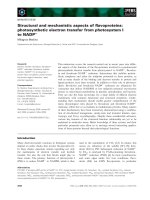


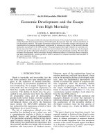


.push({});</script> </div> </div> </div> <div class="vf_link_relate px-2 my-2"> <h2 class="vf_doc_relate text-2xl font-bold my-4">Tài liệu liên quan</h2> <ul class="grid grid-cols-12 gap-2"> <li class="col-span-6 md:col-span-2"> <div class="card-doc " onclick="actionDocRelated(this)"> <a class="card-doc-img" href="https://text.123docz.net/document/74850-bao-cao-y-hoc-high-intensity-non-invasive-positive-pressure-ventilation-for-stable-hypercapnic-copd.htm" title=" Báo cáo y học: " High-intensity non-invasive positive pressure ventilation for stable hypercapnic COPD"> <i class="icon i_type_doc i_type_doc2"></i> <img class="lazy" src="data:image/gif;base64,R0lGODlhAQABAIAAAP///wAAACH5BAEAAAAALAAAAAABAAEAAAICRAEAOw==" data-src="https://media.store123doc.com/images/default/doc_normal.png" width="124" height="179" alt=" Báo cáo y học: " High-intensity non-invasive positive pressure ventilation for stable hypercapnic COPD" onerror="this.src=)